
3
Smart Corrosion Management Elements
Reza Javaherdashti1 and Faranak Javaherdashti2
1 Eninco Engineering B.V., Hengelo, The Netherlands
2 IMI (Industrail Management Institute), Tehran, Iran
3.1 Introduction
Management of corrosion differs from corrosion management (CM) in that it has a strong management component attached to it. Based on all definitions given so far for CM, it can be inferred that CM deals with the risk of corrosion and this is, at its best, just half of the truth about management of corrosion.
In this chapter, we want to look at a concept that so far has been known as CM from a different angle. We would like to address confusion that we have observed in our contacts with industries; and that is mixing up CM with corrosion engineering with a sugar coating of some cost analysis. Even in CM‐related papers and documents published by reputable corrosion authorities, approaches toward CM seem to have been a mix of diagrams, procedures, and step‐by‐step documentation procedures that do not address anything but a technical issue related to corrosion; premature failure of a part in a system, coating disbondment, or concrete spalling.
However, as the very name implies, CM is composed of two parts: corrosion, which is a technical issue; and management, which is related to what humans do. In other words, any CM approach would have to include engineering/science of corrosion in addition to the human factor related to design and application of strategies, procedures, policies, and rules put forward by the management team or the manager.
To overcome this gap of understanding that exists about CM even among professionals, we have introduced a new concept that we call Corrosion Knowledge Management, or briefly CKM. In this chapter, we will concentrate on both CKM and CM. The reason is that CM and CKM are not opposite to each other, but they must be regarded as completing each other.
In the following sections, we will also put emphasis on the concepts of Risk and Importance; these two terms are in fact the most significant sources of managers taking corrosion lightly. The reason, as we will discuss, is that risk of corrosion is not the same as its importance and vice versa.
We will order the topics to be discussed in this chapter by first touching the sensitive issue of risk and its vast difference from importance. We will then continue with CM and CKM.
3.1.1 Risk, Importance, and How They Are Interrelated?
Risk has different perceptions, although one can find meaning for it. Perception of risk is important to be defined clearly and within a certain frame so that it will be communicable to others, meaning that it will be possible to transfer to others the importance and gravity of the incoming danger. In everyday life, risk is usually associated with anything from working with kitchen shears to driving; there is always the risk of cutting your hand or hitting a car. It is in this context that risk and its significance must be of an essence that can be realized by others. Driving is an activity in which if the real value of risk of hitting each other is understood and appreciated by all drivers, so the risk of driving becomes controllable and manageable. The importance of risk from an engineering point of view is another story. That is because risk in engineering terms is much clearer and more attainable than the usual meaning of it in day‐to‐day activities.
For a corrosion engineer, risk of corrosion can be interpreted as how close the system of interest is to failure should corrosion be the only prevailed mechanism. In other words, the engineer measures the risk in terms of corrosion rate and the part's thickness. If, for instance, the thickness of a metallic part is 1 mm and the measured corrosion is 0.1 mm per year, it means that maximum 10 years can be taken as the safe margin of service life for that part (due to practical reasons, it is better, however, take that service life span as 8 or 9 years instead of 10). Figure 3.1 shows the categories by which corrosion severity can be addressed based on corrosion rates, as per NACE standard RP0775‐2005.
However, risk has a much wider meaning. Risk is a function of likelihood of an event (hazard) and the consequences following it. In other words, if there is a small likelihood of a hazard occurring, but it does occur, then it will have rather serious consequences, its risk is high no matter what the likelihood could be.
Risk has a known definition: it is the by‐product of likelihood of an event (here, corrosion) by its consequences. It is based on the level of risk thus defined that acceptable corrosion risk can be assessed. However, there are many uncertainties here; how, for example, we define consequences? In terms of the money to be lost or in terms of environmental impacts? If it is the former, is it the present value of the asset that concerns us, or its relative value with regards to where the asset fits in a chain of demands and purchases? In case of the latter, how it is measured? Or rather, how it can be proposed to be measured? Is there a systematic approach to estimate the indirect cost of corrosion? How can ecological impacts of corrosion be prevented, controlled, or assessed? What is the difference between 'corrosion control' and 'corrosion prevention'? Above all, how do we define importance in engineering terms? If we define engineering importance as a function of both risk and cost, meaning that if somethings risk and cost are high it is then important, how, then, can we connect engineering importance with CM?

Figure 3.1 Categorizing corrosion severity based on corrosion rates (general and localized corrosion).
Source: Mr. Ricardo Gonzalez.
First things first, how do we define consequences? API 580 part 4.1.5 defines consequence as An outcome from an event. There may be one or more consequences from an event. Consequences may range from positive to negative. However, consequences are always negative for safety aspects. Consequences may be expressed qualitatively or quantitatively [1].
Consequence could be interpreted as damage to the capital or environment – or both. The leakage of BP‐owned pipeline (Prudhoe Bay Field event in 2006) was an example of a corrosion event whose consequences were financial as well as environmental.
In calculating the risk, one important factor is to know or at least estimate the consequences that could occur. The likelihood (probability) of the event is also of paramount significance.
Let us think about risk and the factors involved in it in a more detailed, somewhat mathematical way. There are four factors involved in calculating risk (R):
- Life factor, shown with L. It is the number associated with the remaining useful life of a part/component of a system.
- Consequence Factor, shown with C. It is quantitative assessment of consequences that can occur should corrosion becomes an event being worth notice, or being worth being branded as a serious cause. Some of the consequences resulting from a corrosion event are:
- Safety: it is possible that as a result of corrosion, safety become a serious matter of concern. The explosion of the natural gas pipeline Near Carlsbad, New Mexico on August 19, 2000 in which a young family dwelling nearby perished. There are both documented and witnessed cases where corrosion was the main culprit in sacrificing the safety of workplace [2].
- Production: corrosion can interrupt with the scheduled, normal regime of production. In 2010, mainly due to negligence of corrosion in a Petrochemical complex in Iran (Pardis Petrochemical Complex [3]), there was a disastrous fire that, reportedly, postponed production for nearly two months.
- Repair: the scheduled repair (overhaul) that is preferred to emergency repair (shut down). To show the adverse effect of unplanned shutdowns one can note that Indonesia experienced a reduction in its crude oil sales during the first half of the year 2014, that in part, was the result of 122 unplanned shutdowns from the operator BPMigas, which created 6860 bpd in lost production [4].
- Operability: meaning that when a part is corroded, it is not always easy to operate the equipment as easily as it used to be. An example of this condition can be seen in Figure 3.2.
- Environment: one of us (R. Javaherdashti) has written a book about a decade ago regarding environmental impacts of corrosion [5]. Some environmental disasters and catastrophes related to corrosion have also been reviewed elsewhere [6, 7].
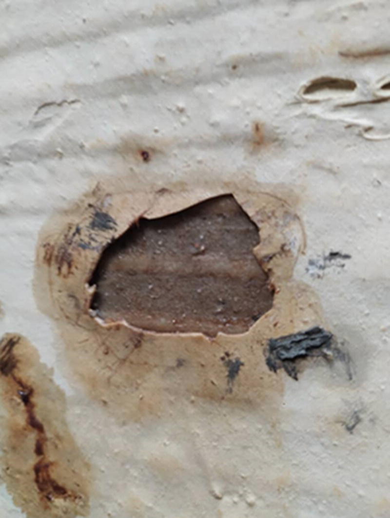
Figure 3.2 Damage of the inner layer of a protective coating applied inside an acid tank (biologically produced sulfuric acid) after being in service for about one year. The underlying substrate is the carbon steel body of the tank. A typical tank as such had a localized corrosion leading into severe leakage.
(Source: Image courtesy of Dr. Reza Javaherdashti.)
- Third party interests: if corrosion happens on one's asset, its impact may not be limited to the asset owner only. As reported in ASM (American Society of Metals): "the sudden collapse because of corrosion fatigue of the Silver Bridge over the Ohio River at Point Pleasant, OH in 1967 resulted in the loss of 46 lives and cost millions of dollars" [8]. This and similar examples can clearly show how corrosion can affect several factors.
- Customer and public perception: just imagine a car you purchased has a rusting exhaust or chassis. Defects as such, which are often not noticed by regular customers, are considered great losses in the life cycle of the car for anyone who buys that car. Factors affecting customer perception are typically "advertising, reviews, public relations, social media, personal experiences" [9]. In fact, it appears that corrosion scientists and engineers have taken this aspect very seriously, for example, for cases in which corrosion may lead to disasters such as water poisoning [10].
We have reviewed aspects of corrosion that are reflected onto our lives elsewhere [11].
Table 3.1 Consequence rating (F) of some consequence ratings.
Consequence Rating (F) 1. Safety (to personnel and/or public) 10 2. Loss/delay of production 10 3. Environmental pollution 10 4. Loss of quality of the product 9 5. Loss of customer confidence 7 6. Interval between repairs 8
- Consequence rating, F, is an arbitrarily selected ranking to designate what consequence is – relative to other consequences – of greater importance. On a range of 1 (the least important) to 10 (the most important) consequences, it is possible to arrange a ranking factor, or equivalently, a consequence rating as in Table 3.1, below:
While the figures given for F in Table 3.1 are chosen on an arbitrary basis (and obviously, open to discussion), the importance given to them is not that arbitrary. In fact, comparing the first three items show that for the operator/owner of the business, these three consequences are equally important, yet item 5 is of lesser significance. It is possible that based on the understanding of the business owner/operator, other F values are assigned, however, the relative values between the F values is of importance.
- What is important is what to be considered as an event which is worth of being considered for its consequences. This will bring another rating factor that is called an Event Rating, designated by P. For example, within the safety category of consequences, can a pinhole in a line carrying toxic material be considered a serous event with serious consequences, what about a crack in the same line? Is a crack in a toxic fluid line a serious event, what about a crack in a line carrying flammable fluid? Within the category of pollution, is it the pollution induced in soil of more importance or in water? If we are talking about events in an offshore oil and gas platform, it is certainly the seawater pollution that deserves to be considered as an event to which an arbitrary value for P is assigned. For a solar panel farm, it is the atmospheric pollution that matters, and so on. Here, again, a ranking system can be constructed assigning a 1 (least important) to 10 (most important) value for the event factor. As with consequence factor, it is not the absolute values assumed for items that matter, but the relationship between them and how these relative figures can be interpreted with regards to each other.
Based on the above risk (R) can be taken as a function of life factor (L) and consequence factor (C). C itself is a function of F and P, and it will be the summation of each C factor (and related F and P factors) as mathematically shown below:

The above equation relates the consequence factor with the ratings (F and P). It will enable us to construct a matrix that consists of probability (of corrosion) with related consequences, yielding risk categories, an example of which is given below, in Figure 3.3:
Obviously, it is necessary to avoid risk from zone 1 (high consequence and high probability) to zone 4 (low consequence and low probability). Figure 3.4 shows an example of equipment that more or less fits zone 1 conditions.
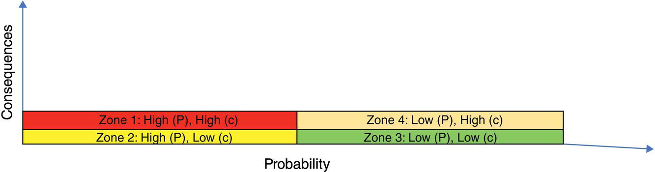
Figure 3.3 Risk categories and four zones created based on level of consequence and probability.
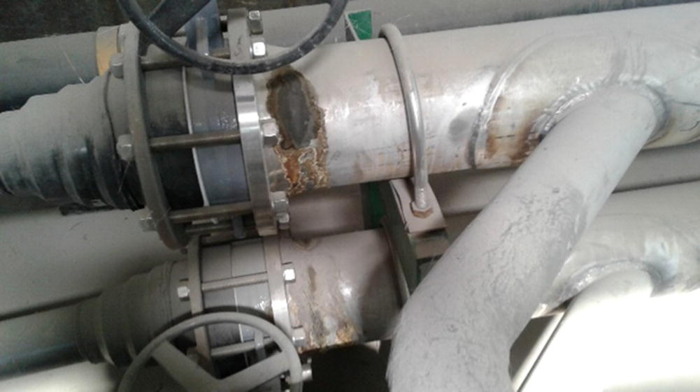
Figure 3.4 An example of CUI (corrosion under insulation) on a piping which is an essential part of a water treatment facility. Due to CUI, the (corrosion) probability is high and the equipment failure (consequence) is also high.
(Source: Courtesy of Dr. Reza Javaherdashti.)

Figure 3.5 Irritation situation zones, where P (probability) and C (consequence) could yield various situations. Two examples for these zones are also given.
While zones 1 and 4 are serious and safe alerts, respectively, it is zones 2 and 3 that can be called irritation situations. Examples of these zones are given in Figure 3.5:
It is necessary for us to focus more on the meanings that can come to mind; when in Zone 2 we talk about high probability, and low probability in zone 4. However, before that we must answer a question whose answer may seem too obvious; how can probability about something be linked with the knowledge about it? In other words, why we call a case like that shown in zone 2 a high probability and a case like zone 4 a low probability case?
In fact, the more data we have about something (that is to occur), the more we will be able to assess if it is really going to occur with high or low probability. As an example, if we have data (prior knowledge) that a flammable material is placed near flame, then it is sensible to reason that the probability of fire is high. It follows with this assessment about probability that it is then possible to separate the flammable material from the flame, and therefore lower the consequences.
It can also follow, then, that risk is a very delicate issue often mixed up with likelihood by many, including professionals; likelihood shows the possibility of a hazard – here, corrosion – whereas risk measures the aftermath of the likelihood in terms of both the likelihood and the consequences that can occur after corrosion has taken place. Industries, not all of them of course, think that because they have taken all measures against corrosion, then they are safe. However, from experience, the bitter fact is that not all forms of corrosion may not be known. There are at least two reasons for that:
- Different corrosion mechanisms as observed in different assets: basic assets in any plant consist of (i) utility, (ii) process, (iii) fire water ring/system, (iv) fuel lines, (v) feed lines, (vi) product lines, and (vii) waste lines [12]. Each of these assets has various types of corrosion processes already taking place in them that could be vastly different from each other. As an example, the corrosion problems in boiler, turbine, and hotbox‐condenser in a power plant are different from each other. Also, problems associated with the waste material could be of another nature compared with corrosion problems in hot spots of the plant (for example, within waterwall tubes).
- Different corrosion geometries [13]: even within one asset there can exist several corrosion mechanisms that are in competition with each other. These corrosion processes can be in series or parallel geometries with regards to each other, meaning that they can either enhance one another or occur independently from each other. This is a particularly important aspect of any problem‐solving scheme. Figure 3.6 shows an example in which series and parallel corrosion reactions geometries can be observed. In the duct, examples of parallel reactions are (i) the damaging effect of atmospheric corrosion on the external coating, and (ii) internal corrosion of the fluid inside the pipe. This means that these corrosion reactions can take place independently from each other. However, when it comes to series corrosion reactions geometry, a likely corrosion scenario could be the detrimental, gradual corrosion of welds by the corrosive fluid inside the side‐pipes.
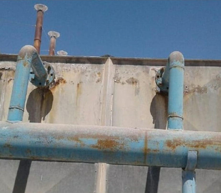
Figure 3.6 An example of corrosion reactions geometries.
(Source: Photo: Dr. R. Javaherdashti's collection.)
Therefore, risk of corrosion is an important issue that must never be confused with the likelihood of corrosion, and being conscience about this difference must also be reflected in any CM scheme.
3.1.2 Corrosion Management: What It Is and What It Is Not
In both rather famous definitions of CM given in 2001 [14] and 2016 [15] by authorities,1 CM is related to the management of risk of corrosion. In the 2001 definition of CM, there are two especially important concepts; risk of corrosion and corrosion control. In 2016, however, the pivotal concept of the definition is to manage the threat of corrosion. In a previous publication [12], we have differentiated the importance discrepancy between corrosion prevention and corrosion control and will not repeat it here. However, the most important aspect of CM, as both definitions also imply, is the risk of corrosion. The importance of highlighting risk is due to the role it plays in defining Engineering Importance.
Engineering importance is a function of both risk and cost. This means that from an engineering point of view, if somethings risk and cost are high, then its importance is high and must be regarded as something important. From the definitions given for CM it follows that CM is mainly concerned with the risk of corrosion. In other words, CM looks at those factors that are likely to create the risk of corrosion.
Being as such, CM will look at all the factors that will make a system vulnerable to corrosion. A part of these factors will be corrosion engineering/science, but what is not there is corrosion cost considerations. In other words, corrosion scientists and corrosion engineers try hard to control conditions that will lead to creating the risk of corrosion. It is in this regard that we believe corrosion professionals often use CM as a new way to look at their old problems; a recent example of such is the Bechtel CM model, presented at NACE in 2016 [16]. This model, as reported [17], is composed of some steps that are very briefly explained in the following:
- list of all probable corrosion scenarios;
- evaluation of each threat;
- feasibility of using various remedies (such as using low‐cost construction materials or corrosion‐resistant alloys [CRA]), or non‐metallic materials based on a life cycle cost (LCC) analysis;
- determination of corrosion control (CC) technology;
- selection of proper monitoring and inspection technique(s) to determine how well the remedies suggested and applied in step (3) work;
- receiving feedback on the reporting and analysis of suggested monitoring and inspection methods in order to apply corrective measures, if necessary. This step would also work as a medium of interaction between corrosion the engineering team, operations team, and the facility owner.
In the same way that there is a Bechtel CM model, there are other CM models that are often referred to by the names of the companies in which these models have been developed and applied, such as BP model, Petronas model, Total CM model, etc.
Bechtel CM model is one of the most recent CM models developed in a reputable company, however there are points associated with this model that are more or less also true with other CM models. For instance, Bechtel model is too technical and rather an engineering model, meaning that it is only understandable and applicable by an engineer and not by, say, a financial manager at a company. Apart from the section that deals very briefly with economy in terms of LCC, this model has no room for a cost analysis in terms of what would happen without this model. In other words, Bechtel looks at the economy of using anti‐corrosion measures from materials selection to selection of inspecting methods (visual, radiography, eddy current), but it assumes that anyone who is to use the model already knows how much damage it causes. This assumption is not necessarily true for all companies, whether in the oil and gas sector or elsewhere. We believe that any CM model must also be accompanied by yet another model that is specified for the cost of corrosion only. The Bechtel model lacks this economy and management side.
Each CM model must also come up with a management model that would mainly serve the higher management (the one with 'might and right'). Real life experience shows that while a CM model may be good for one company, another company may not want to use it or may want to have another model that is essentially the same as other models, but with a different manifestation.
Item (1) of this model is silent on corrosion geometry, in other words, it is not accompanied by a nomenclature that would define the following:
- Based on the conditions, definition of corrosion scenarios may change. Note that there is a difference between knowing a corrosion process and knowing how it can be effective in an overall corrosion scheme. For example, one may be a very informative, skilled professional about microbial corrosion, microbiologically influenced corrosion (MIC), and in the corrosion system (that is, a system whose corrosion is important for us), MIC does exist. The point is how MIC will become the main operative corrosion process when compared with other competing corrosion processes. This is what we call corrosion reactions geometry.
- Failure in engineering terms is when a material is not functional any longer. In other words, a failed material/component is no longer being considered for the job it is supposed to do. However, failure has a much wider meaning that must be taken with some delicacy. In fact, before the material fully fails, its failure could have already started. This is a very important point often missed by CM model developers. They assume that their main tasks are definition of corrosion threats, then how to remedy and monitor it so that it will not recur. While this is certainly an especially important core of any CM model, it should not be taken as the main point; the main point in any CM model is not prevention of failure, but prevention of conditions that would lead to failure.
In fact, the main deficiency of all existing CM models is that they have no preparations for the persons who may have little or no corrosion knowledge, in addition to clear definitions of corrosion scenarios and failure. When we talk about our own approach toward CM, we will discuss the above with more details.
On the other hand, there is an incorrect perception even among professionals that CM just belongs to oil and gas industries. These authors believe the main source of this mistake is that corrosion specialists working in oil and gas have been much more active in constructing CM models compared with their counterparts in other industries. It seems that because of the prevailing nature of oil and gas industries and higher activities of corrosion professionals in this field, CM models are remembered with the names of famous oil and gas companies (BP, Petronas, Total, Bechtel).
In the next section, we will talk about our approach toward corrosion that we call Management of Corrosion.
3.1.3 Management of Corrosion
Management of corrosion is not just a simple play with words, it is an umbrella below which the following six concepts must be considered. These concepts are:
- Geometry of corrosion processes;
- Definition of failure within a new context;
- Corrosion prevention (CP) and CC;
- Javaherdashti CM model;
- Corrosion cost estimation model;
- CKM.
Based on our 20+ years of experience in various industries around the globe, that stretches from Papua New Guinea and Australia to the UK and the Middle East and South Asia, and being involved with CM in oil, gas, and petrochemical industries, along with automotive and mining, we strongly recommend that any approach toward management of corrosion must be taken as a package containing the four items we previously mentioned. We have talked about these four items in our numerous publications before, but it is the first time that all four are taken together as a package to address management of corrosion properly. Although we have explained some of the above in here and in other resources, it is worth of repeating them all here.
3.1.3.1 Corrosion Reactions Geometry
Corrosion reactions happen in one anodic reaction (losing an electron) and – based on several factors such as, but not limited to, oxygen availability, pH, electrochemical stability of chemicals in the environment, temperature, and the like – several cathodic reactions (gaining electrons) that if one is not happening, the other one can replace it. Therefore, right from the beginning, the electrochemistry of corrosion is based on not one but more than one reaction.
In addition to that, real‐life working conditions are far different from controlled, design conditions of corrosion laboratories; under laboratory conditions corrosion reactions are mimicked, accelerated, or reconstructed. These three features which are essential to laboratory experiments, do show the deep gap between experimental and industrially experienced findings.
Under working circumstances, mostly several corrosion reactions are operative. Some examples could be:
- Hydrotested pipelines; in these systems there are at least four corrosion processes that, based on the chemistry and microbiological as well as electrochemical conditions, could exist [18], the most important of which being microbiologically influenced corrosion (MIC). In a system as such, it is very important to know if the involved governing corrosion processes are acting in series or in parallel geometry to each other: if the MIC problem can initiate or launch galvanic corrosion between the weld and the parent material of the pipe, then by solving either end of the problem (treating MIC or resolving the existing corrosion potential between the weld and the parent material), the corrosion problem can be solved.
- Bioleaching tanks; in these tanks the normal process for tank bioleaching is that bacterial culture containing Sulfur oxidizing bacteria (SOB) will dissolve certain mineral (for example copper) concentrates to yield an industrially pure metallic form of the required element. Due to the very nature of the reactions in the tank, both erosion (as induced by concentrate lumps accelerating by the action of a mixer) and MIC, as induced by the action of the bacteria, can exist. It is then a matter of the electrochemistry, as well as the hydrodynamic of the concentrates inside the tank, that being in series or parallel geometry is determined.
Having a series or parallel corrosion reactions geometry has a very important impact on the way an overall corrosion problem is being treated; consulting efforts for a series corrosion geometry could be much easier and even more cost‐effective than a parallel geometry, by picking up the main corrosion process and treating it, it is highly likely that the overall corrosion problem will be resolved. In case of a parallel geometry, however, such chances are very slim, as it is highly likely that the involved corrosion reactions are acting independently from each other so that by solving one, the others will not be resolved. In addition, it is also possible that one branch of an overall parallel corrosion geometry will itself consist of a series of parallel and series geometries, thus making the overall picture even more complicated. Figure 3.7 shows an example of such a complex system in which external corrosion of a buried pipeline has been illustrated. In this respect, overall corrosion geometry is in parallel geometry consisting of three rows. Each row consists of corrosion geometries which are in series form.
For instance, the first row discusses soil properties from soil particle size (I) to its microbiology (II), and its pH, moisture, and conductivity (III). Likewise, the other rows will be related to other components of the whole corrosion scheme.
The complexity observed in the two examples given above can also be seen in other equipment and assets. As can also be seen, it is not that easy to talk about all possible corrosion scenarios if the geometry of such reactions with regard to each other is not known. A skillful corrosion engineer may realize what the corrosion processes are in each asset, but it is equally important to realize how these corrosion processes are prevailing in the overall corrosion scheme in the first place.
3.1.3.2 Failure
Failure is normally regarded as a phenomenon where the extent of physical damage is so large that the equipment cannot be used any longer. Failure seems to have been understood as a self‐evident issue so that by merely speaking about it, everyone would know what the topic is, but the fact is that it is not that straight forward to define failure.
In order to define failure, we must remind ourselves again about a principle that we mentioned earlier; our philosophy must not be treatment of failure but finding ways to avoid allowing failure to occur. In other words, our mission must be to prevent ways by which failure is highly likely to happen, not the failure per se. In this regard, our job will be more or less like crisis management; crisis by definition has no management as it is unmanageable. It is in fact pre‐ and post‐crisis conditions that can be managed. Pre‐crisis conditions must be managed effectively not to give way to crisis, and post‐crisis conditions must be managed to minimize the impact of crisis.
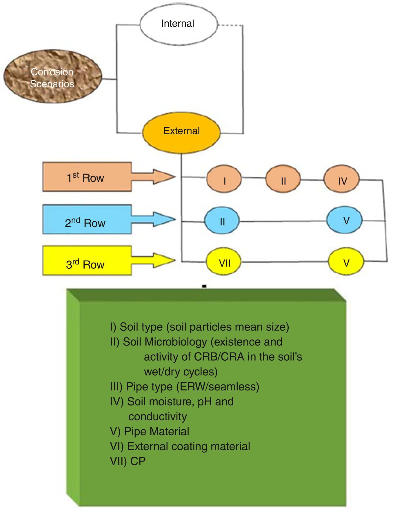
Figure 3.7 An example of a rather complex corrosion geometry related to external corrosion of a buried pipeline; overall corrosion geometry is in parallel form (geometry) where each branch itself consists of some series corrosion geometries.
(Source: Figure taken from Javaherdashti and Akvan [12].)
The thermodynamics of corrosion was emphasized to show that it is indeed a naturally occurring process. This means that corrosion cannot be stopped (the next section will discuss CP and CC and what the differences are between them). It can alternatively be said that corrosion is something that one has to accept, as long as pitting that would occur as a result of non‐uniform, localized corrosion is not leading to leakage. Prior to that, we want uniform corrosion (that is easier to handle in both prediction of its effects and controlling them) not to be replaced by non‐uniform, localized corrosion, an important result of which is pitting. While there have been many attempts to find an algorithm/pattern to predict pitting (even by using scholastic approaches), the unpredictable nature of pitting has always remained like a Damocles sword upon the head of corrosion technologists and engineers. Therefore, what is desired for us as operators or maintenance specialists with regards to CM can be summarized as in Figure 3.8 as an example of what we can call a 'corrosion safety procedure' for an asset such as a pipeline:
Taking the metaphor of a train reaching its last station, as far as corrosion safety procedure is concerned, leakage is the last station for the safety train. After the last stop, seen here as 'leakage' from the pipe, failure is inevitable. Therefore, failure in its classic meaning is where the mechanical integrity of the asset is lost and something like leakage from a pipe occurs. In pure engineering terms, failure is where the asset becomes useless.
The lack of usefulness and loss of mechanical integrity and strength has been introduced into corrosion engineers' books and nomenclature from a mechanical engineering understanding of materials.
For us, the stages through which failure is facilitated are important. In fact, it is only through these stages that a corrosion engineer can have the chance of controlling corrosion (in the next section we will explain the vast differences between CC and CP). To explain these stages, we need to become familiar with three definitions that we will be using through this chapter:

Figure 3.8 Corrosion safety procedure. The way corrosion must not proceed in order to make any damage; corrosion must not become non‐uniform in its morphology (localized corrosion) to yield pitting. Even if pitting happens, leakage must not occur.
- Fit‐For‐Service State (FFS): When an asset/equipment passes all the necessary tests as required by standards and professional approval of an inspector, it is said that the asset is ready to be put into service and it is fit for the intended service. In this state, it can safely be assumed that the asset is corrosion‐free, or at least the extent/severity of corrosion is not significant enough to prevent the asset from being labeled as FFS.
- Pseudo‐FFS State: As soon as the equipment is put into service, it will face conditions that will affect its corrosion resistance. In other words, the asset will experience corrosion immediately after being put into service. When the asset undergoes this status, it is still being used by the operator of the plant or asset manager simply because the measured corrosion rates are still within acceptable range or the corrosion is still within the limits of being controllable. This state is not the same as FFS state but is similar to it, thus the name pseudo‐FFS.
- Zugzwang State: Zugzwang is a term in chess, simply meaning that whatever move one does, one will lose. No matter what your position is in the game, the game is doomed. In this context, we define Zugzwang state as per the below two definitions, and based on whichever would fit the situation of the asset, we may call it a Zugzwang effect status, Figure 3.9.
Figure 3.10 shows two examples of pseudo‐FFS and Zugzwang effect state.
Figure 3.9 Two alternative definitions of Zugzwang effect state. Based on the severity of the case and repeatability of repair costs, alternative definitions can apply.
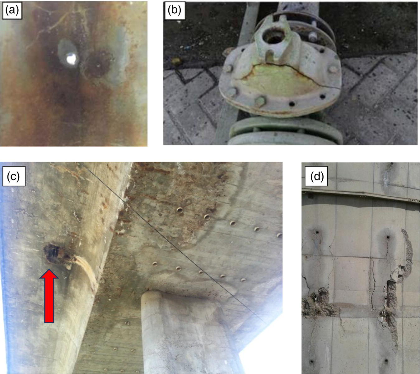
Figure 3.10 (a) A through‐wall hole (at 6 o'clock position) of a stainless steel 316 pipe in which seawater remained stagnant for four months. (b) A cracked connection still used in a petrochemical complex. (c) Failure of reinforced concrete surface below a concrete highway bridge. (d) Spalling on the concrete wall of a cooling tower that looks toward sea.
(Source: from Dr. Reza Javaherdashti collection [12].)
In Figure 3.10, figure A shows an example of an asset in its Zugzwang effect state, whereas figure B shows an asset in its pseudo‐FFS state. In figure (A), the pipe is out of service completely due to the existence of the through‐wall hole. However, in figure (B) the asset is still in use merely because its condition is not critical enough to push it out of service. In fact, a great number of assets already in use in all industries are in their pseudo‐FFS status.
Based on the above, then, failure will be put into a new context which is simply this: Failure is when an asset reaches its Zugzwang effect state. Alternatively, the job of a corrosion consultant/engineer must be two‐fold; increasing the time between FFS and pseudo‐FFS states as well as the time between pseudo‐FFS and Zugzwang effect states. The relationship between these status conditions through which the asset will travel is schematically shown in Figure 3.11.
As components in Figure 3.11 show, as the asset moves from FFS toward pseudo‐FFS, and from pseudo‐FFS to Zugzwang effect status, there is a need for both inspection and maintenance. As implied earlier, the shorter the distance between pseudo‐FFS and Zugzwang effect status points, the more likely that failure will happen. The farther the distance between FFS and pseudo‐FFS, the safer the asset is to operate. This is also applicable should the distance between pseudo‐FFS and Zugzwang effect state be as far as possible, because that would mean that the equipment is in such good shape that failure is not likely to happen within a short time.
Therefore, by using the above concepts it is now possible to define what any useful CM must aim for. This can be stated as below diagram, Figure 3.12.

Figure 3.11 The relationship that exists between FFS, pseudo‐FFS, and Zugzwang effect states by which the role and position of inspection and maintenance activities are also related.

Figure 3.12 Milestones in the life of an asset from its fresh state of FFS to its failure.
As Figure 3.12 shows, there are milestones that can be assigned to the service life of an asset from the time it passes all the required inspection and fit‐for service standards and codes, to the time it arrives at its Zugzwang effect state and it has failed. This pathway will also involve both inspectors and corrosion engineers/consultants, as well as integrity management technologists.
While the figure is self‐descriptive, particularly regarding what was mentioned above, it is worth noticing that the expertise involved and highlighted in Figure 3.12 are not all that is required. In other words, there is certainly a blend of experts and expertise needed to gain a correct evaluation and assessment. This is particularly true when Figure 3.12 is looked at within the context of Figure 3.11. As it appears from Figure 3.11, inspection and maintenance experts are to accompany the CM consultant at all times. It is also obvious that to keep the asset at its FFS state for as long as possible, technical feedback from inspectors is vital; it is based on what they see and report that the CM engineer can decide how critical the situation is and how it must be handled.
It is also a very important to understand that any CM approach is a collective work and it flows from bottom to top, and not the other way. What is meant here is that top management will be provided the feedback from the CM team, and if the decision taken by the top management proves to be incorrect down the line, it is highly possible that the CM team have not communicated effectively enough with management. We have seen an example of such poor communication between the engineering team and the financial management so that just based on pure accounting (not economical) considerations, refusal to use a better inhibitor instead of a less effective but less expensive corrosion inhibitor cost the plant dearly [5].
No CM scheme would be complete without discussing the important difference between CP and CC. This is a concept that, even by corrosion professionals, is often neglected and used without paying attention within a CM scheme; if the differences between these two terminologies are not taken into consideration, several confusions may be created. We will explain these terms in the next section.
3.1.3.3 Corrosion Prevention and Corrosion Control
Thermodynamics of corrosion teaches us that corrosion cannot be stopped, nor can it be prevented. However, CP and CC are terms that are being used interchangeably even in many official documents related to CM; as reported by NACE [15], one of the objectives mentioned in the long‐term corrosion strategy plan submitted by the US Department of Defense to the Congress in 2003, reads verbatim "Formation of a multi‐service corrosion prevention and control … team."
The fact, however, is that CP and CC are not the same at all. CP and CC differ from each other in features that can be summarized as in Table 3.2:
When we are in CP mode, based on the nomenclature we developed in the previous section, all efforts must be done to stay at FFS without letting the asset to move toward the pseudo‐FFS state. When on CC, all efforts must be performed so as not to arrive at Zugzwang effect state. This is a very important matter, as by knowing where the asset is the required strategy will be prepared, and for that reason it will be possible to prepare the required strategy.
Table 3.2 Some important features of corrosion control (CC) and corrosion prevention (CP).
| Corrosion control (CC) | Corrosion prevention (CP) |
|---|---|
| The equipment is in use (Brownfield projects). | The equipment is not in use or not extensively used (Greenfield project). |
| Corrosion Management is in the form of controlling corrosion and keeping it at less than 5 mpy, as per NACE corrosion rate requirements. | Using correct design and application parameters, corrosion can be kept at very low values so that no damage will be experienced. |
| OPEX (Operation Expenses) are high. | CAPEX (Capital Expenses) will be high but OPEX (Operation Expenses) will be low. |
Distinguishing CP as described in Table 3.2 also reveals and explains the seemingly contradicting issues between thermodynamics of corrosion (that defies prevention of corrosion) and the way corrosion technologists normally refer to CP. As it appears, even when we are in CC mode, corrosion is not being prevented but it is kept within restrains to keep it manageable enough. On the other hand, CP in this context can only be mentioned if right from the beginning all possible conditions leading to corrosion are seen and addressed.
An example of CP could be by changing the design. An example for a design change that would eliminate the corrosion problem (appearing in the form of corrosion under deposition due to the establishment of differential aeration cells) is to solve a galvanic corrosion problem of a carbon steel pipe with a small total area, with respect to a stainless steel pipe with a larger area (small cathode versus a large cathode that will be leading into sever corrosion), by either using the same material as the stainless steel pipe or using stainless steel as the anode and the carbon steel pipe as the cathode (small cathode versus large anode). Yet another example could be putting a valve under a suitable place in a basin so that by discharging the fluid, no stagnant conditions for the fluid inside the basin will be created, leading to possible corrosion mechanisms under the deposit (such as but not limited to, MIC).
From another point of view, CC is dealing with 'as is' whereas CP is dealing with 'to be' conditions of the asset. As is, as the name implies, shows the present condition of the asset. In other words, it shows how tolerable corrosion conditions are when the asset is considered from a CM point of view. Taking CP as an ideal state of engineering CM measures, to be shows the ultimate solution or conditions that can be expected. It follows that if the current (as is) condition of flow rate in a pipeline is, for example, less than 1.5 m/s so that stagnant conditions are encouraged leading possibly into the likelihood for MIC to develop, the target (to be) must be increasing the flow rate to disturb conditions for biofilm formation.2 When the flow rate is below the limit mentioned, the conditions will need to be controlled (CC), and when we increase the flow rate so that biofilm formation is prevented (2), it is then as if biofilm formation as a prerequisite for MIC has been prevented (CP).
3.1.3.4 CM Model
The corrosion model we are presenting here rests on more than two decades of personal experience in CM and troubleshooting in various industries around the globe. In the above sentence we have emphasized upon there important elements that serve to qualify us for presenting a model:
- Field as well as academic experience; CM models must not be developed based on either pure field or academic skills and must actually look into combining the two within a suitable context. While the framework and context of such a blend must rely on theoretical basis, the application must be sensible enough when applied,
- Different industries; so far all the CM models we have observed and to the best of our knowledge, have been proposed to deal with oil and gas industry, perhaps with the exception of one model suggested to deal with CM issues in mining industry in Western Australia [19]. The fact is that corrosion is not just an issue in oil and gas industry, but in all industries ranging from mining to power generation and others, therefore, the more diverse industries one has knowledge of, the better the engineering understanding of the systems and processes. In addition, in some industries it is the process‐associated corrosion problems that are of interest. In fact, corrosion problems in any industry can be divided into three categories; (1) corrosion problems associated with the main process, (2) corrosion problems associated with auxiliary systems, and (3) corrosion problems associated with safety systems and equipment. In a power plant, for instance, category 1 problems are associated with corrosion problems for boiler, turbine, and condenser; whereas category 2 problems are those related to cooling tower, soot blowers, or boiler feed pump; and category 3 corrosion problems are mainly associated with underground metallic firewater rings. In a petrochemical plant, for example, category 1 and category 2 corrosion problems are of significance and most of the time category 3 problems are not taken seriously unless there has been a history related to it. Working as a corrosion consultant for a wide range of industries gives one the opportunity of getting familiar with the work culture of each, and therefore allows a much broader horizon for engineering disciplines than having worked in just one business in a given industry,
- Having a rather global culture about corrosion is a vital feature of any CM model that is to be proposed on an international level; the main defect of models proposed by mostly Western‐minded professionals is that they look at CM through their own window. For an industry that exists in a country where the currency rate between internationally accepted monetary units such as dollars or euro versus its national monetary system is not stable, it is quite unrealistic to propose expensive means of corrosion monitoring, inspection, and treatment. In a culture where there is no previous history about cost of corrosion or even a record about parameters required to define a corrosion cost model (to be discussed in the next section), not giving an algorithm on how to obtain such data, any CM model is to be doomed with incompetency when faced with realities.
While the Javaherdashti CM model takes the essential elements of CM that, like any other CM model is more or less similar for all CM models, its successful application is only possible if all the six elements for a system of management of corrosion are also ready and applicable.
The Javaherdashti CM model has four phases and six steps, as we will now discuss.
3.1.4 Phase 1: Definition
In this phase the following steps are defined:
- Define the corrosion system. Contrary to how it may seem, the meaning of a corrosion system is not too evident. In simple terms, a corrosion system is a part of a system that, due to a corrosion‐related reason, is of interest to us. Therefore, if we are looking at corrosion problems related to the waterwalls in a boiler in a power plant, then the corrosion system is those waterwalls, but not other parts of the boiler. Another example is investigating MIC or CUI in a certain part of a given asset. Considering corrosion systems can be divided into two categories: CINS (corrosion in the system) and COFS (corrosion of the system). In a CINS approach, all possible corrosion scenarios for all parts of a given system are investigated, whereas in a CINS just a limited number of both the equipment and subsystems are of interest. More details have been given elsewhere [12].
- Define the corrosion problem(s) and their geometry. This is a matter for which a strong scientific background is necessary. Obviously, to realize the corrosion reactions involved, a good knowledge of theoretical basis is required, not to address atmospheric corrosion, CUI, and MIC incorrectly, but because all of them are electrochemical in nature. As we mentioned earlier, in many real‐life corrosion systems (hydrotested pipe, bioleaching tank, and the like) there is more than one corrosion reaction involved, so that there is always a competition between these reactions. It is equally important to know the geometry of corrosion reactions to determine the one that is prevalent (in series corrosion reactions geometry) or those that can be expected (in parallel geometry).
- Define control/prevention methods in terms of as‐is and to‐be. Alternatively, this means to distinguish if the model is to be defined for a Greenfield or a Brownfield project. Based on the corrosion reactions recognized as mentioned in the previous section, it is then possible to suggest control (CC) measures, or depending on the situation, preventing it (CP).
We believe that it may be worthwhile if we illustrate what has been mentioned so far (1.1–1.3) by giving an example; if the system of interest is the bioleaching tank we mentioned earlier. In this tank, copper concentrate particles are mixed via a mixer with a biotic medium containing SOB that can produce sulfuric acid with a pH down to 2. The volume of the fluid inside the tank is about 3 million liters and the mixer is made up of carbon steel with its propellers coated with rubber. As the bacteria are thermophile, the mean temperature of the fluid must be kept 50 °C by the stainless‐steel heaters installed inside the tank and always in contact with the moving fluid. This overall, rough description is necessary because it will assist us in defining expected corrosion mechanisms and possible treatment recipes.
Therefore, the corrosion system is the bioleaching tank itself. We will adopt a CINS approach so that the tank will be broken into its subsystems. Based on this approach, we can think of the following hierarchy in sorting out the corrosion subsystems:
- Internal equipment
- Internal coating of the tank
- Heaters
- Metallic body of the shaft of the mixer
- Metallic body of the mixer's blades
- Coating over the blades
- External equipment
- External tank body
- External protective metallic layer
- Reinforced concrete pedestal
- Tank foundation
- Fluid
Based on the CINS approach above, possible corrosive scenarios can be defined for each item. For example, the concrete pedestal could be vulnerable to moisture ingress from the atmosphere as well as from the ground. In either case, the steel bar inside the concrete will undergo corrosion and as per Tutti model for concrete corrosion, it is at risk to undergo spalling/failure. Tutti model and concrete corrosion along with its theoretical basis have been explained elsewhere [20]. Based on these corrosion reactions (that are in series geometry), the possible remedies could be using hydrophobic coating around the above‐soil section of the tank and conditioning the concrete “root” in the soil with polymeric, anti‐phobic wrapping materials or conditioning the soil around it with suitable anti‐phobic materials.
In this regard, a “Decision Tree” is shown in Figure 3.13 that will serve to summarize the decisions (especially wrong decisions). One important feature about these decision trees is that they are fixed in time, as all these decisions are taken based on present conditions of the assets and according to precautions taken, can be changed. It is obvious that if conditions change, then the components of the decision tree will also change. For instance, if the decisions we have branded as wrong are to be applied, then the whole structure of the tree may change. In Figure 3.13, it is also evident that just one of the options has been discussed in detail and the other two (at the very top of the figure) have not been discussed. The main reason for this – apart from not adding too much detail into the figure – is that the decision tree cannot be confined just to these three issues, but must be based on the CINS approach and five subsystems we defined; it is required to define a decision tree for each subsystem. In addition, it is important to look for possible interactions between these decision tress and the possible synergistic/antagonistic effects they can have on each other.
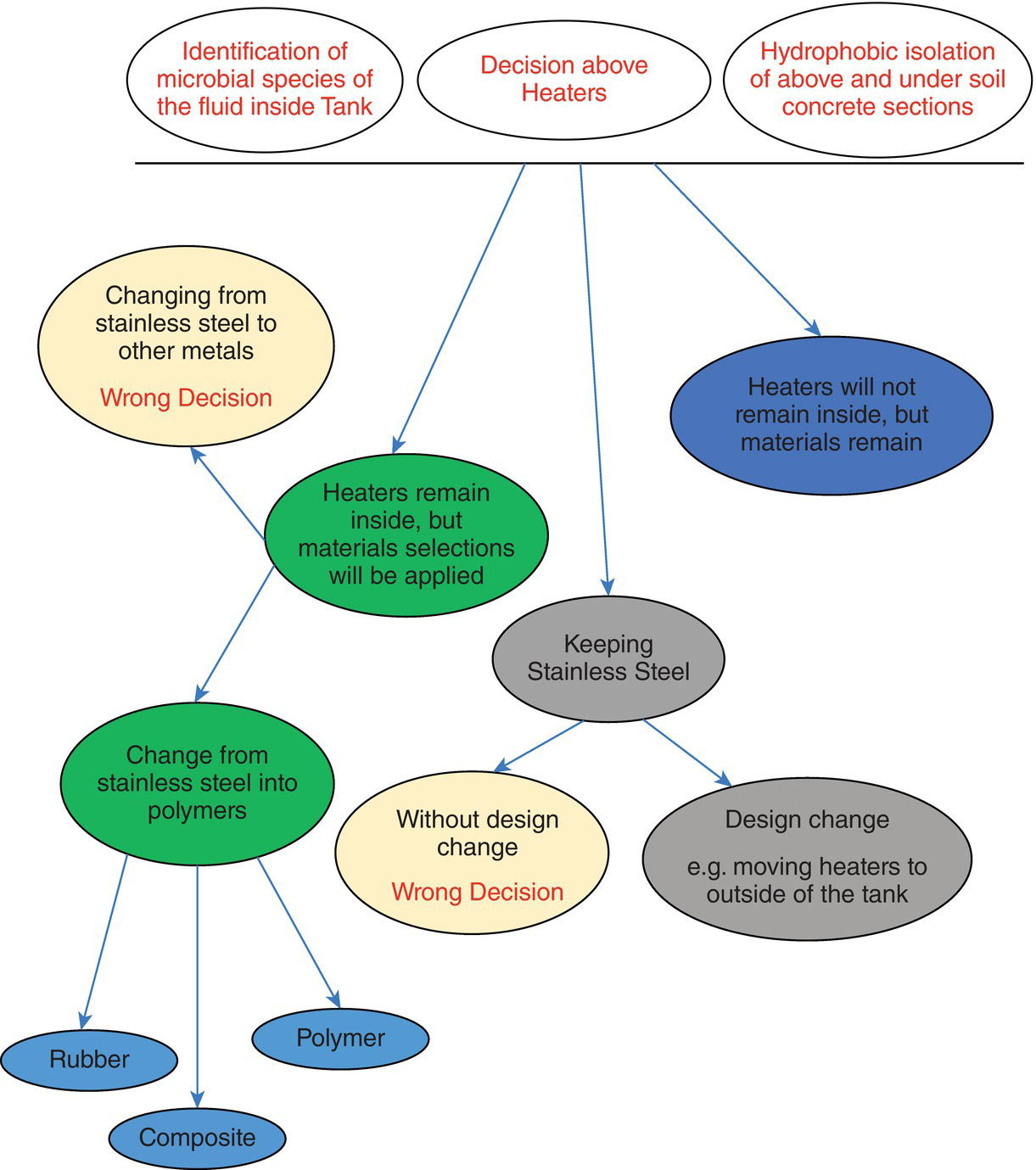
Figure 3.13 Decision tree for corrosion management of a bioleaching tank based on a CINS approach.
3.1.5 Phase 2: Application
In this phase, the measures to treat corrosion as per the previous phase are applied. Remedies whose application as corrosion treatment measures has been approved will be executed to the corrosion system in such a way that can satisfy the minimum three requirements below:
- These measures are feasible enough to be applied
- These methods are eco‐friendly
- They must be as easy as possible
The eco‐friendly requirement is particularly important, and often the above three requirements may contradict each other under tough production conditions that are being imposed on the industry sector, in which the corrosion system is being investigated. Economy and ecology of anti‐corrosion measures must be in place together to assure that the whole process of application meet the requirements of being called safe. A good example of such is replacing in‐use synthetic biocides with their natural counterparts. Although research about some plants and their detrimental impact on several microorganisms has been known for some years now, they are not in use on a large scale by industries due to many reasons that we will not discuss here.
Application is also an important issue because there must be a convincing reason why a certain application method is preferred over others. While feasibility and eco‐friendliness are both important, they are of no use if the application is not easy enough to be put into practice . Ease of application can quantitatively be measured with the time spent on it. If applying biocide takes less than applying coating, then biocide application is obviously preferred because of the economy involved in it.
Yet another issue that must be taken into consideration in application of anti‐corrosion measures is how well they perform. There must be milestones in place that will show how positive or negative the measures we have taken are acting. This is the topic for the next phase; Monitoring.
3.1.6 Phase 3: Monitoring
This phase, in short, consists of two steps:
- KPIs
- Finding the best monitoring technologies
As briefly mentioned previously, it is very important to realize how well the applied anti‐corrosion measure has performed. For this reason, it is important to define a measure against which the performance can be evaluated. This measure is what is often referred to as Key Performance Indicator . It is a measure that, when the obtained results are compared against it, it shows where the system is standing from a corrosion health point of view. It follows that to do the monitoring well, the first requirement is to have a set of KPIs. Certain standards can be used in this regard. For instance, to evaluate how severe corrosion is in terms of corrosion rates, or how serious corrosion is in terms of pitting, or the like there are many guidelines and standards that can be consulted with. KPIs show how and in which direction from as‐is conditions of an asset the CM consultant must act to arrive in to‐be conditions.
As there can exist parallel geometry for corrosion reactions already taking place in the system of corrosion, application methods could also be parallel and fit for each of the reactions. It is in this regards that possible antagonistic effects between these methods must be taken into consideration very seriously.
In addition to defining KPIs for the corrosion system for it’s as‐is and to‐be conditions, the way by which corrosion must be monitored is also important. A web search for “Corrosion Monitoring” standards will certainly yield in what a corrosion technologist will be looking for.
It may be useful to advise that if one chooses to apply a CINS approach, monitoring must be defined as per subsystems whenever applicable. In the example of the bioleaching tank we gave earlier, it is possible to define the KPI for the outer metallic body of the tank in terms of allowable corrosion rate where no through‐wall corrosion pitting will be likely to be experienced, nor will the entire mechanical integrity of the tank be sacrificed. For this, it is equally important to define KPI particularly for the internal coating. Having KPIs in place will also serve to get a sense about what to expect when the asset is being inspected during periodic overhauls.
Finally, we would like to once again remind our readers that all engineering assets are in their pseudo‐FFS states and therefore it is very important to have KPIs in place, because in comparison with them the healthy condition of the asset will be evaluated.
3.1.7 Phase 4: Feedback
It is in this phase that the following must be carried out:
- Feedback about the results of application phase
- Re‐application if the feedback is not desirable
- Sharing the acquired knowledge and skills
- Documenting the overall results in the form of recommended practice
Importance of Phase 4 is that it will allow others (next generations who will be recruited in the plant and current colleagues in your industry or similar industries who are sharing the same corrosion problem) to get a feeling about how to effectively rectify their problems.
Phase 4 is also a feature of Javaherdashti CM model that has not been addressed in many CM models. It seems that the ultimate goal of current CM models is to recognize the problem, find the best solution in terms of applicability and cost, and rectify the problem in as short a time and as cost effectively as possible. There is no plan B about what if the solutions provided did not work or what are the steps (to be documented for each plant/industry) that are necessary to share the information gained. Here we would like to mention that in our opinion, there is a vast difference between “data” and “information,” as we can simply put as the following; raw information is data and processed data is information. It is not necessary to include all the figures and values one has obtained regarding the phases that have been applied, the overall picture would be enough. In addition, there must exist a procedure that what fraction of the gained information can be seen as lessons learned. This is a very important step, and if there is no legal framework for that it can lead into serious, unwanted results for the person(s) who are transferring the information in the form of a research paper, or as a part of a technical chat on social media.
It may be necessary to also explain what is meant by “re‐application” within the context of this chapter. It is quite possible that the treatment measure(s) approved to be applied will not work when compared to the pre‐determined KPIs. An example as such is if the wrong corrosion inhibitor3 is applied, the wrong dosage of a correct corrosion inhibitor is used, or the applied coating/material is not what it needs to be, and so forth. This will require going through previous phases, particularly Phase 1, to make sure that the corrosion processes and their geometry already active in the system have been picked up correctly. It is obvious that if the corrosion reactions and the way they interact with each other (series or parallel) are understood correctly, then chances are that the treatment strategies to be applied will work.
The Javaherdashti CM model may be stopped when it comes to Phase 2, particularly if the business owner has found out what his corrosion problem is and how to address it. An important issue for the business owner or the operator could even be how the corrosion problem can be addressed in a short time. This mentality is understandable because most of the time, the operator is under the pressure of production and commitments associated with it, and may not want to researchwhy the suggested remedies have worked and how they are going to publish a paper from the information (Phases 3 and 4). As long as they see that the suggested remedy worked well enough to allow them continue their production with a reasonable level of reliance, they (the business owner of plant management or operators) may not be interested in taking the CM business further unless the corrosion issues will have a vast impact on the ecology and/or economy of the production, or shorten the service life of the asset dramatically and bring it much closer to Zugzwang effect state should corrosion continue.
Therefore, it should not come as a surprise if any CM model is advised and even published, but remains half‐executed due to many reasons. One of these reasons could be pouring the budget previously assigned for a CM project to an immediate case of COVID19 treatment or consequences associated with it (such as, but not limited to, having less workforce to carry out the required jobs).
3.1.7.1 Corrosion Cost Estimation Model
Thus far, we talked about technicalities that must be involved in any corrosion related matter for which a CM model is either to be developed or applied. However no CM model will be completed if there is no clear approach for considering the economy of the damage imposed by corrosion.
The importance of having a corrosion cost model in place is that it can largely serve to justify the costs associated with dealing with corrosion. These costs range from those are related to exploring corrosion and root cause analysis to finding the best treatment method. In all these scenarios, it is essential for the business owner to justify why these expenses are necessary.
While some economical aspects of corrosion will be discussed later in this book, it is essential to have an idea about what is currently available as the toolbox necessary for researchers and investigators, particularly concerning estimating the cost of corrosion. Details of such models have been given in part in several publications [15,21–27].
Research about the cost of corrosion dates back more than 70 years; the cost must be expressed based on a measure that is a common denominator of all economic parameters in a country. It is obviously not reasonable to base the cost estimation model upon variable parameters that are not the same for developed and developing countries. However, the common outcome is that the cost of corrosion is expressed as a percentage of GDP (gross domestic product) or GNP (gross national product) of a given country. The cost of corrosion can be expressed regardless of the differences existing among countries; for example, if in country A the cost of corrosion is 3% of its GDP and in country B the cost of corrosion is 5% of its GDP, it does not mean that A and B have the same GDP, it simply shows how much of their wealth is being consumed by corrosion.
There are basically four models for estimation economic cost of corrosion as follows:
- Uhlig Model, named after Dr. H.·H. Ublig, this model has features such as:
- It is rather a conservative model that gives minimum values for corrosion costs.
- Its basic assumption is that direct and indirect costs of corrosion are equal.
- Initial data to construct the model are taken from producers and not consumers.
- This model cannot express the corrosion cost distribution scheme within a given industry, nor can it calculate how much a certain industry can save on CM.
- This model does not present any particular method to calculate indirect costs of corrosion.
- Data collection is carried out by submitting questionnairs.
- This model has been used to calculate the cost of corrosion in the USA, India, Japan, and China.
- The Hoar Method, named after efforts organized and conducted by Dr. T. P. Hoar has the following features:
- In this model, input and feedback on corrosion costs are inquired from both industry experts and academics.
- Hoar model is industry‐based.
- Direct cost of corrosion as calculated by Hoar model is always higher than that calculated by Uhlig model.
- No clear methodology to calculate indirect cost of corrosion.
- Data collection is carried out by submitting questionnairs.
- This model has been used in the UK, Japan, and China.
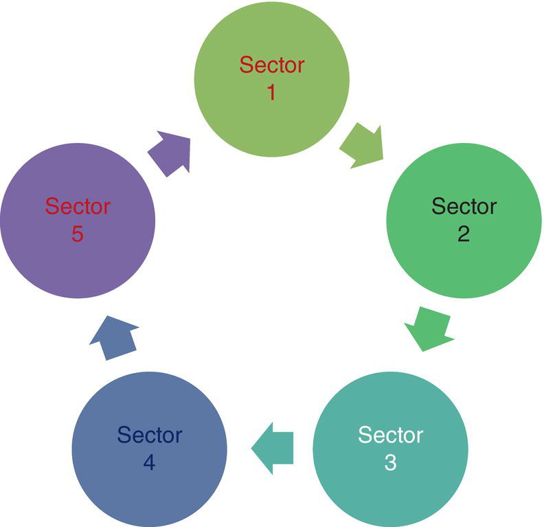
Figure 3.14 Simplified schematic presentation of I/O model, where the output of each sector is treated as the input of another sector. An example is that the output of mining industry as coke is treated as the input for steel making industry. The output of steel industry as galvanized steel then will be input to automotive industry.
- Input/Output model, also known as I/O model can be schematically shown as in Figure 3.14.
Some features of I/O model are as below:
- There are uncertainties about both the capital cost and intermediate outputs.
- For each industry sector, the tedious job of calculation of cost coefficients (the coefficients that show how different sectors are mathematically interrelated) is required.
- Despite the complexity of this model and difficulties associated with it, it is claimed that for a country like India, feeding the inputs for four decades into such a model has yielded a simple equation that can calculate the cost of corrosion in this country for each year required.
- There is no particular methodology to calculate indirect corrosion costs other than inter‐sectors costs.
- This model has been used in the USA, Australia, India, Japan, and Turkey.
- LCC analysis, has the following main features:
- Compared to the previous three models, this model appears as more realistic.
- LCC model is applicable to calculate cost of corrosion in equipment, structures, and factories.
- Applying this model to India has always demonstrated cost coefficients lower than those obtained by applying I/O model.
- This model is not suitable for considering all factors and parameters involved in indirect costs of corrosion due to the ever‐changing, dynamic nature of interactions among variables related to the indirect cost of corrosion.
All the models discussed above have their pros and cons and it would obviously be a more thorough approach if at least two of them are used together for one corrosion case and the results compared. In addition, it must be noted that these four models discussed earlier do lack a clear methodology to quantify the indirect costs of corrosion. This is a very significant aspect of these models that must be taken into consideration when these models are to be employed for any management of corrosion approach.
3.1.7.2 Corrosion Knowledge Management (CKM)
An integral part of a management of corrosion program is to have a plan ready to allow us to measure, either via quantity or quality, the impact of management parameters on the way corrosion is being treated.
We introduced CKM over two decades ago. CKM is a managerial tool specially design to advise managers with little or no technical knowledge of corrosion about how to deal with corrosion as an issue in both the present [28–31] and future [32] states of their industry.
While CM deals with the risk of corrosion, CKM deals with the management side of it, which also includes the economical/ecological impacts of corrosion. We have explained the similarities and differences between CM and CKM elsewhere [33].
The main algorithm to be followed regarding a CKM‐based approach is as per the steps below:
- Step 1: As per the industry and the plant to be investigated, at least two of the four internationally acceptable corrosion cost models are selected and applied;
- Step 2: The outcomes of the models are compared, and the range of corrosion costs is determined;
- Step 3: The findings are reported to the business owner/high ranking manager;
- Step 4: The impact of cost of corrosion is measured against seven management parameters.
In applying the steps above as per a CKM scheme, a suitable CM approach must also be taken. This CM approach may opt to use any CM model available, from the CM model suggested by BP to that suggested by Total and the like. As we have mentioned earlier, a CM approach as such will be a technical matter and has been discussed in previous sections.
However, regarding the steps mentioned above, Step 4 needs to be explained in more detail; in fact, we need to specify what these seven parameters are and how they are (or can be) related to a CKM model.
The seven parameters of management are as follows.
- Budget: When based on a combination of economy models related to the estimation of cost of corrosion, it was found how significant the cost of corrosion in the plant is, then it is decided how much it is logical to expect this cost to be lowered. It must be noted that as corrosion is thermodynamic, it is impossible to bring the corrosion cost down to zero. It is generally believed that up to 37% of the cost of corrosion can be recovered. Therefore, the remaining (or a percentage of the remaining) estimated recovery cost must be taken by the management as the budget necessary to manage corrosion. As an example, if in year zero, the economy models showed that for a particular plant the cost of corrosion is, say, $100m, then it must be planned to bring down this cost to, say, $70m. It is possible to take, say, $10m as the required budget to manage corrosion to save on later corrosion costs and have a net profit of at least $20m. We take it as self‐evident that saving $30m cannot be expected to happen overnight and it requires careful planning (as per reference [16]; in Kuwait cost of corrosion in 1987 was 5.2% of the GDP, and was lowered to 1.7% of the GDP in 2011; it took 24 years for this country to lower cost of corrosion by 3.5%).
- Human Resources (Expert Team): Based on management decision fighting against corrosion where management becomes serious enough, a team of experts will be necessary. There are three ways to handle this requirement; (i) employing corrosion experts (ii) employing an experienced consultant, or (iii) training the existing staff without going through the costs associated with previous options. If options (i) or (ii) are to be selected, for each or both options there may be a need to find the best possible solution as per existing regulations, based on the emergency of the case. In some countries, it may not be easy to create a position for a corrosion consultant to a refinery or a power plant simply because there is no position defined. It is then very important to bear in mind that any CM model that will neglect such cultural facts is to be doomed as a global recipe to treat corrosion.
- Training Department: It is always a familiar policy by the industry to cut the expenses that may seem extra. It is quite expectable for a company not wanting to employ new person power or consultant(s) simply because it is seen as an extra cost. It is in this regards that training of existing staff may be put forward. The training department must then be very sensitive to the training programs it is planning, because most training departments have a passive rather than active role; they do not advise or publicize the available courses, but prefer to work based on the feedback they receive from the personnel. An example is that the training department may never think that a course in galvanic corrosion (particularly galvanic corrosion, CUI, or atmospheric corrosion) is necessary for their colleagues. The most they think of is to offer a general course in corrosion. The duty of the training department is to continuously seek new topics of interest and use to the present and future operation scheme of the plant, not just wait until they have a request. To avoid and prevent any industrial nepotism, the required topic and industry skills both must be required. Our readers must note that the instructor is being called for an industry case which is far different from an academic research interest, therefore the invited trainer must ideally have both academic qualifications and trackable industry experience. One may not have very distinctive academic degrees (a BSc will suffice), but in return they must have at least 20 years of experience. Dealing with various corrosion processes does need a robust theoretical background, for example, not to call microbial corrosion as water corrosion, asbitterly reported by Tatnall [34].
- Research (University‐industry Gap): It is a bitter fact in many countries – perhaps with the exception of some Western countries – there is a huge gap between academia and industry, especially when it comes to corrosion. This author firmly believes that, at least in the field of corrosion, it is the industry that must be the leading force for research. Even very advanced research must come from industry needs and not just out of curiosity. Therefore, for a given plant it is necessary to be backed with a robust research scheme that will not only clarify corrosion reactions involved but the geometry among them. One very essential tool in conducting research is using TRIZ; the concept of TRIZ is discussed in Chapter 5 of this book, however what can be very briefly said about TRIZ is that it is an algorithm for innovation. By learning TRIZ and its principles, methods, and laws, the likelihood for achieving innovative results will be highly increased.
- Information: There is a vast difference between data and information, as we said earlier. To process the data obtained from field measurements and convert it into information useful enough to create an idea about the current status of the corrosion system and what must be done about it in the future, both updated theoretical knowledge and field skills are needed. In addition to this aspect of information, it is vital to have a written procedure in place to lessen “dark information” and increase “white information” [5]. Dark information is the knowledge and skills hidden in people's minds and their own notes, and therefore so personalized that access to it is impossible (or too difficult) for others to understand. White information, on the other hand, is what is written and accessible by everyone. An example of dark information is verbal information, and examples of white information are standards, recommended practices, and the like. To deal with corrosion, the information must be shared and easy to access so that no time will be wasted on activities that can be branded as re‐invention.
- Energy: In this context we use energy equivalent to motivation. Management has to deal with people and as such, they need to be motivated for the job they are going to do. It is necessary to motivate the people involved in the management of a corrosion scheme to feel that no matter their expertise – whether technical, such as engineering or non‐technical, such as management – they are part of a project that is very significant. Perhaps one way of doing this is to ensure them that if next year there is a decrease in the cost of corrosion, they will all receive a bonus! Any measures that can be used to serve the target of getting motivation and so‐called positive‐energy is of extreme importance, as there are at least nine components of a working place that will render it stressful to the employees (Figure 3.15).
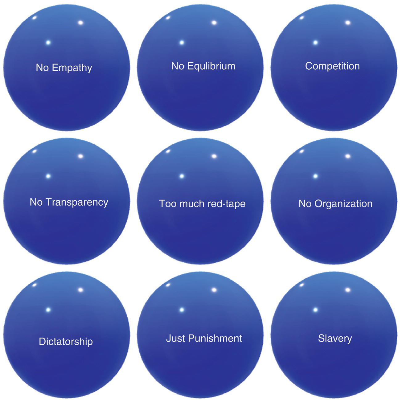
Figure 3.15 Components of an unsuitable workplace.
The nine components that can cause restlessness and stress in a workplace can be described as below:
- No Empathy: Managers are disconnected from their employees in terms of not being able to relate to them. The wall around mangers will not allow their employees to feel attachment toward their managers.
- No Equilibrium: Working hours and family hours are not recognized. There is no distinction regarding non‐working hours for the employees, so their private lives can be severely affected by the long hours and what is imposed on them.
- Competition: In this context, competition must not be viewed in its positive meaning. The positive meaning is when employees are in competition with each other for the good of the company. Here, however, competition is between employees themselves where methods used are not healthy. Competition in this regard can be lead to the collapse of the company, as does not aim toward advancing the company, but against other individuals.
- No Transparency: There is no transparency about responsibilities and what is being applied. No one is aware who is doing what and who to go to for an explanation. As the responsibilities are not well defined, there is no way to distinguish where one's responsibility begins or ends.
- Too much red tape: There are so many rules, regulations, and procedures that in reality what they do is lead to confusion. There is no opportunity to let people think and act freely, and the boundaries serve more to limit them than providing clear responsibilities.
- No Organization: Everyone does his work in the way he thinks is correct. There are basically no measures that define where and when a job or a responsibility starts and how it must be carried out.
- Dictatorship: In an unhealthy workplace, what the managers say is the law and everyone must follow. There is no room for critical thinking or constructive criticizing. The manager orders and then does not bear the responsibility for issues, and no one is allowed to question their decisions.
- Just Punishment: One of the ways by which motivation can be constructed or re‐shaped in accordance with the needs and aims of the company is by a reward‐punishment system. Employees are promoted or receive a bonus for what they do that is favorable to the company, and are punished (such as fined, delaying promotions, or being fired) for what they do to harm the company, whether consciously or not. However, if instead of a dual reward‐punishment system, we rely only on only one system, the employees will soon find their working conditions unbearable and will look for opportunities elsewhere and possibly sue their previous workplace.
- Slavery: There is no defined relationship between the management and the employees so that management behaves with their employees in any way they wish. More or less, the management assumes that their employees are like slaves to them; they may talk down to them, treat them poorly, or as lesser than themselves, whether skilled or not.
The nine components above may seem somewhat exaggerated, especially to Western readers, but this author can assure his readers that his presence in many industries around the globe have proved to him that these issues do exist.
While the nine components shown in Figure 3.15 can be related to any activity in which human beings are involved in a workplace, when it comes to CKM it becomes even much more important. One thing which often seems to be forgotten or overlooked by integrity managers and CM professionals when it comes to management of corrosion, and is a very important factor in this context, is how the members (both technical/engineers as well as technical/technicians and non‐technical, administrative colleagues) of the plant and/or company at which CKM is to be carried out need to adjust themselves concerning having knowledge about corrosion, however small or limited this knowledge may be.
The issue of corrosion within a context related to CKM is like knowing first aid; you don't need to have in‐depth knowledge of medical skills but you need to know just enough to see the essential needs. All personnel must be trained about corrosion and they must go through a carefully designed motivation system. While the level of education will be different for an engineer than an office clerk, it is something that must be determined by experts and fairly discussed with the training department of the plant/company, but the motivation program is something that would definitely require the help of an expert in this field. This expert most of the time is not an engineer but a psychologist with intense experience about people working in industries.
- Time: What is meant by the context of time is not just completing jobs on schedule, but the entire plan. It is very important to know that a CKM scheme must start from year zero and go on for three years, at least in phases. The entire timing of the project should be like the one presented below, Figure 3.16.
The model suggested here consists of three territories:
- Blue territories: Phase 1 to Phase 4. In this territory, preparation for selection and application of corrosion cost models, as well as data acquisition and analysis to arrive at information are performed. What is meant by information here is a figure that shows direct cost of corrosion for the plant.
- While territories: In these territories, that are alternatively called waiting periods of 24 and 36 months, recommendations suggested by experts for lowering corrosion costs are applied.
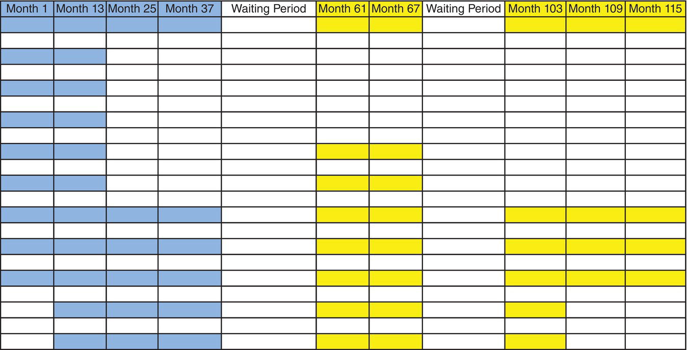
Figure 3.16 An example of a 115 month CKM scheme. This scheme is arbitrary and based on the CM culture that may exist in the plant, the overall duration may become longer or shorter than time milestones shown in the figure.
- Yellow territories: These are the periods during which the recommended CC strategies and tactics, and the results obtained from them, are examined and analyzed.
In more detail, the following can be said: phases of the CKM scheme given in Figure 3.15 are:
- Phase 1: Selection of the economic model(s) (1 month).
- Phase 2: Preparation and modeling based on provided data (12 months).
- Phase 3: Application of the model(s) in terms of data collection (12 months).
- Phase 4: Quantification of the data into information (12 months).
The above four phases (Blue territory) as mentioned above deal with selection, preparation, application, and results.
After phase 4, there must be a waiting period that we have chosen for our model to be two years (24 months). During the waiting period, within six months (month 61 to month 67), re‐measuring corrosion cost model(s) is carried out. This is Phase 5 and is shown in yellow; Phase 5 can be called short‐term feedback. It is during this yellow territory that the initial results of recommended measures against corrosion are taken into consideration and their effects on corrosion cost are being evaluated. In these periods, it is possible to re‐use the models that were developed during the blue territory. To keep repeatability of the models and consistency of the results, it is advised to use the same models used for the blue territory for the yellow territories.
Phase 6 starts right after the quick feedback period and is a waiting time of 36 months. Phase 6 can alternatively be called mid‐term feedback. Phase 6 is important in the sense that during this phase the assets are still in their pseudo‐FFS state and the assumption is that during Phase 5 have all been applied. In other words, if the equipment has survived the short‐term feedback period and Phase 5, then this implies that they must have been in conditions good enough to have arrived in the mid‐term feedback phase.
Phase 7 is a 12‐month period, dedicated mainly to documentation and final report preparation based on the results obtained from the short‐term and mid‐term feedback periods. Each feedback period will serve to show if the CM practices performed had any effect on corrosion cost as a part of a CKM scheme.
Although the two white time phases of 24 and 36 months are included in the entire scheme of a CKM project, they are excluded from it from a cost‐management point of view. Therefore, the actual timing of the project in this example, not counting the waiting periods, will be 54 months or 4.5 years.
It is essential to note that changes to be made to seven management parameters must be done after short‐ and mid‐term feedback periods.
For a typical project as such, the help of economists is necessary in addition to engineers. In addition, ecology experts will be needed if indirect cost of corrosion (for example limited study on the impact of corrosion on environment) is also to be regarded.
Obviously, the example given in Figure 3.15 is based on several assumptions that may not be true for a given plant. For example, based on the existing corrosion awareness culture, the time length of each phase can be shortened. However, it is strongly advised not to omit the waiting periods. These periods can be made shorter but they must included in such a way that they take at least six months.
CKM has some features that need to be addressed here:
- CKM is to be useful mainly for Greenfield projects which are in their pseudo‐FFS conditions and thus already experiencing corrosion.
- CKM looks on both economic and ecologic sides of corrosion and therefore contrary to any CM scheme, a CKM scheme could take much longer. The main reason for this is in very few plants worldwide it is possible to find a corrosion cost scheme that has been advised by economists and executed by engineers. Equally rare is to find an ecological model for a given plant in which corrosion and its role has been highlighted.
- CKM like CM is a part of a more encompassing management of corrosion program. The feedback taken from CKM studies, in both economy and ecology, must be carefully taken into consideration. Management of corrosion is a holistic approach and being as such, it requires that its framework also considers not only technical aspects of corrosion (such as research) but also non‐engineering aspects as well, such as issues related to human resources and training.
CKM has four principles:
- Principle 1: Corrosion system definition; this topic in terms of being able to define CINS and/or COFS has been covered previously in this chapter.
- Principle 2: Transparency; this is a legal side of CKM. According to this principle, the business owner as well as the consultant or the project manager for a CKM project agree to reveal what aspects of finding to the professionals outside of the plant and the common people who have no technical information or background about the consequences of corrosion in terms of the costs it imposes. If the outcome of corrosion in terms of environmental impact is something that would affect people living nearby, there must exist regulations that would clearly determine how the obtained results from a CKM approach become known to others. In this regard, while CM could be an internal affair of the plant or company, CKM has both an internal affair side (rearranging of seven management principles in terms of making corrosion cost more affordable) and an external affairs side (how to share the findings with other colleagues working in the same industry as well as how to deal with the information gained in terms of legal and publicizing terms). It is a bitter fact that in some countries, speaking about the extent of corrosion‐related catastrophes is taboo. This is even true for some Western reputable companies (the way some high‐ranking managers reacted to the oil spill disaster in Prudhoe Bay, for instance). For example, water authorities are using many cast iron pipes for carrying drinking water, and this water is also to be disinfected by hypochlorous acid. Recently [35] it has been discovered that upon reaction with the disinfectant agent, cast iron releases toxic compounds of chromium that could lead to serious health problems such as cancer. What should the water authorities do with this finding? Can they share it with their colleagues? Can they share it with potentially affecting people? If the answers are yes, then to what extent must this sharing process continue? If this water authority company had been located in another geography, could we expect not to even hear about the problem and the possible underlying corrosion mechanism in the first place? It is because of these and similar questions that we believe having a CKM scheme along with a proactive CM is an essential part of any management of corrosion program that wishes to be taken seriously and become successful.
- Principle 3: Use of Information; although we have previously discussed about dark and while information types, it is also worth repeating that a CKM scheme must also look at creating a systematic use of existing information (both dark and white) as well as creating information accessible to everyone, as per protocols and regulations.
- Principle 4: Modeling; what is meant by modeling is that the CKM scheme must have the potential of using mathematics in order to construct mathematical models that later on could serve as the main platform to produce specialized software. While modeling certainly has limitations such as, but not limited to, the necessity of making assumptions to make the mathematics simple enough to become applicable to the system to be considered, it certainly has undeniable advantages in explaining the present state of a system and predicting its future. Assumptions, such as initial and boundary conditions, that are necessary to make a model may seem to simplify the system – and this is one of the defects always brought up by many – it is also an important feature of any mathematical modeling procedure.
Below we will introduce a mathematical procedure we have developed based on the mathematical modeling work by Schouten and Gellings [36]. This model introduces a mathematical tool that is called Corrosion Protection Factor, or c.p.f. The model can be applicable to any given CM approach to evaluate the usefulness of CM techniques frequently used. We have explained this model and how it can be applied elsewhere in one of our previous publications [12], but due to its very important features we will very briefly discuss the main features here.
Schouten and Gellings model, or as we have briefly named it, S‐G model, looks at quantifying the best CM practice in terms of a mathematical algorithm that will combine frequency of use of certain CM measures (such as cathodic protection, coating, use of chemicals, etc.) with expert opinion of how useful these methods are when applied to a certain case of a corrosion system. In the example we have discussed in reference [12], we used a subsea pipeline example on which five CM measures, namely cathodic protection, coating, corrosion allowance (in terms of getting a “thicker” pipe), application of inhibitors, and application of biocides had been suggested as the main measures. Three experts are asked to evaluate both the usefulness and frequency of use of each method by answering a questionnaire. Based on overall opinions of the experts they are branded as optimistic, moderate, or pessimistic. For instance, the expert being branded as pessimist may have been of the opinion that most of the CM measurements are useless, less useful, or not frequently used, and the like. These opinions are quantified and certain c.p.f. percentages are calculated. The obtained c.p.f. values are matched with NACE references that define low, moderate, high, and severe corrosion categories, and based on that the average of c.p.f. values we calculated and compared with required ranges for which a given CM scheme can be called effective. In the example of the subsea pipeline and the CM measures taken against MIC management, the overall score of c.p.f. was 73.5% that corresponded to a “moderate corrosion management scheme.”
Based on the c.p.f. model above, the CKM scheme can decide how well the applied corrosion measures are in inducing corrosion protection, and thus their effect on overall direct cost of corrosion. The costs imposed on the system by the available corrosion measurement methods and the level of protection they offer will then be an important decision‐making factor in choosing the most feasible corrosion protection option. This, when joined by the impact of corrosion cost, can yield in a multilateral approach toward corrosion in a plant or in any given industry.
An incredibly significant side of any CKM is to have a say regarding indirect costs of corrosion, of which cost to environment could be the most significant. In our previous works [5, 12], we have tried to address an approach that will fill the existing gap between corrosion specialists and environment experts. Despite all these, there is no model that can be used to describe the present state of the environment when the assets are in their pseudo‐FFS state, to the best of our knowledge.
However, we believe it is necessary to explain a point that can result in confusion; study of environmental factors on atmospheric corrosion, for example, is not what is meant in this context by the mutual impacts of corrosion and environment. As reported by Mattsson [37], ISO 8044 defines corrosion as “Physicochemical interaction between a metal and its environment which results in changes in the properties of the metal and which may often lead to impairment of the function of the metal, the environment, or the technical system of which these form a part … [where] this interaction is usually of an electrochemical nature.” Based on this definition, corrosion can also induce changes (impairment) to the environment. It is then this aspect of corrosion that has its impact on environment, that must be taken into consideration as a model capable of explaining the present and predicting the future of environment components (water, air, and soil) in terms of the effects corrosion can create on them.
While in our opinion a very important item in calculating the indirect cost of corrosion is its imposed costs on the environment, there are obviously other cost items that can be included under indirect cost title, such as but not limited to, overtime of production or overdesign [11]. There are also items whose costs must be included in any corrosion cost model. Normally, it is assumed that the indirect cost of corrosion is roughly equal to its direct cost; obviously, this is an incorrect assumption. To further illustrate an example of indirect cost of corrosion and how complicated it can be take the below example.
It is known that every 90 seconds one ton (1000 kgs) of steel corrodes, and to produce 1 ton of steel, between 6 to 7 tons of water is required [38]. It is then not too candid an assumption if we assume that every 90 seconds, 6000–7000 kgs of water is being wasted due to corrosion. This figure means that within one year more than 2 m liters of water per kgs of steel are lost due to corrosion. Obviously, the amount of water which is used for steel production, i.e. 6000–7000 kgs (liters) of water cannot be changed. However, the more we save on the water per kgs of steel corroded, by reducing the amount of corroded steel we will obviously save in wasted water. The cost thus saved (or rather, in case of inappropriate management of corrosion scheme, the cost thus imposed on the system) is also an indirect cost that corrosion can be lead to.
Any model that is to handle the indirect costs of corrosion must also take into consideration the very complicated nature of these costs. It may be wise to first simply choose one area in which an easily workable model can be developed. For instance, if the model is to quantify the corrosion impact on ecology, it can simply concentrate on its impact on only one component of environment; for example, water and as a subcategory, only seawater. The model may, for example, try to relate the number of failures in which corrosion has been documented, to be a major player with the existing models that consider the effect of such impacts on how seawater is being affected. An example of studying the impact of a regular CM measure (cathodic protection) on the marine environment [39] or similar studies, can be taking the required building materials to create an assessment model to consider indirect corrosion impacts (including costs) to be modeled and calculated.
3.2 Management of Corrosion and COVID19
These days our world is struggling with Corona virus pandemic. COVID19 has affected all aspects of life, including our private and professional lives. Meetings and seminars are now being conducted with the use of cyber tools, so that instead of having physical workshops and meetings, virtual meetings are becoming part of our schedules. Some of typical measures taken by industries against COVID pandemic are as follows.
- Limiting contact with clients and suppliers and diverting such activities to digital tools wherever possible.
- Observing social distance regulations wherever face‐to‐face meetings are inevitable.
- Division of departments within a company to minimize the contact between the employees at inevitable occasions (such as breaks).
- Minimizing the number of people simultaneously being present in each confined space.
- Encouraging remote working when possible.
- Increasing hygienic measures in terms of cleaning and disinfection of all general contact surfaces and areas.
- Temporarily suspending all foreign trips.
Consequently, management of corrosion and its components in terms of CM and CKM are also being affected. The big challenge, particularly for corrosion industry, seems to be deciding which is more important; investing corrosion mitigation methods and technologies, or dealing with taking precautions against COVID19 as imposed by governing bodies.
The corrosion science community has already started academic work on the possible impacts of the COVID19 pandemic on the corrosion of materials in terms of accelerating corrosion rates due to frequent use of disinfecting chemicals containing chloride ions [40]. In a CM approach which is based on Javaherdashti CM model, a paper [40] is accommodated in Phase 1 which is the phase for definition. In this phase, possible expected corrosion scenarios are discussed for a case where anti‐covid and anti‐corrosion measures are to intersect, and having a clear Phase 1 is necessary as it will guide us on how to define the applicable, feasible, and available measure against corrosion. In our CKM approach, as one of the most important factors related to management of corrosion and being pro (not opposed to) CM, the important role of motivation, human resources, and training have been mentioned, and undoubtedly they are very significant parts of the larger issue of management of corrosion.
An integral part of management is dealing with human beings, and being as such it is important to also consider what can affect them. COVID19 is a crisis that has been affecting all aspects of life and activities including corrosion protection industry. It is in this regard, that human resource becomes of tremendous importance. As J. Eskenazi points out in his note “4 Things That Don't Change for Recruiting and Hiring During A Crisis” [41], these four essentials are:
- Communication
- Clear expectations
- Keeping interviews going
- Being ready to share
While the above points’ main audiences are recruiters and hiring engines, they are also applicable to your company's present, existing, human resource, that is, your employees. The employees in this context are both corrosion‐related professionals and, seemingly remotely corrosion related people who are supposed to have no ties with corrosion issues at all. The first includes engineers and technicians working at maintenance and/or any department related to corrosion protection (such as cathodic protection or water treatment). The second will contain professionals who work in relation to process, and the third will be related to people working in departments such as human resources and accounting, to name a few. These people need to become ready for the upcoming changes due to restrictions imposed by the pandemic. Currently what most companies are doing is encouraging their employees to work from home. While this may be a temporary remedy, it does call for having a suitable infrastructure that would support all the services required from webinars (on‐ or off‐line) to virtual seminars and kick‐off meetings. However, the obvious point is that the operation of the plant cannot be carried out virtually, and even if the operation would become as such, the corrosion problems that would arise do require to be addressed by physical presence. This will require having an interactive, viable, and robust network of all the people involved. To design this network, I believe the four essential elements put forward by J. Eskenazi will also be applicable.
If COVID19 is to be included in any CM of corrosion scheme, there are a few questions that the plant/company that wants to apply management of corrosion under COVID19 conditions need to answer, the most important of which are as follows [42].
- What is the emergency plan for the plant for working remotely?
- How can the plant management persuade the concerned experts (particularly regarding corrosion issue) to attend the virtual gathering sessions, including training?
- Study the effect of COVID19 on financial issues of the plant (as per instructions proposed by, for instance, international management consultants “Deloitte UK”).
It should be noted that the conditions imposed on working conditions by COVID19 can affect factors such as human resources, training, research, and energy, and when applied to CKM principles, all activities that are required to be controlled by experts attending the duty (for instance, preparing and application of procedures related to establishment of transparency) can be affected.
Getting back to Figure 3.12 that shows and summarizes steps to be taken during the life of an asset from its fresh state of FFS to its failure, it may be of interest to see how COVID19 or any other stressful situation of that magnitude that has a biological component attached to it can affect the life an asset.
The first step, as also stated in Figure 3.12, is inspection and issuing FFS by the inspector. The impact of pandemic on the inspector is a risk that cannot be belittled. Regardless of how small the likelihood, due to its serious consequences, the inspector must take the risk very seriously. In this regard, the inspector must observe all required conditions and take every precaution possible. The inspector must note that they will be in contact with many parts that could have the potential of already being contaminated; Corona virus has been reported to survive on metallic surface from two hours to a few days (on aluminum surfaces from two to eight hours and on stainless steel surfaces two to three days) [43]. Therefore, inspection to assess for FFS is a crucial step in which precautions against COVID19 is of vital importance for the inspector. When the asset is put into service and it is assumed to be at FFS stage, then it is corrosion engineer(s) and consultants who must monitor the condition of the asset. This will of course require many interactions that may take place via meetings, and it is during these physical meetings that the likelihood of contracting Corona could become high. It is then advised at this stage, to have an IT infrastructure updated and powerful enough to support virtual meetings as video conferences and live webinars, if required. It is also important to note that issues such as training will be accommodated in this step. The same precautions as just mentioned can also be applicable to pseudo‐FFS stage; in this stage, corrosion engineers and corrosion consultants will be engaged again. This, although not happening too frequently, is still of significant importance and must be taken into consideration seriously. Therefore, from a COVID19 consideration point of view, there is extraordinarily little difference between FFS and pseudo‐FFS stages.
CM can be affected by COVID19 too. If our CM model is such that involvement of human beings is necessary, then it is also of paramount importance to consider controlling measures for COVID19. CKM is an approach that is directly related to the involvement of humans. An example of such is anything that is related to gatherings (technical meetings) that will require serious precautions against COVID19.
The most important aspect of any strategy that aims at management of corrosion is to first have thought enough about the environmental factors that can affect the health of humans working in this project. If anything we do to rectify corrosion can have one atom of effect of improving the way humans are interacting with environment in the context of corrosion, it is worth it!
3.3 Environment
Corrosion has an important aspect attached to it that has not been studied in the way it deserves. While in one of our previous works [5], we tried to touch on this subject, it was too brief and like any pioneering work, there is much that needs to be done. Most corrosion related environmental impacts are expressed in a way that can be shown to be, at the best, the cause of the disaster. It is quite natural to express that such and such disaster happened due to leaking of such and such flammable gas or liquid, but how many wonder if the leak itself was indeed a result of poor management of corrosion (that obviously consists of both CM and CKM)? In addition, a very fundamental question in this regard is if enhanced corrosion in the form of leakage (through wall pitting) is the only way by which corrosion can adversely affect environment. There is currently no model or methodology that can be used to assess the environmental impact of corrosion on the three components of environment (water, soil, and air). Just to give an example, take the two examples below that give us a glimpse into how corrosion can have an environmental impact even without causing a leak.
For the first example, suppose that we have a buried pipeline that requires 400 A/y (Amperes per year) – to be supplied by impressed current cathodic protection – to be protected against corrosion. If we use the so‐called lead/silver anodes for this purpose with a consumption rate of 0.1 kg/Ay for a design life of 20 years, this will give an average mass of 941.0 kg of Pb‐Ag anode to be required for such an current output over the expected service life. Alternatively, this means an annual anode consumption rate of 47 kg (these anodes typically can have a mass balance of lead of about 93%). All this will mean that for this particular case of an underground pipe to be catholically protected, about 42 kg lead each year (or more than 115 000 mg per day) will be released to a component of the environment, which is soil in this case. This figure becomes more important when we notice that natural soils usually contain less than 50 ppm lead (about 50 mg lead per kg of soil). Therefore, by applying cathodic protection via impressed current for this pipe, each year the average amount of lead which enters into the soil is about 800 000 times its natural lead content. Multiply this by the number of pipelines that have (more or less) the same requirements, and it can be seen that huge amounts of lead are being pushed into the soil each year and thus poisoning it.
Regarding the second example, take an offshore oil platform that has been estimated to require 400 A/y for protection. For a useful design life of 15 years, and provided the use of aluminum anodes, during the design life of this platform more than 3800 g of aluminum will enter into the seawater on a daily basis. In our calculations, we have not considered other ways of metallic pollution (such as industrial wastes). If just one platform with the above working conditions can contribute to contaminating seawater about four tons per day, it is not farfetched how other platforms can do the same harm to the marine environment, especially knowing that there are currently more than 1400 offshore platforms around the globe. Therefore, environmental impacts of corrosion cannot be limited to issues regarding unexpected leaks; corrosion can slowly but surely impose its impact on pollution via quite normal CM practices as well.
How can these impacts be addressed in the most appropriate way? Apart from an urgent need for an environmental model of corrosion, perhaps a very effective way to address this issue will be looking at it from an organizational point of view.
Due to mutual links that exists in many safety/HSE accidents and near‐miss incidents with corrosion being the main cause, it is suggested to establish a Corrosion‐Safety Management (CSIM) Department with any organizational unit that is given the job of looking at CKM within a plant or a company that operates a company or a series of companies.
What can be shown as the necessity for establishing a CSIM Department? In any plant; regardless of whether the plant of interest is a gas processing refinery, a power plant, a steel complex, or anything of this sort in which corrosion can play a very significant role, corrosion can be a major role player in four issues.
- Corrosion in the main process equipment;
- Corrosion in the auxiliary equipment;
- Corrosion in the process safety equipment;
- Corrosion in the physical space in which the equipment (main and auxiliary) occurs.
To clarify the above four corrosion issues, let us take the example of a refinery:
- Example of corrosion in the main process equipment. The equipment in which various processes, such as but not limited to, distillation, refining, converting, and the like take place, are themselves vulnerable to corrosion. For example, corrosion could be a serious hazard in a furnace, in an Isomax unit, distillation tower, and other main process equipment.
- Example of corrosion in the auxiliary equipment. If this refinery has a base‐load power plant to maintain the required power to run the motors needed for the refinery, the power plant can be regarded as a very important element without which main processes can undergo difficulties in operation. Corrosion in these auxiliary units and equipment, then, is an incredibly significant issue. An example as such could be MIC issues in the cooling system.
- Example of corrosion in the process safety equipment. To manage the risk of fire, for example, fire water rings must be available to service and operate. One must make sure that these rings have not been clogged with corrosion deposits or there is no chance for pitting corrosion being developed under these deposits leading into the loss of the fire water. Therefore, the equipment that is to be used to maintain safety must also be considered, and suitable CM must be applied to them as well.
- Example of corrosion in the physical space in which the equipment (main and auxiliary) occurs. The concrete slabs, structural steel pipes, and the walls of the units in which the main and auxiliary equipment are sitting may also be vulnerable to various corrosion scenarios.
The above could also have safety and HSE aspects. A pipeline in which leaking has occurred because of development of a crack in the body of the pipe while within the pipe flammable /toxic fluid is being carried can create very serious safety and HSE threats to both the workplace and the environment. The root cause of the crack in this pipeline could be due to pre‐commissioning practices such as hydrotesting, or post‐commission operation‐related causes. In any case, while the root cause is related to CM, the environmental impact is to be handled by HSE and safety personnel.
All the above calls for establishing a department that will look after both corrosion and HSE issues and will study the risk, not only in terms of HSE risk, but corrosion risk too. This interdisciplinary department can be called as a Corrosion‐Safety Issues Management (CSIM) Department.
Who will benefit from a CSIM Department?
- The owner/management of the plant, whether from private sector or government sector. This is because by establishing a CSIM Department, the economic–ecologic costs to be imposed on the owner will be removed. The reason for this is that CSM Department will assess both corrosion and safety risks (likelihood and consequences).
- The workers of the plant. In addition to humanitarian reasons, it is necessary to save them from any loss they may experience such as losing their jobs because of injury or imposing costs on the health system.
- The environment around the plant. Soil, water, and air are the main elements of any environmental risk assessment. These three elements are also the main elements that corrode any physical structure; atmospheric corrosion can be linked to air, microbiological corrosion can be linked to both soil and water environments, cavitation could be a result of water hydrodynamics, and so on. The three elements mentioned above must be addressed to both control corrosion and contain safety hazards.
The required expertise for this department would be a team made up of both HSE and corrosion experts. The cause‐effect relationship between safety issues and corrosion causes must be studied and categorized. A risk matrix must be developed for all observable corrosion processes in any given plant.
3.4 Application of Management of Corrosion Scheme to Underground Fire Water Ring4
The case we will explain below is an underground fire water ring as shown in Figure 3.17
The alarming symptoms for the possibility of corrosion in this system are as follows:
- Observation of corrosion in external coupling system as suggested by high concentration of aluminum oxides, that upon visual inspection, appeared as white stains very hard to clean chemically.
- Observation of colored water upon discharge from hydrants.
- There are neither chemical nor microbial analyses about the water stagnant within the ring, or the soil surrounding the buried ring.
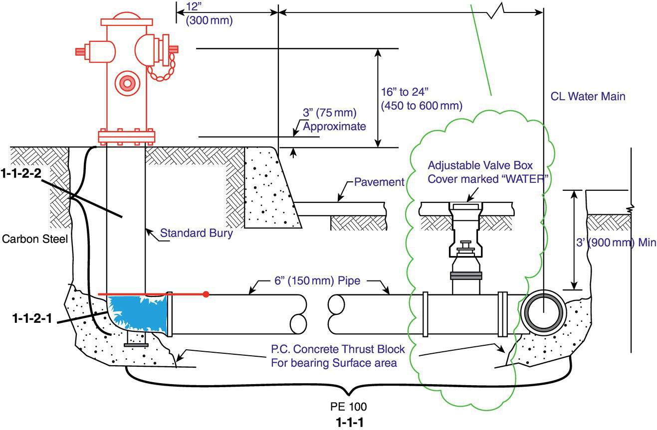
Figure 3.17 General schematic of a fire water ring as the corrosion system and the accompanying corrosion subsystems.
- No inspection of any parts of the ring since it started operation.
- As the water used in the ring is coming from a deep water well and no chemical treatment has been carried out (application of either corrosion inhibitor or biocides), the lack of data on present chemical and microbiological state of the water may both suggest that there is a possibility for corrosion.
Figure 3.17 is an example of CP and not CC. The reason is that although the asset (an underground fire water ring) has been in use for over one year and can still be considered as a newly installed and operated asset, it has not shown severe signs of corrosion, although some alarming signs as briefly addressed above. It is because of these corrosion signs that one could argue that corrosion was taking place, therefore setting the whole ring system vulnerable to corrosion. In other words, the asset is in its pseudo‐FFS state (it is being used despite showing some signs of corrosion), and we are going to apply a CP strategy so as not to allow the asset to approach the Zugzwang effect state.
The first step is that we apply a COFS/CINS approach to highlight the corrosion subsystems. A COFS approach will yield the classification below (Only important subdivisions are shown in the Figure):
1.1 The ring
1.1.1. Polyethylene (Pe) section
1.1.2. Carbon steel section
1.1.2.1. The elbow section
1.1.2.2. The steel section above the elbow and below the hydrant
2.1. The hydrant
Based on a color coding system, green showing the least expectable risk, amber showing medium risk, and red showing high risk levels, we will color code the corrosion subsystems identified above as the following:
1.1.1. Pe section (orange arrow)
A very good reason to replace metallic parts with non‐metallics, and particularly composites, is the high corrosion resistance that the latter shows. However, polymers may also be vulnerable to microbiological attack. The polymer used for this section is Pe 100. Pe 100 is a high‐density polyethylene (HDPE). To make it UV resistant, carbon black is used in its structure (for the particular case of the Pe used in this ring, the carbon black content is 2%). It must be noted that if polymers are treated to become UV resistant, they can also become susceptible to microbial attack [44]. While Pe may not be consumable by microorganisms, it must be noted that this polymer also contains carbon black, which can be used by microorganisms [45, 46] and it could be a vulnerable material by the action of bacteria existing both in the water and in the surrounding. Therefore, the main (possible) degradation5 mechanisms for this section could be microbial degradation from inside as imposed by the fire water existing in the ring and microbial degradation from outside as imposed from the surrounding soil.
1.1.2.1. (Carbon steel) elbow section (r).(Red Arrow)
It is in this section that stagnation of fire water mostly happens. Under the conditions existing in this section, the dissolved oxygen in water starts to scavenge over time [13]. This will allow anaerobic (oxygen‐free) conditions in which – based on the chemistry and temperature of water – growth and activity of corrosion‐related bacteria and archaea will be possible. This will prepare the grounds for inducing microbiologically influenced corrosion (MIC). It is also possible that anaerobic, non‐MIC reactions will occur. It is possible that non‐MIC corrosion can lead into enhanced MIC [47], therefore a series corrosion geometry may be the prevailing corrosion geometry.
It is of great importance to consider the issue of MIC in fire water ring system as it may lead to catastrophic situations if not properly taken care of [48].
2.1. The hydrant (yellow arrow)
Although this section is not in contact with the water, due to its very physical layout which is immediately above section 1.1.2.1 in Figure 3.17, its surfaces are being covered with water vapor coming from the stagnant water inside the elbow. This can increase the likelihood of corrosion in the form of electrochemical, uniform corrosion.
Looking at the possible corrosion scenarios in three main sections of the fire water system – the Pe pipe, the carbon steel elbow, and the carbon steel pipe below the hydrant – it appears that the main likely corrosion reaction will be MIC. This will finalize Phase 1 of Javaherdashti CM model, which is defining possible corrosion scenarios and their geometry.
Phase 2 will be highlighting what might be available as countermeasures. Normally and under these circumstances, there are some anti‐corrosion measures that can be thought of, for example, one may add suitable additives to Pe to make it immune to MIC, along with the use of biocides.
However, to do that, it is necessary to know the chemical and microbial composition of the water as well as the surrounding soil. It must be noted that while a material like Pe could be degradable by many microbes, these microbes may have not corrosive effects on metallic substrates. This is not a significant issue as long as the corrosion of the elbow is not important; in other words, there bacteria can exist in either the water or the surrounding soil that can serve to degrade and lose Pe. If they can do so, that means they can impose destruction to the fabric of the polymer and thus cause water leakage. It is also possible that corrosion‐related bacteria or archaea will not have any destructive impact on Pe, but be capable of inducing corrosion to the metallic elbow. The result will be the same, which is leakage of the water and depletion of the line from the precious water that would have been otherwise used for fire extinguishing purposes when needed.
The best that can be done is to find any bacterial/archaea species that can have any effect on accelerating the destruction of either metal (elbow) or polymer (line) so that the main result will be water leakage.
3.5 Damage Management
In the fall of 2020, at least three accidents occurred that did not find the place they deserved in the news due to the frenzy created by COVID19. A gas explosion and fire at a gas plant (December 2020, El Salvador); a massive fire at a refinery (December 2020, South Africa); release of poisonous material, and a massive explosion at gas station (August 2020 Russia). Of course, the list does not end here.
In a previous work [48] that focused on the role of MIC on fire management, we mentioned three stages:
- Management of the cause of the fire, (pre‐damage)
- Management of controlling/extinguishing the fire, (in‐damage)
- Post‐disaster management, (pro‐damage)
Obviously, damage is not limited to fire only. Damage can have a much wider meaning than fire, including leakages, mechanical failures, fractures, etc. Relating this to the concepts we discussed earlier, the most important is CP/CC. It means that it will make sense if at the pre‐damage stage any plans for CP or CC are executed. Where will an activity like failure analysis be accommodated? It will be in the post‐damage step whereby applying conventional standard methods of failure analysis, a root cause analysis report is made. This report will then help to construct the requirements that need to be applied to avoid damage in the future. If, for example, failure analysis showed that overheating was the cause of the damage, then our pre‐damage task needs to concentrate on measures that would either prevent overheating or control it as a potential corrosion‐inducing damage mechanism.
The main structure for a damage management scheme can be within the boundaries by which applying management of corrosion will make sense. In other words, CM and CKM components of a management of corrosion scheme both need to be defined within the executable frame of a pre‐damage step. It can also be safely said that the engineering involved in the pre‐damage step will be much less than that required in the post‐damage step; the amount of engineering work needed to assess and analyze the root cause of the damage is certainly greater when the damage has already occurred. This is an especially important factor that can be used to distinguish the division of labors between pre‐ and post‐damage steps.
The place pre‐damage approach has within a management of corrosion scheme will be explained in more details in the next section. However, it is significant to know that any cost that may seem to be imposed during the pre‐damage step will be highly paid off in the next two stages should the next stages (in‐damage and post‐damage) ever occur in the first place.
3.6 Algorithm
As we hope our readers appreciate, we have introduced in this chapter all the elements necessary to manage corrosion in terms of both technical and non‐technical managerial terms. To be able to transmit our approach more efficiently, we had to invent a new nomenclature of terms that, to the best knowledge of this author, are being introduced for the first time. Some of these terms are related to a new definition of failure not as a physical form of deterioration, but as an equivalent to what we call the Zugzwang effect status of the asset in its service life. We defined failure in this context not by the mechanical inability of the asset/equipment to do its job, but in terms of (1) repeating damages and (2) lack of economic justification for repairs. In doing so, we stated that each asset has to pass through three major steps; The first step is the Fit‐For‐Service (FFS) where the asset is inspected and guaranteed by standards, and the skillful technical persons that are appropriate to be used in the production or safety process. When the asset is put into service from the time FFS certificate has been issued, due to both thermodynamic, non‐stoppable nature of corrosion as well as the working conditions, the asset starts to degrade/corrode. This is the second step that we call pseudo‐FFS, meaning that although corrosion is already taking place on the asset, the asset is still in a condition that can be used. This can be due to the asset undergoing regular overhauls and not unexpected shutdowns, which is itself a result of strong inspection/monitoring techniques and skills. The third step is what is called “The Zugzwang Effect,” where the asset essentially becomes out of service and cannot be repaired any more.
We also defined CC and CP being different from each other; while CP could be possible via measures such as design and material selection, CC may not be achievable that easily. Besides, we distinguished between CM and CKM and everything related to these two concepts that are in fact complementary to each other.
All the above‐mentioned definitions, concepts, and approaches toward management of corrosion can be referred to under an umbrella collectively called “Smart Corrosion Management.” Essential elements and relationships dealt with as a Smart CM approach are explained in Figure 3.18.
Based on what has been shown in Figure 3.18, we define the algorithm that can be used to effectively and more efficiently treat corrosion in terms of management of corrosion. However complicated it may seem at first glance, Figure 3.18 is actually a summary of what has been discussed thus far and contains all the necessary elements for a smart CM system. To understand this figure, one must understand the consciousness levels hidden in it.
Figure 3.18 contains three main levels; level 1 is appreciation of necessity of a pre‐damage stage. As our universe of discussion and context of this book revolves mainly around corrosion, level 1 consciousness can be interpreted as a serious appreciation that corrosion is indeed damaging in its broadest possible sense, and must be included in any pre‐damage strategic plan and design. However evident and easy‐to‐understand it may sound, it is in fact one of the biggest challenges one can ever have:
The first step is the philosophy that we adapt about a pre‐damage decision‐requiring challenging situation; in 2015, this author published a short article on LinkedIn titled “Why Bill Gates Doesn't Pay Attention to Corrosion” [49]. In that article, we reasoned that why Bill Gates–and in fact, the public – was not paying the attention that an issue like corrosion deserved was “because corrosionists all around the world prefer to yell at their own counter‐parts but not the public and the decision‐makers.” As long as we are sure that the first required level of consciousness has been taken, it means that the necessary background for execution of any scheme of management of corrosion is ready.

Figure 3.18 Overall view of management of corrosion defined as per smart corrosion management elements.
The second level of consciousness is to have a specific strategy for the management of corrosion. Obviously, damage is not confined to corrosion but if the context of our activities is corrosion, then it is of significant importance to define our strategy for dealing with a corrosion‐related pre‐damage step to be very relatable to a management of corrosion scheme.
It is only after securing these two levels that the third level of consciousness may be executed. Based on where the asset or the set of assets of interest are in their line of life – whether they are at FFS, pseudo‐FFS, or Zugzwang effect step – we need to carefully decide if we want a CP or a CC approach to be taken. It is actually based on this choice that the entire set of activities will commence.
For a CP approach, not only is it essential to consider options such as design and material selection into serious consideration, but also first phase of Javaherdashti model that essentially concentrates on definition of corrosion system, corrosion process(s) to be expected, and how they are going to be positioned with regards to each other, along with what counter‐measures could be applied. By design option, we can modify the existing or future design of the equipment in such a way that a certain corrosion process will not become available at all, and if that certain corrosion process was going to ignite a cascade of corrosion processes (series corrosion geometry), then by a smart design, those corrosion processes would have also been prevented. An example of such smart design to bypass corrosion under insulation (CUI) has been addressed elsewhere [50] as well as in Figure 3.4. When it comes to materials selection, this author would say that in comparison with the two other measures just mentioned, that is design and execution of Phase 1 of Javaherdashti CM model, materials selection can be a costly option. Normally and under real‐life working conditions, what happens is not “selection” of the fittest material but “upgrading” it, for example, from a carbon steel material, which is rather inexpensive, to a more expensive material such as a member of the stainless steel class. Whatever it would mean, material selection will always remain a viable option to prevent corrosion in the sense we have defined in this chapter.
The real challenge, however, starts with CP; we call it as such because CC can be applied to equipment and assets that are already in use, and therefore the challenge needs to be two‐sided. By using CM methods combined with corrosion engineering techniques, one has to control corrosion so as not to lead to failures (both mechanical failures and failures addressed by Zugzwang effect definition) to satisfy the client, and on other side one has to overcome the ‘why’s’ and ‘but’s’ by justifying that the expenses to be undertaken to control corrosion are to control both the direct (economic) as well as indirect (environment) costs of corrosion. For this, the corrosion specialist will need to not only apply the Javaherdashti CM model, and within that model, also use corrosion science and engineering principles, but also through application of one or a combination of the four economic models for estimation cost of corrosion, as well as using information received from CSIM, and developing ecological models to estimate environmental costs. In doing so, the corrosion specialist will also need to apply CKM models as well contemplating over the seven management sources to coordinate them toward a better management of the corrosion scheme. For example, the research tool as well as the researchers must not confine themselves to ordinary, conventional routes and paradigms in CM and research, but by using new, much more effective methods such as using TRIZ, try to make their research goals much more reachable and practical.6
3.7 Final Remarks
For the time period between 1979 and 2016, more than eight billions Euros have been lost and 586 lives have been affected by various corrosion‐related accidents; that is almost 15 people per year or one person per month!
Corrosion is important in terms of anything one may assume. By a quick look at the overall costs of all natural disasters in a given year and comparing it with the global cost of corrosion, one can easily see that cost of corrosion exceeds that of all natural disasters combined by a significant amount. To give a better idea about the importance of corrosion in terms of lives (and money) that are lost because of it, Figure 3.19 can present a good example.
Corrosion is a multi‐disciplinary area of expertise; this is contrary to the notion some industrialists may have of the notion that corrosion should (must) be the concern of certain people; corrosion engineers, forensic engineers, integrity management professionals, and certain departments, inspection and NDT or the equivalent. As we have briefly discussed earlier, anything related to forensic investigation of corrosion including Root Cause Analysis and the accompanying failure analyses are not all particularly useful but post‐mortem practices; these practices as per their own definitions try to locate a corrosion scenario to explain the cause of the failure, and are especially useful. The point is that failure has already occurred, and findings of these disciplines may become useful only in modifying the working conditions or application of materials selection or application of anti‐corrosion measures. There are no guarantees that the same corrosion process will not repeat itself in the future (as is well‐known to many operators), or other corrosion processes that for many reasons had either not been active at the time when the failure was investigated for the first time or that by applying new measures to prevent failure, new corrosion‐related problems occurred. An example of the former is be parallel corrosion reactions, and an example of the latter could be introduction of nitric acid corrosion due to application of anti‐microbial measures such as bio‐competitive exclusion and/or bio‐augmentation [12]. However, nobody can deny that practices such as failure analysis and Root Cause analyses are very instructive, they can assist a great deal in understanding the situations by which a failure has occurred for a large number of people involved who may or may not include operators as well as opthers. A true story of such can be found by what a principle Engineer put as a Linkedin note that was a real eye‐opener with regards to potential advantages a failure analysis investigation can have on top of just technical merits [51].

Figure 3.19 History of corrosion damage.
(Source: used with permission from Mr. Ricardo Gonzalez who originally constructed it.)
Elements of any approach toward corrosion need to identify it as a multilateral issue with not only technical failure consequences, but also with economic and ecologic consequences. Any system that wants to handle corrosion and manage it must look at all these elements as much as possible. In other words, such CM systems must also have the capability and programs to explain the non‐technical aspects of corrosion.
Before the outbreak of COVID19, we corrosion experts were candidly thinking that the causes of corrosion might only be found within some limited factors such as [28] human error, lack of awareness and knowledge, and lack of supervision and control. However, now that the impact of the COVID19 pandemic and the lockdown resulting from it have imposed on us additional incidents, we have a better understanding of the factors involved. An example of this is a chemical leak from large tanks unattended due to restriction executed during COVID19 lockdown at an LG plant in India for six weeks, resulting in 11 people being killed and 1000 people becoming infected and ill [52]. This alone may serve to show that no CM models thus far put forward and executed may be taken as being the last word on corrosion management. These models largely depend on corrosion engineering with a glimpse of environment and management information. The point is that a good deal of all of these models suggested basically consist of flow charts that are guidelines to look for recognition and possible prevention and control of corrosion (Corrosion Control).
One important point that must not be overlooked is that all processes which can be referred to as corrosion processes are known today. There are still some gaps to be filled with regard to either their exact working mechanism (such mechanism[s] involved in MIC) or the ways by which these corrosion processes can be treated (such as pros and cons of CUI). However, the main types of corrosion are known and the best that can be done concerning their treatment and underlying mechanisms are the main topics for research. So the core problem seems to be static, while the environmental factors encircling it are subjected to continuous changes. Any method that aims at treating corrosion not under laboratory, controllable conditions but under ever‐changing real‐life working conditions must embrace the change and must have the capacity for it. One must always bear in mind that a man cannot swim in a river twice, as neither the river nor the man is the same.
We are not claiming that the Smart Management of Corrosion approach we have proposed and explained in full in this chapter is the only answer available to the old problem of corrosion and its efficient management, but it is a new perspective and a new avenue opened in front of those who want to embrace the change. We have coined many terms and have been careful in re‐defining concepts that either seemed too obvious (such as definition of failure) or borrowed (such as Zugzwang), or even those that have not been taken into consideration before and have been used interchangeably (such as CP and CC). In my opinion as a professional with more than a quarter of century experience in more than one industry and more than one geographical site, this author firmly believes Smart Management of Corrosion scheme could be one of the best answers to the problem of corrosion and its efficient and feasible management and control in industry.
References
- 1 (2009). API Recommended Practice 580, 2e. USA: American Petroleum Institute.
- 2 https://corrosion‐doctors.org/Forms/Accidents.htm, last visited 13 September 2020.
- 3 https://news.kodoom.com/iran‐economy/%D8%A2%D8%AA%D8%B4‐%D8%B3%D9%88%D8%B2%DB%8C‐%D8%AF%D8%B1‐%D9%85%D8%AC%D8%AA%D9%85%D8%B9‐%D9%BE%D8%AA%D8%B1%D9%88%D8%B4%DB%8C%D9%85%DB%8C‐%D9%BE%D8%B1%D8%AF%DB%8C%D8%B3/story/1068411, last visited 14 September 2020.
- 4 https://www.oilandgasiq.com/integrity‐hse‐maintenance/articles/shutdowns‐and‐turnarounds‐in‐the‐oil‐and‐gas‐indus, last visited 14 September 2020.
- 5 Javaherdashti, R. and Nikraz, H. (2010). A Global Warning on Corrosions and Environment: A New Look at Existing Technical and Managerial Strategies and Tactics. VDM Germany.
- 6 Singh, N., Case study on some of the major corrosion catastrophes in the history. A report submitted at completion of the course on corrosion & environmental degradation of Materials (MT41013), https://www.academia.edu/2233096/Case_study_on_some_of_the_major_corrosion_catastrophes_in_the_history, last visited 18 September 2020.
- 7 Javaherdashti, R., Nwaoha, C., and Tan, H. (2013). Corrosion and Materials in Oil and Gas Industries. Florida: CRC Press/Taylor & Francis.
- 8 Corrosion: Understanding the Basics (#06691G), Chapter 1, The Effects and Economic Impact of Corrosion. ASM International, www.asminternational.org, 2000.
- 9 Kiruba, J.E. and Nivasini, K.D. (2018). A study on customer perception towards Nescafe products with special reference to Coimbatore city. International Journal of Scientific & Engineering Research 9 (2): 337–339.
- 10 A better informed society can prevent lead poisoning disasters. https://www.sciencedaily.com/releases/2020/09/200918154522.htm, last visited 12 October 2020.
- 11 Javaherdashti, R. (2000). How corrosion affects industry and life. Anti‐Corrosion Methods and Materials 47 (1): 5.
- 12 Javaherdashti, R. and Akvan, F. (2020). Failure Modes, Effects and Causes of Microbiologically Influenced Corrosion: Advanced Perspectives and Analysis. Elsevier.
- 13 Javaherdashti, R. and Akvan, F. (2017). Hydrostatic Testing, Corrosion, and Microbiologically Influenced Corrosion: A Field Manual for Control and Prevention. Boca Raton, Florida: CRC Press.
- 14 Review of corrosion management for offshore oil and gas processing. Capcis Limited, Offshore Technology Report 2001/044, 2001, UK.
- 15 Koch, G., Varney, J., Thompson, N. et al. (2016). International Measures of Prevention, Application, and Economics of Corrosion Technologies Studies (IMPACT). USA: NACE International.
- 16 Ghalsasi, S., Fultz, B., and Colwell, R. (2016). Primary Constituents of a Successful Corrosion Management Program. NACE Corrosion Risk Management Conference, paper no. RISK16‐8734, Houston, TX: NACE International.
- 17 Essential Elements of a Successful Corrosion Management Program. https://www.materialsperformance.com/articles/material‐selection‐design/2016/07/essential‐elements‐of‐a‐successful‐corrosion‐management‐program, last visited 16 October 2020.
- 18 Darwin, A., Annadorai, K., and Heidersbach, K. (2010). Prevention of corrosion in carbon steel pipelines containing hydrotest water – An overview, Paper No. 10401, NACE 2010, USA.
- 19 Harrision, G. (2013). Setting up a corrosion management system: 3 points to consider. Corrosion & Materials 38 (3): 44–45.
- 20 Olivia, M., Moheimani, N., Javaherdashti, R. et al. (2013). The influence of micro algae on corrosion of steel in fly ash geopolymer concrete: a preliminary study. Advanced Materials Research 626: 861–866.
- 21 Payer, J.H., Dippold, D.G., Boyd, W.K. et al. (1978). Economic Effects of Mettalic Corrosion in The United States: Appendix B, Part II, A Report to NBS by Battelle Columbus Laboratories, U.S. Department of Commerce, USA.
- 22 Hou, B., Li, X., Ma, X. et al. The cost of corrosion in China. http://www.nature.com/npjmatdeg, published on‐line, 25 July 2017.
- 23 Koch, G.H., Brongers, M.P.H., Thompson, N.G. et al. Corrosion Costs and Preventive Strategies in the United States. NACE International, Publication No. FHWA‐D‐01‐156, USA.
- 24 Akintemi, O.O., Nwaokocha, C.N., Adesanya, A.O. et al. (2012). Evaluation of corrosion cost of crude oil processing industry. Journal of Engineering Science and Technology 7 (4): 517–528.
- 25 Knight, S., Palanisamy, S., and Colwell, J. (2019). Corrosion costs of the Royal Australian Navy Frigate Fleet. Materials Performance 58 (8): 52–57.
- 26 Moshaweh, A.R., Al‐Shahrani, M.F., and Teh, L.S. (2020). Cost of corrosion: Key performance indicator, pp. 50–53.
- 27 Bayatmakoo, A., Venturini, P., Rispoli, F., et al. (2019). Corrosion Cost Prediction of the Tube Coils used in Oil & Gas Industrial Fired Heaters by Using Artificial Neural Network. M. Sc. Thesis, University of Rome; La Sapienza (Italy), July.
- 28 Javaherdashti, R. (2016). Corrosion knowledge management for managers. Materials Performance 55 (9): 58–61.
- 29 Javaherdashti, R. (2002). How to manage corrosion control without a corrosion background. Materials Performance 41 (3): 30–32.
- 30 Javaherdashti, R. (2003). Corrosion management: a guide for industry managers. Corrosion Reviews 21 (4): 311–326.
- 31 Javaherdashti, R. (2006). Corrosion knowledge management: an example of an interface for more efficient managerial communication. Materials and Corrosion 57 (12): 945–950.
- 32 Javaherdashti, R. and Akvan, A. (2015). On the link between future studies and necessity of including corrosion in a “Desired Future” scenario: Presenting a model. International Journal of Engineering Technologies and Management Research 2 (4): 1–8.
- 33 Javaherdashti, R. and Akvan, F. (2016). Corrosion Knowledge Management Versus Corrosion Management: An Essential Tool for Assets Integrity Management. EuroCoRR 2016, France, 11–15 September.
- 34 Tatnall, R.E. (1999). Case histories: biocorrosion. In: Biofouling and Biocorrosion in Industrial Water Systems (eds. H.C. Flemming and G.G. Geesey). Heidelberg, Germany: Springer‐Verlag Berlin.
- 35 https://cen.acs.org/environment/water/Pipes‐release‐toxic‐chromium‐tap/98/web/2020/10, last visited 31 October 2020.
- 36 Schouten, J.C. and Gellings, P.J. (1987). Quantitative measures of corrosion and prevention: application to corrosion in agriculture. Journal of Agricultural Engineering Research 36: 217–231.
- 37 Mattsson, E. (1989). Basic Corrosion Technology for Scientists and Engineers, Chapter 3. Ellis Horwood Limited.
- 38 Costs and Importance of Corrosion. https://membership.corrosion.com.au/training/topic/costs‐and‐importance‐of‐corrosion, last visited 4 November 2020.
- 39 Gabelle, C., Baraud, F., Bire, L. et al. (2012). The impact of aluminium sacrificial anodes on the marine environment: a case study. Applied Geochemistry 27 (10).
- 40 Bonin, L., Vitry, V., Olivier, M.‐G. et al. (2020). COVID‐19: effect of disinfection on corrosion of surfaces. Corrosion Engineering, Science and Technology 55 (8): 693–695.
- 41 Eskenazi, J. 4 Things That Don't Change for Recruiting and Hiring During A Crisis. http://www.coatingspromag.com/articles/business‐tips/2020/11/4‐things‐that‐dont‐change‐for‐recruiting‐and‐hiring‐during‐a‐crisis, last visited 22/11/2020.
- 42 KIanpour, M. (2020). Living with Corona. Persian. Shaparak Associates.
- 43 How Long Does the Coronavirus Live on Surfaces? https://www.webmd.com/lung/how‐long‐covid‐19‐lives‐on‐surfaces, last visited 26 November 2020.
- 44 Pathak, V.M. and Navneet (2017). Review on the current status of polymer degradation: a microbial approach. Bioresources and Bioprocessing 4 (15) https://doi.org/10.1186/s40643‐017‐0145‐9.
- 45 Malits, A., Cattaneo, R., Sintes, E. et al. (2015). Potential impacts of black carbon on the marine microbial community. Aquatic Microbial Ecology 75: 27–42.
- 46 Black carbon in air pollution aids bacteria which cause respiratory disease. www.belfasttelegraph.co.uk/news/uk/black‐carbon‐in‐air‐pollution‐aids‐bacteria‐which‐cause‐respiratory‐disease‐35498399.html, last visited 11 October 2020.
- 47 Javaherdashti, R. (2011). Behaviour of stainless steel 316L in a marine mixed culture containing sulphate reducing and iron reducing bacteria. Corrosion & Materials 36 (1): 52–57.
- 48 Javaherdashti, R. (2019). A quick review of the role that microbial corrosion can play in the engineering and management of fire. In: Phenomena and Theories in Corrosion Science, Methods of Prevention (ed. A. Gergely). USA: Nova Science Publishers.
- 49 https://www.linkedin.com/pulse/why‐bill‐gates‐doesnt‐pay‐attention‐corrosion‐reza‐javaherdashti, last visit 14 December 2020.
- 50 Javaherdashti, R. (2014). Corrosion under insulation (CUI): a review of essential knowledge and practice. Journal of Materials Science and Surface Engineering 1 (2): 36–43.
- 51 Turcott, S. (2020). Learning From Failure; Leaking Sewage. 15 December 2020, https://www.linkedin.com/pulse/learning‐from‐failure‐speed‐record‐shane‐turcott/?trackingId=qQq39JTI1Fp9cKXmnl6SZQ%3D%3D, last visited 16 December 2020.
- 52 https://www.notion.so/Chemical‐leak‐at‐LG‐plant‐in‐India‐kills‐11‐about‐1‐000‐ill‐091f4944e939453ea1a22a211587311c, last visited 17 December 2020.
Notes
- 1 CM definition as per the reference belonging to 2001 is "Corrosion management is that part of the overall management system, which is concerned with the development, implementation, review, and maintenance of the corrosion policy …. The corrosion policy provides a structured framework for identification of risks associated with corrosion, and the development and operation of suitable risk control measures." In 2016, IMPACT gives its own definition of CM; A corrosion management system (CMS) is a documented set of processes and procedures required for planning, executing, and continually improving the ability of a company to manage the threat of corrosion for existing and future assets and asset systems.
- 2 We would like to focus the attention of the reader on the fact that having a flow rate over 1.5 m/s is a required condition, but not enough to avoid biofilm formation. For an explanation please see R. Javaherdashti and K. Alasvand, Biological Treatment of Microbial Corrosion, Elsevier, 2019, the term biofilm is not correct and we have suggested the term 'temenos' instead.
- 3 On one occasion, on a subsea pipeline that had been hydrotested with seawater and had developed microbial corrosion, a corrosion inhibitor was applied where the inhibitor itself acted like nutrient to sulphate‐reducing bacteria (and possibly other microbial species present in the biofilm/planktonic forms) and increased the rate and severity of MIC in the pipe!
- 4 Both corrosion management schemes for the bioleaching tank and the underground fire water ring are examples of corrosion management consultations done by Dr. Reza Javaherdashti and used with consent.
- 5 “Degradation” is used for non‐metals whereas “corrosion” is sued only for metals. “Rusting” is corrosion of ferrous materials.
- 6 It is based on this understanding about the vital importance of TRIZ and what corrosion research lacks that we have dedicated an entire chapter of this book to TRIZ (Chapter 6). In this author's opinion, no corrosion management scheme in which corrosion research is also playing a role will deserve to be called completed if TRIZ and its effect on algorithmization research have not been considered.