
2 Networking Overview Pretty Much Everything You Need to Know About Networking to Follow the Rest of This Book
To understand how attackers assail computer systems across a network, we need a basic knowledge of the most popular network technologies. The Transmission Control Protocol/Internet Protocol (TCP/IP) is a name applied to an extremely popular, almost ubiquitous, family of protocols used for computer-to-computer communication across a network. This chapter presents an overview of the basic functions of TCP/IP and related underlying network elements including hubs, switches, wireless devices, and routers. In a sense, we will be somewhat morbid: We are going to analyze networking concepts so that we can see later in the book how they can be ripped apart and abused by an attacker. Indeed, for most major network functions discussed in this chapter, there are pointers to areas in the rest of the book where attacks exploiting each feature are described. These attack pointers are indicated using the ![]() icon.
icon.
Please note that this chapter is not a detailed treatise on every aspect of networking. Many fine books on the market cover the nooks and crannies of TCP/IP, including Douglas Comer’s Internetworking with TCP/IP (Prentice-Hall) series and W. Richard Stevens’s TCP/IP Illustrated (Addison-Wesley) series. Both are fine works and are worthy of your time if you want more details about the inner workings of TCP/IP. For a great description of a variety of protocols and fascinating networking issues, check out Radia Perlman’s Interconnections: Bridges, Routers, Switches, and Internetworking Protocols, Second Edition, (Addison-Wesley, 1999). If wireless networking is your primary interest, I whole-heartedly recommend 802.11 Wireless Networks: The Definitive Guide by Matthew S. Gast (O’Reilly, 2005).
Our focus in this chapter is TCP/IP. You might wonder why we analyze TCP/IP in detail, instead of other perfectly respectable protocols. Our focus is on TCP/IP simply because it is the most commonly used protocol in the world. It has become the de facto computer communications standard, the lingua franca of computers. Highly illustrative of this evolution of TCP/IP was my first job after college—I had to design a protocol for communications between payphones and a payphone rating system back in 1992, shortly after the construction of the ancient Egyptian pyramids. The back-end system would determine that your call to Aunt Myrtle should cost 65 cents per minute, and send a message to the switch and payphone using my protocol. Although perhaps not the most exciting of projects, it did present a challenge: choosing the best underlying transport protocol. The project team analyzed numerous protocols to make the right decision. Should we use X.25? It was a solid protocol and widely used. Should we use SS7? It was developed by phone companies for phone companies, so it should work well. Should we use TCP/IP? No, that’s just a toy, used in academia for research. We ultimately chose X.25 and were later forced to port the message set to SS7 to meet vendor needs.
Today, this vintage 1992 argument looks ridiculous. TCP/IP must be considered, and is likely the protocol of choice for nearly every application. Almost every major computing system released today, ranging from massive centralized mainframes to the smallest palmtops, have TCP/IP support. Telephone switches, Web-enabled mobile phones, and payphones have TCP/IP stacks on them. And, like kudzu, TCP/IP is spreading beyond these devices into numerous aspects of our everyday lives, too. Today, some PVRs, which record live television for pausing and later playback, include TCP/IP stacks for sharing recorded video. Some soda machines interact with their suppliers using TCP/IP packets. This stuff is almost everywhere, and makes the world extremely hackable.
The OSI Reference Model and Protocol Layering
Way back in 1980, the International Organization for Standardization (called the ISO) released a proposal for computer communications called the Open Systems Interconnection (OSI) Reference Model. This model was based on the idea of protocol layering. That is, when two computers want to communicate with each other, a series of small software modules on each system would do a set of tasks to foster the communication. One module would focus on making sure the data was formatted appropriately, another module takes care of retransmitting lost packets, and yet another module transmits the packets from hop to hop across the network. Each of these modules, referred to as a layer, has a defined small job to do in the communication. The communication modules taken together are called a protocol stack, because they consist of a bunch of these layers, one on top of the other. The OSI model includes seven such layers, each with a defined role in the process of moving data across a network.
As pictured in Figure 2.1, in a layered communication stack, a layer on the sending machine communicates with the same layer on the receiving machine. Furthermore, lower layers provide services to higher layers. For example, a lower layer can retransmit lost packets on behalf of a higher layer, which is focused on formatting the data properly. This higher layer, in turn, serves an even higher layer that might generate the data in the first place. Although one layer relies on another layer to get things done, the layers are created so that the software of one layer can be replaced with another program, while all other layers remain the same. This modularity has proven especially useful, as we shall see, in rapidly deploying new types of networks, such as swapping out wireline Ethernet networks for wireless access.
Figure 2.1 Generic protocol layers move data between systems.
The seven layers of the OSI Reference Model are as follows:
- Layer 7, the Application Layer. This layer acts like a window to the communications channel for the applications themselves by interpreting data and turning it into meaningful information for the applications.
- Layer 6, the Presentation Layer. This layer deals with how data elements will be represented for transmission, such as the order of bits and bytes in numbers, the format of floating point numbers, and so on.
- Layer 5, the Session Layer. This layer coordinates different sessions between the communicating machines, helping to initiate, maintain, and manage them.
- Layer 4, the Transport Layer. This layer is used to provide a reliable communications stream between the two systems, potentially including retransmitting lost packets, putting packets in the proper order, and providing error checking.
- Layer 3, the Network Layer. This layer is responsible for moving data from one system, across a bunch of routers, to the destination machine, end to end across the network.
- Layer 2, the Data Link Layer. This layer moves data across one hop of the network.
- Layer 1, the Physical Layer. This layer actually transmits the bits across the physical link, which could be copper, fiber, wireless link, or any other physical medium.
How Does TCP/IP Fit In?
Concepts from the OSI Reference Model apply to a variety of network protocols, but let’s analyze a particular protocol family, our hero, TCP/IP. TCP/IP adheres roughly to Layers 4 and 3 of the OSI Reference Model, with a little interaction with Layer 2. It views everything above TCP/IP as the responsibility of the application, so that the application, presentation, and session layers of the OSI Reference Model are all folded into the application program. TCP/IP concentrates on transmitting data for that application. As shown in Figure 2.2 on page 30, from the viewpoint of TCP/IP, the following layers are used for communication:
- The Application Layer. This layer isn’t TCP/IP itself. It is made up of the particular program trying to communicate across the network using TCP/IP. The communicating module at this layer might include your Web browser and a Web server, two mail servers, a Secure Shell (SSH) client and server, a File Transfer Protocol (FTP) client and server, or other applications.
- The Transport Layer. This layer includes the Transmission Control Protocol (TCP) and its cousin, the User Datagram Protocol (UDP), a simpler protocol that we analyze in more detail later in the chapter. The layer ensures packets are delivered to the proper place on the destination machine. It also can deliver packets in the proper sequence and retransmit packets, for those applications requiring such functionality.
- The Network Layer. This layer is based on the Internet Protocol (IP). Its purpose is to deliver packets end to end across the network, from a given source computer to a given destination machine. Using terminology from the OSI Reference Model, the IP layer is sometimes referred to as Layer 3.
- The Data Link Layer. This layer transmits the packet across each single hop of the network. For example, this layer on your computer moves data from your computer to the router for your Local Area Network (LAN). Then, the router uses its Data Link to move data to another router. Again, using the OSI Reference Model vernacular, the Data Link Layer is referred to as Layer 2.
- The Physical Layer. This layer is the physical media, such as the wire or fiber cable, that the information is actually transmitted across.
Figure 2.2 Protocol layering in TCP/IP allows system Alice to communicate with system Bob across a network.
Taken together, the transport and network layers comprise the system’s TCP/IP stack, which is made up of software running on the computer. Just as in the OSI model, one layer of the stack communicates with the same layer on the other side. Furthermore, the lower layers provide service to the higher layers.
Consider an example shown in Figure 2.2, where two systems, Alice and Bob, want to communicate. Suppose a user on the Alice machine tries to surf the Internet by running a Web browser. The browser on Alice wants to communicate with the Web server on Bob, so it generates a packet and passes it to the TCP/IP stack. The data, which consists of a Web request, travels down the communications layers on system Alice, gets transmitted across the network, which usually consists of a series of routers, and travels up Bob’s communications stack.
Alice’s Transport Layer (that is, TCP software running on the Alice machine) takes the packet from the browser application, and formats it so that it can be sent reliably to the Transport Layer on system Bob. This TCP software also engages in an elaborate packet dance to make sure all of Alice’s packets for this connection arrive in sequence. As we shall see, other Transport Layer protocols, such as UDP, don’t care about sequence, so they have no elaborate packet dance for ordering packets.
Just as the two applications (the Web browser and Web server) communicate with each other, so too do the Transport Layers. On Alice, the Transport Layer passes the packet down to the Network Layer. The Network Layer delivers the packet across the network on behalf of the Transport Layer. The Network Layer adds the source and destination address in the packets, so they can be transmitted across the network to Bob’s Network Layer. Finally, the data is passed to Alice’s Data Link and Physical Layers, where it is transmitted to the closest router on the way to the destination. Routers move the packet across the network, from hop to hop. The routers include the Network, Data Link, and Physical Layer functions required to move the packet across the network. These routers are focused on moving packets, so they do not require the Transport or Application Layers. The routers deliver the packet to Bob. On the Bob side of the communication, the message is received and passed up the protocol stack, going from the Physical Layer to the Data Link Layer to the Network Layer to the Transport Layer to the ultimate destination, the application.
So, how does this passing of data between the layers work? Each layer tacks on some information in front of (and in some cases, behind) the data it gets from the layer above it. This information added in front of the data is called a header, and includes critical information for the layer to get its job done. As pictured in Figure 2.3, the application generates a packet, which might be part of a Web request, a piece of e-mail, or any other data to be transmitted. The Transport Layer adds a header to this data, which will likely include information about where on the destination machine the packet should go. This header is kind of like an envelope for the data. If TCP is used, the resulting header and data element is called a TCP segment. The TCP segment gets passed to the Network Layer, where another header is added. The Network Layer prepends information about the source and destination address in the IP header that is added to the packet. The resulting packet is called an IP datagram. This package is sent to the Data Link and Physical Layers, where a header (and trailer) are added to create a frame, so the data can be transmitted across the link.
Figure 2.3 Adding headers (and a trailer) to move data through the communications stack and across the network.
Upon receiving the data, the destination system opens all the envelopes, layer by layer. The resulting packet is sent to the application, which can process the Web request, accept the e-mail, or do whatever the application is designed to do. Regardless of the application you are using on the Internet, your computer is constantly passing data up and down the layers of your protocol stack.
![]() To understand how an attacker uses protocol layering to tunnel secret data into and out of a network, please refer to the Chapter 11 section titled “Hiding Evidence on the Network: Covert Channels.”
To understand how an attacker uses protocol layering to tunnel secret data into and out of a network, please refer to the Chapter 11 section titled “Hiding Evidence on the Network: Covert Channels.”
Understanding TCP/IP
Now that we have a fundamental understanding of protocol layering, let’s explore TCP/IP in more detail. The TCP/IP family of protocols includes several components: TCP, UDP, IP, and the Internet Control Message Protocol (ICMP), among others. Figure 2.4 shows how these protocols fit together.
Figure 2.4 Members of the TCP/IP family.
TCP/IP is defined in a series of documents developed and maintained by the Internet Engineering Task Force (IETF). John Postel, the father of the TCP/IP family, developed a series of Requests for Comments (RFCs) documents defining how TCP/IP works. RFCs 791 to 793, which define TCP, IP, and ICMP, are available at www.ietf.org/rfc.html, along with thousands of other RFCs defining various other aspects of the Internet.
TCP/IP was initially developed for research and academia, and originally included no built-in strong security capabilities. The traditional TCP/IP protocol suite provides no means for ensuring the confidentiality, integrity, and authentication of any data transmitted across the network. Without confidentiality and integrity controls, when you send a packet across the Internet, TCP/IP allows any other user to see or modify your data. Furthermore, without authentication, an attacker can send data to you that appears to come from other trusted sources on the network.
In the past, all security capabilities in TCP/IP networks were implemented in the communicating applications, and not in the TCP/IP stack. However, the IETF has retrofitted security into TCP/IP, in the form of a protocol extension called IPSec, which we discuss in more detail later in this chapter. Today, most TCP/IP stacks, such as those found in modern Windows boxes and Linux machines, have built-in support for IPSec. Although IPSec offers some very useful security capabilities, each communicating system must have IPSec configured properly, along with a method for distributing its cryptographic keys to other machines. Because of the complexity of such key distribution, applications are still often left to themselves to implement security, even in an IPSec-capable world.
Next, we explore in more detail the individual members of the TCP/IP family to understand how they work and how an attacker can exploit them.
Transmission Control Protocol (TCP)
TCP is the workhorse of the Internet, used by a majority of applications today. Among the thousands of applications that use TCP, the following are some of the most notable:
- Web browsing, using the Hypertext Transfer Protocol (HTTP)
- SSH, offering remote command-shell access on an encrypted and authenticated basis, using the SSH protocol
- File transfer, using FTP
- E-mail, using various protocols, including the Simple Mail Transfer Protocol (SMTP) and Post Office Protocol (POP)
Each of these applications generates packets and passes them to the TCP/IP stack of the local machine. The TCP layer software on the system takes this data and creates TCP packets by placing a TCP header at the front of each packet. The TCP header format is shown in Figure 2.5.
Let’s look at the purpose of several fields in the TCP header. In particular, we discuss the port numbers, the sequence and acknowledgment numbers, and the control bits.
TCP Port Numbers
The header of every TCP packet includes two port numbers: a source port and a destination port. These 16-bit numbers are like little doors on the system where data can be sent out or received. Ports aren’t physical doors; they are logical entities defined by the TCP/IP stack software. There are 65,536 different TCP ports on each machine (216). TCP port zero is reserved and is not commonly used (although occasionally an errant packet has its source or destination port set to zero). Each TCP packet goes out through one of these doors (the source TCP port number) on the source machine, and is sent to another door (the destination TCP port number) on the destination machine.
When a TCP-based server application is running on a system, it listens on a particular port for TCP packets to come from a client. A port with a listening service is known as an open port, whereas a port where nothing is listening is closed.
Application servers of various types listen on well-known port numbers. The Internet Assigned Numbers Authority (IANA) maintains a list of these well-known port numbers at www.iana.org/assignments/port-numbers. This list includes a wealth of different numbers assigned to various aspects of TCP/IP-related protocols. Frequently used TCP port numbers include the following:
- TCP Port 21—FTP
- TCP Port 22—SSH
- TCP Port 23—Telnet
- TCP Port 25—SMTP
- TCP Port 80—HTTP
- TCP Port 6000—The X Window System (X11)
To contact application servers listening on ports, the client TCP layer generates packets with a TCP destination port corresponding to the port where the server application is listening. Consider the example shown in Figure 2.6. The source port for the request packet is typically assigned to the client program dynamically by the operating system, and is set to a value greater than 1,023, a so-called high-numbered port. The destination port of the request corresponds with the application, where the server is listening, such as TCP port 80, commonly used for HTTP traffic. For most applications, the server sends response packets reversing the port numbers. The source port of the response packet is the port number where the server was listening (TCP port 80 in our example) and the destination port is from where the client sent the original packet (TCP port 1234 in the example).
Figure 2.6 TCP source and destination ports.
It’s important to note that the common port numbers for network-based servers are widely observed conventions. An administrator could configure a service to listen on a different port, but the users of that service would likewise have to tweak their client settings to communicate with the server on a custom-chosen port. For example, an administrator could run a Web server listening on TCP port 8080 instead of the typical TCP port 80. Then, users would have to type URLs into their browser with a “:8080” after the domain name they want to access. For example, if my Web site, www.counterhack.net, was set up in this fashion, you’d have to type into your browser a URL formatted like www.counterhack.net:8080. Don’t worry, though. I haven’t put anything up on TCP port 8080 for you on my Web site; that’s just an example. The bottom line, though, is that unless the client and user know about a custom destination port on the server, the port numbers described in the IANA port numbers document are commonly used.
![]() Attackers often take an inventory of open ports on a system. To see how an attacker conducts various types of port scans, refer to the Chapter 6 section titled “Nmap: A Full-Featured Port-Scanning Tool.”
Attackers often take an inventory of open ports on a system. To see how an attacker conducts various types of port scans, refer to the Chapter 6 section titled “Nmap: A Full-Featured Port-Scanning Tool.”
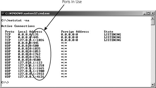
To see which ports are in use on a Windows, Linux, or UNIX system, you can use the netstat command locally on the machine. If you type netstat -na at the command prompt on Linux/UNIX or modern Windows machines, all ports sending data and listening for data will be displayed, as shown in Figure 2.7. The -na flags in the command mean show all ports, and list the network addresses in numerical form (i.e., don’t print out the full machine and service names). As we shall see in later chapters, learning what is listening on various ports is a useful technique in discovering an attacker’s presence on your system.
Figure 2.7 The netstat command shows ports in use.
![]() To understand how an attacker can subvert the functionality of the netstat program, refer to the Chapter 10 section titled “Additional Linux/UNIX User-Mode Rootkit Hiding Techniques.”
To understand how an attacker can subvert the functionality of the netstat program, refer to the Chapter 10 section titled “Additional Linux/UNIX User-Mode Rootkit Hiding Techniques.”
![]() To get more detail about what is listening on each given port on a machine, refer to the Chapter 6 section titled “Harden Your Systems.”
To get more detail about what is listening on each given port on a machine, refer to the Chapter 6 section titled “Harden Your Systems.”
TCP Control Bits, the Three-Way Handshake, and Sequence Numbers
The TCP control bits, also known as the TCP flags, are a particularly useful part of the TCP header. Some of these eight small fields (each is only one bit in length) describe what part of a session the TCP packet is associated with, such as session initiation, acknowledgment, or session tear down. Also, the control bits can signify if the packet requires special, urgent handling by the TCP Layer, or if a given connection is congested. A close-up view of the control bits is shown in Figure 2.8.
Figure 2.8 A close-up view of the TCP header reveals the TCP control bits.
Each control bit can be set independently, so a single TCP packet header could include one or more of the control bits set to a value of zero or one. Usually, only one or sometimes two control bits are set to one in a given packet. The original six individual control bits have the following meanings:
- URG. The Urgent pointer in the TCP header field is significant. There is important data in here that needs to be handled quickly.
- ACK. The Acknowledgment field is significant. This packet is used to acknowledge earlier packets.
- PSH. This is the Push function, used to flush data through the TCP Layer immediately rather than holding it waiting for more data.
- RST. The connection should be reset, due to error or other interruption.
- SYN. The system should synchronize sequence numbers. This control bit is used during session establishment.
- FIN. There is no more data from the sender. Therefore, the session should be torn down.
With the introduction of RFC 3168, two additional control bits were introduced, which are located just before the original six control bits, bringing the grand total of control bits to eight. These newer TCP flags are the following:
- CWR. Congestion Window Reduced, which indicates that, due to network congestion, the queue of outstanding packets to send has been lowered.
- ECE. Explicit Congestion Notification Echo, which indicates that the connection is experiencing congestion.
The importance of the TCP control bits becomes obvious when we analyze how sessions are initiated in TCP. All legitimate TCP connections are established using a three-way handshake, a fundamental tool used by TCP to get its job done. The three-way handshake, depicted in Figure 2.9, allows systems to open a communication session, exchanging a set of sequence numbers for packets to use throughout the session.
Figure 2.9 The TCP three-way handshake.
Suppose a machine called Alice has some data to send to a system named Bob. Perhaps Alice is running a Web browser and Bob is a Web server. Alice starts the three-way handshake to establish a TCP connection by sending a packet with the SYN control bit set and with the sequence number set to some initial value, known as the initial sequence number (which we’ll call ISNA because it comes from Alice and Alice starts with an A). This initial sequence number is assigned dynamically by Alice’s TCP Layer software, and will be unique for this connection. When later packets are sent on this connection, the sequence numbers are incremented for each data octet transmitted for this connection. Bob receives this TCP SYN packet from Alice. If the destination port in the packet is open on Bob, Bob performs the second part of the three-way handshake with Alice. Bob sends back a single packet with both the ACK and SYN control bits set. In this one response packet, Bob also fills out the Sequence Number and Acknowledgment Number fields. With this response, Bob essentially says, “Alice, I ACKnowledge your session establishment request and Initial Sequence Number A (plus one), and I will SYNchronize with you using this Initial Sequence Number B.” So, Bob sends a SYN-ACK packet with ISNB, as well as an acknowledgment of ISNA+1. Note that Bob increments ISNA in the acknowledgment by one to indicate the sequence number of the next octet that Bob is expecting from Alice. In a sense, one sequence number is used up in the three-way handshake itself, in each direction. On receiving Bob’s response, Alice will complete the three-way handshake by sending a packet with the ACK control bit set, and an acknowledgment to ISNB+1, again to indicate that Alice is expecting the next octet.
In this way, Alice and Bob have used the control bits to establish a TCP session. Both sides have agreed on a set of sequence numbers they will use in the communication. All packets going from Alice to Bob will have incrementally higher sequence numbers, with the number increasing by one for each octet of data going from Alice to Bob, starting at ISNA+1. Likewise all packets going from Bob back to Alice will have sequence numbers starting at ISNB+1 and going up for each octet of data.
With this careful exchange and agreement on sequence numbers, TCP can now make sure all packets in the session arrive in the proper order. If two packets get reversed in transmission (because, for example, a later packet took a shorter path than an earlier packet), the TCP Layer can discover the problem and resequence the packets before passing them to the application. Likewise, if a packet is lost during transmission, TCP can discover the problem by looking at the sequence and acknowledgment numbers and retransmit the missing packet. Therefore, the three-way handshake and the sequence numbers that result from it allow TCP to have reliable, sequenced transmissions.
Whereas the ACK and SYN control bits are heavily used to establish a session, the FIN control bit is used to tear down a session. Each side sends a packet with the FIN control bit set to indicate the session should be ended.
The RST control bit is used to stop connections and free up the sequence numbers in use. If a machine receives a packet that it is not expecting (such as a packet that includes the ACK bit set when no session has been established), it could respond with a packet that has the RST bit set. This is a machine’s way of saying, “If you think a session exists, tear it down, because I don’t know what you are talking about!”
The URG control bit means that the data stream includes some urgent data. If the URG control bit is set to one, the Urgent pointer field indicates where in the data stream the really urgent data is. TCP doesn’t specify how the urgent data should be handled by the application; it merely allows the application on one side of a connection to flag the urgent data for the other side of the connection. The PSH control bit means that the TCP Layer should flush the packet through the stack quickly, not queuing it up for later delivery. The CWR and ECE control bits are associated with managing congestion on a link, and are independent of the three-way handshake.
![]() To see how an attacker can violate the three-way handshake when scanning a target, refer to the Chapter 6 section titled “Types of Nmap Scans.”
To see how an attacker can violate the three-way handshake when scanning a target, refer to the Chapter 6 section titled “Types of Nmap Scans.”
Other Fields in the TCP Header
Beyond the TCP header fields we’ve already discussed, several other fields are included in the TCP header. These additional fields are as follows:
- Data Offset. This field describes where in the TCP packet the header ends and the data starts. It is equal to the length of the TCP header in 32-bit words.
- Reserved. This field is reserved for future use.
- Window. This field is used to control the number of outstanding octets that can be sent from one system to another on a given connection. It gives each side of the communication a way to control the flow of packets from the other side to make sure that all packets are received properly and acknowledged appropriately before new packets are sent.
- Checksum. This checksum is used to verify that the TCP packet (header and data) was not corrupted in its journey across the network.
- Urgent pointer. This field has a pointer into the data of the packet to indicate where urgent information is located.
- Options. This set of variable length fields can indicate additional information about the TCP processing capabilities of either side of the connection. For example, if a TCP Layer can handle only TCP packets of a given maximum size, the system can indicate this limitation in the TCP Options.
- Padding. This field includes enough bits set to zero to extend the length of the TCP header so that it ends on a 32-bit boundary. It’s just fluff included in the header to make sure everything lines up evenly.
User Datagram Protocol (UDP)
Although the protocol family name is referred to as TCP/IP, there are other members of this family besides TCP and IP. UDP is another Transport Layer protocol that can ride on top of IP. TCP and UDP are like cousins. TCP gets more attention, and is used in the family name, but UDP is still the basis of some very important applications. An application developer can choose to transmit data using either TCP or UDP, depending on what the application needs from a transport layer. A given packet and communication stream is usually either TCP or UDP, and cannot utilize both protocols simultaneously. Services that utilize UDP include many streaming audio and video applications, database query/response-type services, and typical Domain Name System (DNS) queries and responses. To understand why these services are based on UDP, let’s analyze UDP’s characteristics in more detail.
UDP is connectionless—the protocol doesn’t know or remember the state of a connection. It doesn’t have any concept of session initiation, acknowledgment, tear down, or anything else. Furthermore, UDP itself does not retransmit lost packets, nor does it put them in the proper order. So, if packet 1, packet 2, and packet 3 are sent out, the destination may receive packet 2, packet 1, and another copy of packet 1. Packet 3 is lost, and packet 1 was somehow transmitted twice. Back in school, during a class on computer protocols, my professor wrote on the lecture board: “UDP = Unreliable Damn Protocol.” Being the typical student, I dutifully wrote this in my notebook and returned to my crossword puzzle (or nap). After cramming for the final, that definition of UDP stuck in my brain. Years later, during a technical meeting at my job, I mentioned how entertaining I thought it was that folks had actually named a protocol the “Unreliable Damn Protocol.” A look of horror shot through the room, and I gradually sulked under the conference table.
However, my professor was right in one sense: UDP is inherently unreliable. It might lose packets or send them out of order. But sometimes unreliability is acceptable, particularly when it can buy you speed. Some applications are much more interested in getting packets across the network quickly, and don’t need super-high reliability. Such applications do not want the overhead of a three-way handshake, sequence numbers on every packet, acknowledgments, and so on. Instead, for some applications, simplicity and speed are the requirements.
What types of applications have these requirements? Often, applications that transmit data meant for the human eye or ear, like streaming audio or video, fit the bill. Although your eyes and ears will cover up (or fill in the blank) if a packet is dropped on occasion, you are much more likely to notice if all packets are slowed down by excessive processing. Additionally, some query-response applications use UDP, most notably database access and DNS. When looking up the IP address for a particular domain name, DNS sends out one packet with a query to look up a domain name (e.g., a UDP packet that says, “Please look up www.skoudisstuff.com”) and receives a single UDP packet in response (e.g., a packet that says, “The IP address for www.skoudisstuff.com is 10.21.41.3”). These applications do not want the overhead associated with establishing a connection using the three-way handshake for just sending a single packet and getting a single response.
The UDP header shown in Figure 2.10 illustrates the simplicity of UDP. Essentially, only a source and destination port are included, together with the message length and a checksum. No sequence numbers or control bits are required.
UDP has 16-bit port numbers, so there are 65,536 possible UDP ports (including UDP port zero, which is reserved). Just like TCP, data comes from one port on the originating system (the UDP source port), and is destined for an open port on the destination system (the UDP destination port). One of the most widely used UDP services, DNS, listens for DNS queries on UDP port 53. Other UDP-based services include the following:
- The Trivial File Transfer Protocol (TFTP), UDP port 69
- The Simple Network Management Protocol (SNMP), UDP port 161
- Real Player Data (Audio/Video), a range of UDP ports including 7070, although some clients can be configured to use only TCP ports if desired
Is UDP Less Secure Than TCP?
Without a three-way handshake, is UDP less secure than TCP? In other words, are applications running on UDP any more difficult to secure than TCP-based services? Well, it is considerably harder for network components (such as firewalls and routers) to understand and track what is happening in an application using UDP as opposed to TCP. In particular, TCP’s control bits and sequence numbers give tremendous hints to firewalls and routers so they can more easily control a connection. A network element knows when a TCP session is being established, because it can refer to the SYN control bit. Likewise, a router or firewall knows when a packet is being acknowledged or a session is being torn down, simply by consulting the control bits and sequence numbers.
With UDP’s lack of control bits and sequence numbers, it’s much more difficult to track where the end systems are in their communications. UDP packets coming in from the Internet could be responses for legitimate services, or they could be malicious scans. By simply looking at the UDP header, there is no way to tell if the packet is the start of communication or a response. Therefore, controlling UDP is more difficult than securely handling TCP. Later in this chapter, we discuss firewalls and analyze some of the options for handling UDP in a more secure manner by adding stateful inspection that remembers earlier UDP packets to make decisions about later packets.
![]() To understand how attackers conduct scans for open UDP ports, refer to the Chapter 6 section titled “Don’t Forget UDP!”
To understand how attackers conduct scans for open UDP ports, refer to the Chapter 6 section titled “Don’t Forget UDP!”
Internet Protocol (IP) and Internet Control Message Protocol (ICMP)
Once the TCP or UDP Layer generates a packet, it must be sent across the network. The Transport Layer (TCP or UDP) passes the packet to the Network Layer for end-to-end packet delivery. IP is the most commonly used Network Layer today, and is used for all traffic moving across the Internet. The current widely deployed version of IP is IPv4, which the vast majority of Internet traffic relies on today. A newer version, called IPv6, offers increased address lengths, among other options. We focus on IPv4, given its extreme popularity. Although many systems today have software capable of speaking IPv6, the protocol still is used only in concentrated pockets and not on a widespread basis.
On receiving information from the Transport Layer, the IP Layer generates a header, shown in Figure 2.11 for IPv4, which includes the source and destination IP addresses. The header is added to the front of the TCP packet to create a resulting IP packet, which will be used to carry the entire contents (IP header, TCP header, and application-level data) across the network.
IP: Drop That Acronym and Put Your Hands in the Air!
For some bizarre reason, lawyers like to use the acronym “IP” to designate Intellectual Property, ignoring its widespread use as an abbreviation for the Internet Protocol. I’ve been in several meetings where a lawyer has declared “But we have to consider the IP implications!” confusing me as I try to think my way through the protocol stack. I’m sorry, but us techies claimed IP first, and we won’t give it up. Tell all of your lawyer friends that they can’t have the term IP.
LANs and Routers
To understand how IP works, we need to spend some time understanding how networks are constructed. The purpose of IP is to carry packets end to end across a network. But what exactly is a network? Complete networks are typically made up of fundamental building blocks called LANs. A LAN is simply a bunch of computers connected together using a hub, switch, or wireless access point, with no routers separating the systems. As their name implies, LANs are typically geographically small, usually within a single building or a small campus.
LANs are connected together using routers. A router’s job is to move packets between the LANs, thereby creating a big network, as shown in Figure 2.12. One or more Network Layer protocols move data end to end across the network, from a given end user computer across the originating LAN, through a series of routers, across the terminating LAN to the ultimate destination. Also, some systems are directly connected to routers or each other using point-to-point links. The Internet itself is nothing but a giant collection of LANs and point-to-point links connected together using a whole bunch of routers.
Figure 2.12 A network is comprised of LANs and point-to-point links connected by routers.
IP Addresses
IP addresses identify a particular machine on the network, and are 32 bits in length for IPv4. Every system directly connected to the Internet has a unique IP address. Because it is difficult for us limited human beings to read and make sense of a block of 32 bits, IP addresses are usually written in so-called dotted-quad notation. Dotted-quad notation lists each of the four eight-bit bundles of the IP address as a decimal number between 0 and 255, resulting in an IP address of the form w.x.y.z, such as 10.21.41.3. Figure 2.13 shows an example IP address.
Figure 2.13 The same IP address in dotted-quad notation and binary.
Every IP packet contains a source IP address, identifying the system that is sending the packet, and a destination IP address, which identifies the destination system for the packet.
![]() For an analysis of how an attacker determines all IP addresses in use on a target network, refer to the Chapter 6 section titled “Network Mapping.”
For an analysis of how an attacker determines all IP addresses in use on a target network, refer to the Chapter 6 section titled “Network Mapping.”
Netmasks
Every IP address actually consists of two components: the network address and the host address on that particular network. The network address describes the particular LAN where traffic can be directed for delivery. The host address identifies the particular machine on the given LAN.
So how does a computer or router know which part of an IP address refers to the network, and which part refers to the host? It determines this information based on something called the netmask. The netmask defines which bits are in the network address (and all the rest of the bits in the IP address are in the host component of the address). The netmask is a binary number that has its bits set to 1 when a given bit in the IP address is part of the network address. The netmask has a bit of zero when a given bit in the IP address is part of the host address. Therefore, you can figure out what the network address is by simply combining the whole IP address with the netmask using the logical AND function, as shown in Figure 2.14. Like IP addresses, netmasks are also written in dotted-quad notation.
Figure 2.14 Calculating the network address using the IP address and netmask.
Sometimes netmasks are indicated using Classless Inter-Domain Routing (CIDR) notation, where the IP address is followed by a slash and then a number (e.g., 10.21.0.0/16). The number after the slash indicates the number of 1 bits in the netmask, or, in other words, the number of bits of the given IP address that are associated with the network component of that IP address. The remaining bits are associated with the host part of the IP address.
![]() To see how attackers play with netmasks to determine a network’s broadcast address in launching a packet flood attack, refer to the Chapter 9 section titled “Smurf Attacks.”
To see how attackers play with netmasks to determine a network’s broadcast address in launching a packet flood attack, refer to the Chapter 9 section titled “Smurf Attacks.”
Packet Fragmentation in IP
Various network transmission media have different performance characteristics. Some media perform much better when packets are longer, whereas others benefit from having shorter packet lengths. For example, bouncing an IP packet off of a satellite is very different from sending a packet down the glass fiber across your office. Given the latency associated with sending information to a satellite, longer packets are better for performance, and shorter packets give better performance across low-latency networks. To optimize packet lengths for various communications links, IP offers network elements (such as routers or firewalls) the ability to slice up packets into smaller pieces, an operation called fragmentation. An end system or network device can take large IP packets and break them down into smaller fragments for transmission across the network. Each fragment gets its own IP header and carries one piece of the puzzle that was the original unfragmented packet. The end system’s IP Layer is responsible for reassembling the fragments into the original packet before passing the data up to the Transport Layer.
The IP header offers a few fields to support this fragmentation operation. First, the Fragment Offset field tells a system where the contents of a given fragment should be included when the entire packet is reassembled. This offset refers to the number of eight-octet slots (that’s 64-bit chunks) in the data field of the original packet to place the given fragment. Furthermore, the IP Identification field is used to support fragment reassembly. The IP Identification field is set by the originating system to a unique value for each original unfragmented packet to help the destination system reassemble the packet if it does get broken into fragments. Additionally, two flags in the IP header, the Don’t Fragment bit and the More Fragments bit, specify information about fragmentation. The sending system can set the Don’t Fragment bit to indicate that a packet should not be fragmented as it travels across the network. Also, if a packet is fragmented, the More Fragments bit indicates whether more fragments of the original packet are still on the way. These two bits can have the following values:
- Flag Bit 1, the Don’t Fragment bit: 0 = may fragment, 1 = don’t fragment.
- Flag Bit 2, the More Fragments bit: 0 = last fragment, 1 = more fragments.
![]() To see how attackers carefully analyze the IP Identification field while launching a very stealthy form of scan, refer to the Chapter 6 section titled “Idle Scanning: An Even Better Way to Obscure the Source Address.”
To see how attackers carefully analyze the IP Identification field while launching a very stealthy form of scan, refer to the Chapter 6 section titled “Idle Scanning: An Even Better Way to Obscure the Source Address.”
![]() To see how an attacker uses packet fragmentation to avoid detection by IDSs and blocking by IPSs, refer to the Chapter 6 section titled “IDS and IPS Evasion at the Network Level.”
To see how an attacker uses packet fragmentation to avoid detection by IDSs and blocking by IPSs, refer to the Chapter 6 section titled “IDS and IPS Evasion at the Network Level.”
Other Components of the IP Header
Now that we understand the meaning of the IP address and fragmentation fields in the IP header, let’s look at the other fields that make up an IP packet. The IP header includes:
- Version. These four bits describe which version of IP is in use. IP version 4 is the one in widespread use all over the Internet. We’re starting to see a very long and slow transition to IPv6.
- Hlen. This field is the Internet Header Length, the total length of the IP header.
- Service Type. This field is associated with quality of service, indicating to network elements how sensitive the traffic might be to delays.
- Total Length. This item identifies the total length of the IP packet, including the IP header and its data.
- Identification. This field is used to support fragment reassembly, with each original packet getting a unique IP Identification value from the originating system.
- Flags. These bits include the Don’t Fragment bit, and the More Fragments bit, as previously described.
- Fragment Offset. This number indicates where this fragment fits into the overall packet.
- Time-to-Live. This field is used to indicate the maximum number of router-to-router hops the packet should take as it crosses the network.
- Protocol. This field describes the protocol that is being carried by this IP packet. It is often set to a value corresponding to TCP or UDP.
- Header Checksum. This information is used to make sure the header does not get corrupted. It is recalculated at each router hop.
- Source IP Address. This field indicates the network and host where the packet originates.
- Destination IP Address. This field indicates the network and host where the packet is going.
- Options. These variable length fields indicate extended information for the IP Layer. In particular, they are used in source routing, an operation described in more detail next.
- Padding. This catch-all field is used to round out the length of the IP header so that it lines up on a 32-bit boundary.
![]() To understand how attackers map a network using the TTL field, refer to the Chapter 6 section titled “Traceroute: What Are the Hops?”
To understand how attackers map a network using the TTL field, refer to the Chapter 6 section titled “Traceroute: What Are the Hops?”
![]() To understand how attackers determine packet filter firewall rule sets using the TTL field, refer to the Chapter 6 section titled “Determining Firewall Filter Rules with Firewalk.”
To understand how attackers determine packet filter firewall rule sets using the TTL field, refer to the Chapter 6 section titled “Determining Firewall Filter Rules with Firewalk.”
![]() To see how an attacker uses various fields in the TCP and IP header to set up hidden communications channels across the network, refer to the Chapter 11 section titled “More Covert Channels: Using the TCP and IP Headers to Carry Data with Covert_TCP and Nushu.”
To see how an attacker uses various fields in the TCP and IP header to set up hidden communications channels across the network, refer to the Chapter 11 section titled “More Covert Channels: Using the TCP and IP Headers to Carry Data with Covert_TCP and Nushu.”
ICMP
The book describes networking in terms even a child could understand, choosing to anthropomorphize the underlying packet structure. The ping packet is described as a duck, who, with other packets (more ducks), spends a certain period of time on the host machine (the wise-eyed boat). At the same time each day (I suspect this is scheduled under cron), the little packets (ducks) exit the host.
—An excerpt from a review of the children’s book The Story About Ping on Amazon.com by a reader from El Segundo
Another critical member of the TCP/IP family is ICMP. ICMP is kind of like the network plumber. Its job is to transmit command and control information between systems and network elements to foster the transmission of actual data and to report errors. One system can use ICMP to determine whether another system is alive by sending it a ping, which is an ICMP Echo message. If the pinged system is alive, it will respond by sending an ICMP Echo Reply message. A router can use ICMP to tell a source system that it does not have a route to the required destination (an ICMP Destination Unreachable message). One host can tell another system to slow down the number of packets it is sending with an ICMP Source Quench message. You get the idea: ICMP is used for systems to exchange information about how data is flowing (or not flowing) through the network.
ICMP uses the same header format as IP for source and destination IP addresses, packet fragmentation, and other functions. The protocol field of the IP header is loaded with a value corresponding to ICMP (the number 1 means ICMP). After the IP header, in the data component of the IP packet, ICMP adds a field known as the ICMP type. The format of the remainder of the ICMP packet depends on this ICMP type. There are numerous ICMP message types, with a handful of the most widely used listed in Table 2.1.
Other Network-Level Issues
Routing Packets
To move data end to end across a network, the packets must be carried from their source to their destination. Routing is the process of moving a packet from one network to another network, with the goal of advancing the packet toward its destination in a relatively efficient way. Routing is accomplished by—you guessed it—routers. Routers determine the path that a packet should take across the network, specifying from hop to hop which network segments the packets should bounce through as they travel across the network. Like Little Red Riding Hood trying to determine the best way to get to Grandma’s house, routing determines the path.
Most networks today use dynamic routing, where the routers themselves determine the path that packets will use. The routers chat among themselves using a variety of routing protocols to determine the best paths for packets to travel. Back to our Little Red Riding Hood analogy, with dynamic routing protocols, routers act like the trees in the forest outside of Grandma’s house calculating the best path and telling Little Red the proper way to go. A large number of routing protocols of various complexity have been devised, including the Routing Information Protocol (RIP), Open Shortest Path First (OSPF) protocol, and the Border Gateway Protocol (BGP).
Another routing option involves static routes. With a static route, all traffic with the same destination address is always sent the same direction, regardless of potential link damage or any capacity concerns. With static routes, Little Red Riding Hood is forced to go the same way to Grandma’s house always, even if the bridge is washed out on her path. Static routes are often used for routers where routing seldom changes, and, due to security issues, dynamic routes are not desirable. Static routers are often used in an organization’s Internet gateway, where they are hard-coded into the firewalls and routers making up the Internet connection point.
IP offers yet another routing option known as source routing. With source routing, the source machine generating the packet determines which route the packet will take as it traverses the network. Each individual IP packet contains a list of routers that the packet will travel through as it goes across the network. If the packet is little Red Riding Hood, with source routing, step-by-step directions to Grandma’s house are tattooed to Red’s forehead.
![]() For an analysis of an attack based on source routing, refer to the Chapter 8 section titled “IP Address Spoofing Flavor 3: Spoofing with Source Routing.”
For an analysis of an attack based on source routing, refer to the Chapter 8 section titled “IP Address Spoofing Flavor 3: Spoofing with Source Routing.”
Network Address Translation
Blocks of IP addresses are assigned to various organizations and ISPs. Years ago, not anticipating ever connecting to the Internet, some organizations picked network address numbers at random and started building their own internal IP networks using these random IP addresses. You would see network architects picking their favorite number (“Gee, I like the number 4!”) and building a whole network based around that number (giving everything an IP address of 4.x.y.z). These addresses are often referred to as illegal addresses because they are officially assigned to another organization. Unfortunately, if someone using illegal addresses wants to connect to the Internet, we could potentially have two networks on the Internet with the same IP addresses. This situation would seriously mess up routing, because the Internet routers would not know where to send traffic for these duplicate destination addresses.
Furthermore, with the rush to connect to the Internet, there just aren’t enough spare IP addresses available for everyone who wants one. Therefore, the IETF set aside some address numbers for creating private IP networks in RFC 1918. You can build your own IP network using these set-aside IP addresses such as 10.x.y.z, 172.16.y.z, or 192.168.y.z. Many organizations are creating networks using these set-aside addresses. If you try to send data to one of these addresses on the Internet, it will be dropped, because these set-asides are not unique. They are referred to as “unroutable” or “private” because no router on the Internet will know how to reach these nonunique addresses.
So how do we support Internet access from a network that is using either illegal addresses or the set-asides described in RFC 1918? The answer is to map these problematic addresses to valid IP addresses at a network gateway using a technique called Network Address Translation (NAT). To implement NAT, a gateway (which might be a router or firewall) sits between the network with the illegal or set-aside network and the Internet. As depicted in Figure 2.15, when each packet goes from the internal network to the Internet, this gateway alters the private source IP address of the internal network in the packet header, overwriting it with a unique, routable IP address. When responses come back, the gateway will receive these packets, and rewrite the destination IP addresses before forwarding them through to the internal network.
Figure 2.15 Network Address Translation overwrites the unroutable IP addresses from the internal network.
The gateway can map the addresses for NAT in a variety of ways, including the following:
- Mapping to single external IP address. For this type of NAT, every packet coming from the internal network is mapped to a single IP address. On the Internet, all traffic appears to be coming from the NAT device’s IP address. This very address-efficient technique is commonly used to connect a large network to the Internet when a limited number of IP addresses are available. To keep track of the different connections going to each outside system, the NAT device maintains state for each connection. Many NAT devices set a unique source port number in all outbound packets whose address has been translated, so that responses coming back to that port can be mapped back to the proper internal IP address and original internal port. Such port twiddling to implement NAT is sometimes called Port Address Translation (PAT).
- One-to-one mapping. The gateway could map each machine on the internal network to a unique valid IP address associated with each single machine.
Therefore, all traffic would appear to come from a group of IP addresses. This technique is often used to map user requests across the Internet to servers on a perimeter network, such as a Web server on a Demilitarized Zone (DMZ). - Dynamically allocated address. The gateway could multiplex a large number of unroutable IP addresses to a smaller number of valid IP addresses. This approach is less common than the other techniques.
To conserve IP addresses, NAT is very commonly utilized on the Internet today. However, does NAT improve security? It does help hide a network’s internal IP address usage, which an attacker could use to develop a network topology. However, by itself, NAT offers few security benefits. Although attackers cannot directly send packets to the private addresses on the internal network, they can still send packets to or even through the NAT gateway. The attacker might be able to take over the NAT device and then compromise the internal network. Or, without compromising the NAT device itself, the attacker could ride across the NAT, with the gateway mapping the addresses back and forth on behalf of the attacker. For this reason, NAT techniques must be combined with a secure firewall implementation if security is required.
Firewalls: Network Traffic Cops and Soccer Goalies
Firewalls are tools that control the flow of traffic going between networks. They sit at the border between networks, acting as a gateway that makes decisions about what kind of traffic should be allowed through and what should be denied. By looking at the services, addresses, data, and possibly even users associated with the traffic, firewalls determine whether connections should be transmitted through to the other network or dropped. With this capability, firewalls act rather like network traffic cops, as shown in Figure 2.16.
Figure 2.16 A firewall protects networks from each other.
If configured correctly, systems on one side of the firewall are protected from attackers on the other side of the firewall. Attackers can access the protected system only in ways allowed by the firewall. Organizations commonly use firewalls to protect their infrastructure from the big, bad Internet and from attacks across business partner connections. Additionally, internal network firewalls are proliferating, protecting sensitive internal networks (such as human resources and legal support) from other locations in the organization.
Another useful analogy for a firewall is a goalie in a soccer game. The goalie’s job is to prevent the opposing team from kicking the ball into the net. The soccer ball is rather like a packet. A firewall’s job is to prevent an attacker from sending unwarranted packets into a network. However, a goalie must allow the ball to be kicked out from the net, or else there won’t be much of a game. A firewall must allow some outgoing connections, so internal users can access the external network, while denying most incoming connections, except for specific services, as shown in Figure 2.17.
Figure 2.17 The goalie protects the internal network, while allowing the ball to be kicked out from the net.
The objective of an attacker is, therefore, to kick the ball past the goalie into the protected net. To understand our defenses, let’s look at the goalie’s capabilities by analyzing the firewall technologies in widespread use: traditional packet filters, stateful packet filters, and proxy-based firewalls. We’ll also look at a highly related technology, network-based Intrusion Prevention Systems (IPSs).
Traditional Packet Filters
Traditional packet filters can be implemented on a router or a firewall. As their name demonstrates, packet filters focus on individual packets, analyzing their header information and direction. A traditional packet-filtering device analyzes each packet going through it to make a decision on whether the packet should be transmitted or dropped. Traditional packet filters make this decision based on the following information:
- Source IP address. Does the packet appear to come from an IP address that should be allowed into the network? This information, gathered from the packet’s IP header, indicates the apparent source machine or network sending the packet.
- Destination IP address. Is the packet going to a server that should receive this type of traffic? This field, also from the IP header of the packet, indicates the intended destination machine or network of the packet.
- Source TCP/UDP port. What is the source port for the packet, and does it signify a specific application? This information is gleaned from the TCP or UDP header.
- Destination TCP/UDP port. What is the destination port? Because common services often use the well-known ports in that list maintained by the IANA, the destination port is used to allow some services while denying others. This information is also gathered from the packet’s TCP or UDP header.
- TCP control bits. Does the packet have the SYN bit set, meaning it is part of a connection initiation, or does it have the ACK bit set, implying it is part of an already-established connection? This information is very useful to a packet filter trying to decide whether the packets should be allowed or not. Of course, this data is not present in UDP packets, which have no concept of control bits.
- Protocol in use. Should this protocol be allowed into the network? The packet filter might allow TCP packets while denying UDP, or vice versa.
- Direction. Is the packet coming into the packet-filtering device, or leaving from it? The packet-filtering device can make filtering decisions based on this direction of packet flow.
- Interface. Did the packet come from a trusted network or an untrusted network? The packet-filtering device can transmit or drop packets based on the network interface on which they arrive.
Packet-filtering devices (whether routers or firewalls) are configured with a series of packet-filtering rules, with each rule specifying whether a given type of packet should be admitted or dropped. These rules are often called packet-filtering Access Control Lists (ACLs), particularly when they are implemented on routers. Each vendor’s product supporting packet filtering has its own syntax for creating these rules, with some products offering a custom language and others offering a GUI to define packet-filtering rules. Some common packet-filtering rules, using a vendorneutral, but understandable definition language, are shown in Table 2.2.
Table 2.2 Some Sample Packet Filter Rules
Let’s analyze these filter rules in more detail. It is important to understand that most packet-filtering devices apply their rules starting at the top of the list and moving down. A few products take a “best-fit” approach instead of this “first-fit” mentality, but let’s focus on first-fit because it is more common and more easily understood. The device takes the packet and starts scanning the rules. The first rule that matches the packet’s vital information is applied. The first rule in our list will allow packets from the inside network to the outside network to go to TCP port 80. This allows our internal users to send packets to external Web servers. The second rule allows outside systems to send TCP packets to the internal network to a high port number, as long as the ACK bit is set and the source port is 80. This rule is designed to allow responses from the external Web servers back into the internal network (remember that the browser client is dynamically assigned a high-number port by the TCP Layer). Finally, the last rule denies all traffic, making sure everything will be dropped except the traffic explicitly allowed by earlier rules. This deny-all statement at the end is crucial to make sure nothing slips through the cracks.
One major concern about traditional packet filters like this is their extremely limited view of what the traffic is actually doing. Notice the ACK rule in Table 2.2. This rule is a pretty big opening, allowing anyone on the external network to send TCP packets into the protected network as long as the ACK bit is set, the source port is 80, and the destination port is greater than 1023. Unfortunately, the packet-filtering device doesn’t have a lot of information on which to base its determination regarding whether that incoming packet is a response to a Web request or an attack. It can only look at each packet’s header and decide. A similar problem is found with UDP packets. Remember, UDP packets do not have control bits, so there is no indication of whether a packet is part of a session initiation (like a TCP packet with the SYN control bit set) or an acknowledgment (like a TCP packet with the ACK bit set). Because a traditional packet filter can only look at the packet headers to make its decisions, an attacker could pretty easily kick the ball past this goalie.
Despite this limitation, however, packet-filtering devices are in widespread use today, particularly at internal network routers and border routers connecting companies to the Internet. A great benefit of traditional packet filters is their speed. Because of their simplicity, a decision can be made rapidly about whether a packet should be sent.
![]() To see how an attacker conducts an ACK scan against a network, refer to the Chapter 6 section titled “Kicking the Ball Past The Goalie: TCP ACK Scans.”
To see how an attacker conducts an ACK scan against a network, refer to the Chapter 6 section titled “Kicking the Ball Past The Goalie: TCP ACK Scans.”
Stateful Packet Filters
So, traditional packet filters are limited because they can only look at a particular packet’s information to make a decision. How can we improve on this basic idea to create more powerful filters? Stateful packet filters deal with the problems of traditional packet filters by adding some more intelligence to the packet filter decision-making process. In addition to making decisions based on all the elements used by a traditional packet filter, stateful packet filters add memory to the process. A stateful packet filter can remember earlier packets that went through the device and make decisions about later packets based on this memory. That’s why they are called stateful—they remember packets.
This memory is implemented in a state table, which stores information about each active connection and other memorable packets. Unlike the packet filter rule we discussed earlier, which is static once it is defined by a network administrator, the state table is dynamic, updated in real time as packets traverse the device. This table remembers earlier packets so that the stateful packet filter can make decisions based on packet filter rules as well as the state table itself. An example state table is shown in Table 2.3.
Table 2.3 A Generic State Table from a Stateful Packet-Filtering Device
When a packet that is part of a session initiation (a TCP packet with the SYN control bit) is sent, the packet filter remembers it in its state table. When a new packet tries to go through the device, the packet filter consults its state table in addition to its rule set. If the rules allow a packet to be transmitted only if it is part of an earlier connection, the stateful packet-filtering device will transmit the packet if there is a suitable entry in its state table. Otherwise, the packet is dropped. So, if there was an earlier SYN packet, an ACK will be transmitted through the packet filter. Otherwise, the ACK will be dropped, because it is not part of a legitimate connection.
The state table remembers various packets for a set amount of time, usually ranging between 10 and 90 seconds, or even longer in some implementations. After that interval, if no further packets are associated with the entry in the state table, the entry is deleted, meaning no further packets are allowed for that connection.
Let’s consider our previous example of allowing responses to Web requests by letting in any TCP packet going to a high-numbered port if the ACK bit is set. An attacker could send packets through this filter simply by using a tool that generates packets with the ACK bit set to scan our entire protected network. A stateful packet filter, on the other hand, remembers the outgoing SYN packet for the original Web request. Then, it will only let an ACK packet into the network if it comes from a system that is reflected by a SYN entry in the state table. If an attacker tries to send ACK packets from addresses and ports for which there is no earlier SYN, the stateful packet filter will drop the packets.
In addition to remembering TCP control bits, a stateful packet filter can also remember UDP packets, and allow incoming UDP packets only if there was a previous outgoing packet. Additionally, stateful packet filtering helps to secure more complex services, like FTP, which requires two connections to transfer a file: an FTP Control Connection (across which commands to get directory listings and transfer files are sent) and an FTP Data Connection (where the file listings and files themselves are sent). Stateful packet filters can be configured to allow FTP Data Connections only when an FTP Control Connection is established, thus policing the protocol more carefully than a traditional (nonstateful) packet filter.
With these techniques, stateful packet filters have significantly better security abilities than traditional packet filters. Because they have to consult their state tables, stateful packet filters are usually slightly slower than traditional packet filters. However, this change in performance is usually negligible given the significantly improved security. Furthermore, with custom Application-Specific Integrated Circuit (ASIC) chips, stateful filtering can still operate quite quickly. Given these great benefits, many firewall solutions today are based on stateful packet-filtering technologies.
Proxy-Based Firewalls
Packet-filtering devices, whether traditional or stateful, focus on packets, looking at the information provided in the TCP and IP Layers. Proxies represent an entirely different approach to controlling the flow of information through a firewall. Rather than obsessing over packets, proxies focus on the application level, analyzing the application information passing through them to make decisions about transmitting or dropping.
To understand proxy firewalls and application-level control, consider this analogy: My mom called the other night to speak with me. My wife answered the phone. I was tremendously tired, having stayed up late the night before writing about protocol layering. As much as I love my mother, I moaned to my wife, “I’m way too tired to speak with her now. Tell her to go away!” My wife, who had answered the phone, said to my mother, “Ed’s very tired right now. Can he please call you back tomorrow?” Likewise, when a telemarketer called me looking to sell widgets, my wife didn’t even tell me. She instead told the caller that he had the wrong number.
In both of these situations, my wife acted as a proxy for me. I interacted with my wife, and my wife interacted with the other party. She was able to make decisions about what to say based on the application-level context of what was happening. She cleaned up the protocol I used to speak with my mom, and she denied altogether an interaction from the telemarketer because she didn’t want that application to contact me.
Proxy firewalls work the same way. As pictured in Figure 2.18, a client interacts with the proxy, and the proxy interacts with a server on behalf of the client. All connections for other applications, clients, or servers can be dropped.
Figure 2.18 The proxy-based firewall implements application-level controls.
A proxy can authenticate users, as it operates at the application level and can display a user ID and password prompt or other authentication request. Web, telnet, and FTP proxies often include the ability to authenticate users before passing the connection through the proxy.
A proxy-based firewall is not subject to the ACK attack scan issue we saw with traditional packet filters, because the ACK is not part of a meaningful application request. It will be dropped by the proxy. Furthermore, given its focus on the application level, a proxy-based firewall can comb through the application-level protocol to ensure that all exchanges strictly conform to the protocol message set. For example, a Web proxy can make sure that all messages are properly formatted HTTP, rather than just checking to make sure that they go to destination TCP port 80. Furthermore, the proxy can allow or deny application-level functions. So, for FTP, the proxy could allow FTP GETs, so a user could bring files into the network, while denying FTP PUTs, stopping users from transferring files out using FTP.
Also, a proxy can help optimize performance by caching frequently accessed information, rather than sending new requests for the same old data to servers. Web proxies frequently include this caching capability. It is important to note that some vendors sell proxies that are focused on these performance optimization measures only, without providing real security. These proxies are useful for caching and other bandwidth optimizations, but only a tool designed for securely proxying applications should be used as a firewall.
Although particular vendor implementations vary greatly, generally speaking, proxy-based firewalls tend to be somewhat slower than packet filter firewalls, because of their focus on the application level and detailed combing of the protocol. Proxies have much more control over the data flow, but that control costs CPU cycles and memory. Therefore, to handle the same amount of traffic, proxy-based firewalls usually require a higher performance processor.
![]() To see how an attacker can send a command-line session through a stateful packet filter or even a proxy-based firewall by making it look like Web traffic, refer to the Chapter 11 section titled “Reverse WWW Shell: Covert Channels Using HTTP.”
To see how an attacker can send a command-line session through a stateful packet filter or even a proxy-based firewall by making it look like Web traffic, refer to the Chapter 11 section titled “Reverse WWW Shell: Covert Channels Using HTTP.”
Not Exactly Firewalls: Network-Based Intrusion Prevention Systems (IPSs)
Although not exactly firewalls, network-based IPSs share some important characteristics. These tools monitor traffic going across a network and match it against a set of signatures that identify various kinds of attacks, such as the buffer overflows and related exploits we discuss in Chapter 7, Phase 3: Gaining Access Using Application and Operating System Attacks. Some IPSs even maintain a sense of normal traffic behavior and look for deviations from normal patterns consistent with a scan or propagating malicious code such as worms. If some network traffic matches an attack signature, the network-based IPS can block the communication before it has a chance to hit target systems. Those network-based IPS tools that monitor traffic patterns can likewise throttle eruptions of traffic consistent with a scan or a worm to slow down or even stop attacks.
Although both kinds of tools have the ability to filter, network-based IPS tools are different from firewalls. Firewalls are typically configured to allow only certain kinds of services or ports through the device, blocking all other traffic. However, the firewall doesn’t have signatures for specific kinds of attack, nor does it typically have knowledge of normal traffic patterns. An IPS, on the other hand, usually allows through all traffic, except those packets that are associated with known attacks that match the IPS signatures. Firewall-type rules can be defined on some network-based IPS tools as well, but network-based IPS tools typically just focus on specific attack signatures and behavior, pulling out the evil stuff they detect.
Which Technology Is Better for Firewalling?
Should you use stateful packet filtering or proxy-based firewalls to protect your network? That depends on the specific services you need to support through the firewall and the performance characteristics you require. If implemented with properly optimized rule sets, either technology can support the security needs of most organizations.
I like to see networks that employ an Internet gateway built with packet-filtering systems and proxy-based systems in a layered fashion. For example, an external stateful packet filter might shield your DMZ, whereas a proxy-based firewall sits just inside that system to protect your internal network, as shown in Figure 2.19. That way, you get the best of both worlds. Of course, there are countless different architecture options of varying complexity for creating an Internet gateway, each optimizing for a different need.
Figure 2.19 A simple example architecture employing both packet filtering and proxy technologies.
Don’t Forget About the Data Link and Physical Layers!
Let’s continue our journey down the protocol stack by talking about the common technologies used to construct the Data Link and Physical Layers underlying most TCP/IP stacks. Officially, these Data Link and Physical Layer protocols are not part of the TCP/IP family. Still, attackers frequently take advantage of these underlying technologies, so we need to understand them.
What makes up the Data Link and Physical Layers? The Data Link Layer consists of the software drivers for your network interface card, plus some firmware on the card itself. The Physical Layer is the hardware of your network interface card, plus the actual physical media (the wires, fiber, or radio frequency spectrum) making up the network.
The Data Link and Physical Layers are used to construct LANs, point-to-point connections, and Wide Area Network (WAN) links. The IP Layer generates an IP packet, and passes it down to the Data Link and Physical Layers, which transmit the data across a single link (the LAN, point-to-point connection, or WAN) on behalf of the IP Layer. The Data Link and Physical Layers move packets from one system across one hop to another system or a router. Additionally, these layers are used to move packets from one router to another router. By far, the two most popular LAN technologies today are Ethernet for wireline communication and the 802.11 family of protocols for wireless communication.
Ethernet: The King of Wireline Connectivity
Numerous options are available today for implementing the Data Link and Physical Layers for wireline transmissions, each based on a different LAN technology. Wireline LAN technologies include Fiber Distributed Data Interface (FDDI), token ring, Ethernet, and numerous others. Among this plethora of options, one stands out as the most widely used wireline LAN technology of all: Ethernet. Call it the king of connectivity. The vast majority of corporate networks (and numerous home networks) are based on Ethernet. Because Ethernet is so dominant and attackers have devised several ingenious methods for attacking it, we analyze it in more detail.
Ethernet is not exactly a monolith, however. Several different versions of Ethernet have evolved, each with different speeds: 10 megabits per second (the original version of Ethernet), 100 megabits per second, Gigabit Ethernet, and beyond.
Each type of Ethernet includes the concept of a Media Access Control (MAC) address. MAC is a subset of the Data Link Layer associated with controlling access to the physical network wire. MAC is not limited to just Ethernet, as it is used in various LAN technologies, including the wireless technologies we discuss later in this chapter. But in the Ethernet realm, each and every Ethernet card has a unique MAC address, which is 48 bits long. To ensure these MAC addresses are globally unique, each Ethernet card manufacturer has received a specific allocation of addresses to use, wiring (or hard-coding) a unique address into every Ethernet card manufactured. Because the MAC address is unique, this number can be used to unambiguously identify every network interface.
ARP ARP ARP!!
When a machine has data to send to another system across a LAN, it has to figure out what physical node should receive the data. Remember, the data that was pushed down the TCP/IP stack includes a destination IP address in the header. However, we can’t just blurt out the data to an IP address somewhere on the LAN, because the IP Layer isn’t sitting listening to the wire. We have to send the data to a physical network interface implementing the Data Link and Physical Layers. So, how do we identify the appropriate destination Data Link and Physical Layers? The network interface card can be identified using the MAC address. That’s great, but how do we know which MAC address to send the packet to, given that the TCP/IP stack has just passed us the destination IP address?
To map a particular IP address to a given MAC address so that packets can be transmitted across a LAN, systems use the Address Resolution Protocol (ARP), illustrated in Figure 2.20. ARP can be applied to LAN technologies besides Ethernet, but RFC 826 defines ARP and how it should be used for Ethernet.
Figure 2.20 The Address Resolution Protocol.
When one system has a packet to send across the LAN, it sends out an ARP query. The ARP query is typically broadcast to all systems on the LAN, and asks, “Who has the MAC address associated with IP address w.x.y.z?” where w.x.y.z is the destination IP address for the packet to be delivered. Every system on the LAN receives the broadcast, and the system configured with that requested IP address sends an ARP response. The response essentially says, “I’ve got that IP address, and my MAC address is AA.BB.CC.DD.EE.FF.” The sending system then transmits the packet to this destination MAC address and stores the information mapping IP address to MAC address in its ARP cache. The ARP cache is a table containing IP-to-MAC address mappings, and is used to minimize future ARP traffic. The ARP cache maps Layer 3 (the IP address) to Layer 2 (the MAC address), and is stored on each system communicating on the LAN. When another packet needs to go to the same destination again on the LAN, the sending system will look up the IP address to determine the MAC address from its ARP cache, rather than sending another ARP query. ARP cache entries have a lifetime that depends on the operating system type, but typically last between several minutes and half an hour. After this lifetime expires, ARP is used to refresh the ARP cache.
It is important to note that ARP, which is a Data Link Layer concept, applies only across LANs, and is not transmitted by routers from one LAN to another. Therefore, ARP queries and responses are not transmitted across the Internet or anywhere beyond a given LAN.
![]() To see how an attacker can forge ARP messages to hijack a session, refer to the Chapter 8 section titled “Session Hijacking.”
To see how an attacker can forge ARP messages to hijack a session, refer to the Chapter 8 section titled “Session Hijacking.”
Hubs and Switches
Ethernet LANs are constructed using hubs or switches, devices that have various physical interfaces for plugging in Ethernet cables. Each system on a LAN has an Ethernet cable plugged into one of these physical interfaces on a switch or hub. The switch or hub has an internal backplane where all data is transmitted between the appropriate physical interfaces. Although hubs and switches share similar physical appearances (a box with a bunch of plugs), they have very different ways of handling data, as shown in Figure 2.21.
Figure 2.21 Comparing broadcast Ethernet to switched Ethernet.
A hub is a very simple device. It simply broadcasts information received on one physical interface to all other physical connections on the box. A hub is therefore a broadcast device, acting like a repeater. When one system wants to send data to another system on a LAN implemented with a hub, all other systems on that LAN can see the data.
![]() To understand how an attacker can easily capture data sent through a hub, refer to the Chapter 8 section titled “Sniffing Through a Hub: Passive Sniffing.”
To understand how an attacker can easily capture data sent through a hub, refer to the Chapter 8 section titled “Sniffing Through a Hub: Passive Sniffing.”
A switch, on the other hand, has additional intelligence so that it doesn’t have to broadcast data to all physical interfaces. A switch listens to the traffic flowing through it and associates particular source MAC addresses from that traffic with each physical plug on the device. The switch has memory where it stores the mapping of MAC address to physical port (that is, Layer 2 to Layer 1). Some vendors refer to this table as the Content Addressable Memory (CAM) table. When packets are transmitted through a switch, the switch will send the data to the single physical interface associated with the destination MAC address, as shown in Figure 2.22. Therefore, data is physically isolated to the plug and wire connection of the destination system, and is not sent to every machine on the LAN. The switch auto-discovers which machines are connected to which physical interfaces by listening to the MAC addresses of traffic of the LAN. Alternatively, a network administrator could configure the switch to hard-code the MAC address associated with each physical interface right into the switch.
Figure 2.22 A switch helps isolate data.
Attacking a LAN implemented with a hub can be quite trivial. For switches, which are more intelligent devices, attackers have created some very interesting attacks against these more sophisticated LAN components. Today, most networks are made up of switches, a much more popular technology given their better performance characteristics and (very slight) improvement in security.
![]() To understand how an attacker can gather data from a switched LAN, refer to the Chapter 8 section titled “Active Sniffing: Sniffing Through a Switch and Other Cool Goodies.”
To understand how an attacker can gather data from a switched LAN, refer to the Chapter 8 section titled “Active Sniffing: Sniffing Through a Switch and Other Cool Goodies.”
802.11: The King of Wireless Connectivity
Although Ethernet still remains popular, the world is also awash in wireless. From cell phones to wireless LANs (WLANs), the convenience and mobility brought about by wireless technologies has fostered their rapid deployment and widespread use. The explosive growth of WLAN technologies, with new access points popping up all over the place, is particularly good news for the bad guys. Unsecured wireless access is often one of the easiest ways to break into an otherwise well-fortified network. What’s more, using a “borrowed” access point left open by a neighbor, Internet café, or fast-food restaurant, attackers can achieve a level of untraceability that used to require a lot of work in setting up relay points to bounce through compromised systems in the wireline world.
From a wireless networking perspective, one of the most popular technologies is the 802.11 family of protocols, defined by the Institute of Electrical and Electronics Engineers (IEEE). This set of protocols was designed as a seamless replacement of the Data Link and Physical Layers of Ethernet. This design is very helpful for the good guys, because new applications can be carried across wireless without redevelopment effort. But it’s even better news for the attackers for three reasons. First, all of the attacks designed to work in IP networks can be carried right across most WLANs without any changes whatsoever. All of the major sniffers and ARP cache poisoning attacks we discuss in Chapter 8, Phase 3: Gaining Access Using Network Attacks, work very well against WLANs based on 802.11 technology. Likewise, the buffer overflows and other attacks discussed throughout the book can be carried without a glitch across wireless networks.
Second, attackers now have great new Physical Link and Data Link properties to attack. They can gain “physical” access to a network without having to jack into a plug in the wall. Wireless signal bleed is a very beautiful thing for the bad guys, who can sometimes join WLANs from hundreds of yards or more away! From a data link perspective, a whole new message set is available to manipulate in attempting to gain access to WLANs. We’ll look at these wireless messages later in this section.
Finally, being able to replace just the Data Link and Physical Layers of existing network protocol stacks with wireless devices has made an already very hackable world even more hackable. As organizations and individuals race to deploy wireless without much regard for its security implications, the bad guys now have a vast number of systems to target.
Given that WLANs are designed to be easily swappable for wireline Ethernet networks, some people refer to 802.11 as wireless Ethernet, a phrase I’m not too fond of, given its technical inaccuracy. Still, you do hear it, and it does sum up the goals of wireless connectivity. Another popular term is Wi-Fi, which refers to an industry alliance of vendors and other interested parties that test interoperability. Although the term Wi-Fi refers to this alliance, many people use it as a name for any 802.11 WLAN technologies.
One important similarity between Ethernet and the 802.11 family is their reliance on MAC addresses, the ARP protocol, and ARP caches. Just as systems on wireline Ethernet LANs use ARP to create a mapping of IP addresses to MAC addresses, so too do systems communicating on a WLAN. Wireless MAC addresses are also 48 bits in length.
The 802.11 family includes numerous members, but some of the most popular and important protocols within this family include the following:
- 802.11. This protocol, originally defined in 1997, was the first standard in the family, describing the MAC layer and frequency-hopping techniques, providing a paltry maximum bandwidth of 2 Mbps. Given that relatively slow speed, this particular protocol didn’t gain widespread use. Today, this term is applied to the whole family of 802.11 protocols, instead of just that one ancient standard from 1997.
- 802.11a. This was the second physical layer standard for the 802.11 family, defined in 1999, with a maximum bandwidth of 54 Mbps. Released about the same time as 802.11b, solutions using this protocol were more expensive than the 802.11b, giving them lower popularity despite their higher bandwidth.
- 802.11b. This third physical layer defined in the family, standardized back in 1999, became the first widely deployed member of the 802.11 family given its low cost and acceptable maximum bandwidth of 11 Mbps, comparable to traditional wireline Ethernet.
- 802.11g. This standard, finalized in 2003, has gained widespread acceptance because of its higher bandwidth (maxing out at 54 Mbps) and low cost, combining the best features of 802.11a and 802.11b.
- 802.11i. This standard, ratified in 2004, offers improvements to the security of 802.11, including stronger encryption (based on the Advanced Encryption Standard, better known as AES) and better key exchange using a protocol called the Temporal Key Integrity Protocol (TKIP).
WLANs implemented using 802.11 technologies can operate in two modes: independent (sometimes called peer-to-peer) mode, where each system is an equal partner on the LAN, and infrastructure (sometimes called access-point) mode, where one system is in charge. In independent mode, a group of wireless computers can create an ad-hoc network and start exchanging data directly with each other. In infrastructure mode, an administrator deploys an access point, a central point for the WLAN. All computers using that WLAN then send all data through the access point. The access point itself might have a connection to a wireline network, acting as an on-ramp for accessing the Internet itself.
Regardless of whether the network is independent or infrastructure in nature, all 802.11 wireless communications must be controlled with various management frames, special packets sent by the devices communicating wirelessly to coordinate communication. The wireless management frame types supported by 802.11 include the following:
- Beacon. In infrastructure networks, access points use these frames to announce the existence of a WLAN, sending them at regular intervals, typically approximately every 100 ms by default.
- Probe request. Wireless devices can use these frames to find existing 802.11 networks, requesting which access points are nearby.
- Probe response. An access point can respond to a probe request with this type of frame, indicating that it is present.
- Association request. This frame is used to join a WLAN.
- Association response. An access point uses this frame to grant access to the WLAN.
- Disassociation. This frame is used to tear down a relationship with a WLAN.
These management frames are highly useful to attackers in a variety of ways in locating and attempting to undermine a wireless access point.
![]() To see how an attacker uses probe request frames to find wireless LANs, refer to the Chapter 6 section titled “War Driving Method 1: Active Scanning—Sending Probe Packets with NetStumbler.”
To see how an attacker uses probe request frames to find wireless LANs, refer to the Chapter 6 section titled “War Driving Method 1: Active Scanning—Sending Probe Packets with NetStumbler.”
![]() To see how an attacker listens for beacon frames to find WLANs, refer to the Chapter 6 section titled “War Driving Method 2: Listening for Beacons and Other Traffic with Wellenreiter.”
To see how an attacker listens for beacon frames to find WLANs, refer to the Chapter 6 section titled “War Driving Method 2: Listening for Beacons and Other Traffic with Wellenreiter.”
Security Solutions for the Internet
Unfortunately, the original designs of TCP/IP and related technologies did not include security capabilities. Traditional TCP/IP stacks offer no real protections for ensuring the confidentiality, integrity, authentication, and availability of data as it is transmitted through the network. Although these base technologies ignore security, a few significant and somewhat successful efforts have been launched to slap security on top of or retrofit it into the existing Internet. Let’s explore several efforts to add security to TCP/IP-based networks, including application-level security, the Secure Sockets Layer (SSL), and IPSec.
Application-Level Security
Through much of its history, TCP/IP did not include security functionality, instead relying on the applications using TCP/IP to secure the data themselves. If the application required confidentiality, the application developers had to build encryption capabilities into the application level. For authentication, the application developers sometimes used digital signatures to verify who sent the data. When an application required checks of the integrity of data, it had to include a cryptographically strong hash. The application would secure the data using these techniques before passing it to the TCP/IP stack for transmission.
Numerous applications were created that have built-in application-level security, including financial applications, databases, medical history systems, and so on. Additionally, a large number of tools have been developed that protect data at the application level, but are useful for a variety of applications. Table 2.4 contains a variety of these application-level security tools widely used for various TCP/IP-based applications.
Table 2.4 Some Widely Used Application-Layer Security Tools
The Secure Sockets Layer (SSL) and Transport Layer Security (TLS)
Another option for providing security services to TCP/IP applications involves implementing security at a layer just above TCP/IP, known as the Sockets Layer. An application can include its own implementation of a Sockets Layer that has security capabilities, which sits between higher level application functions and the TCP/IP stack, as illustrated in Figure 2.23. Originally published by Netscape, SSL is a specification for implementing just this kind of security at the Sockets Layer. In 1999, the IETF released RFC 2246, which specifies the successor to SSL, known as Transport Layer Security (TLS). TLS represents a very small change to SSL, including tweaks to its message format and various cryptographic options. Because of the vast popularity of the original SSL and the extremely close relationship of SSL and TLS, most people still use the term SSL when referring to either SSL or TLS. In following this popular parlance, we use the term SSL throughout this book, but keep in mind that all of our discussions apply to both SSL and TLS.
Figure 2.23 How SSL fits in: SSL is included in the application program.
SSL and TLS allow applications to have authenticated, encrypted communications across a network. Both communicating sides of the application requiring security must include an implementation of SSL, which encrypts all data to be transported and sends the information to the TCP/IP stack for delivery. SSL includes a variety of encryption algorithms to secure data as it is transported. SSL relies on digital certificates to authenticate systems and distribute encryption keys. These digital certificates act like cryptographic identification cards, which can be used to verify another party’s identity. A certificate contains the public key of a given machine, which has been digitally signed by a certificate authority the other side needs to be configured to trust. SSL can provide one-way authentication of a server to a client (so that you can cryptographically verify you are dealing with a given e-commerce merchant, for example). Additionally, SSL can support mutual authentication of both the client and the server, provided that both sides have recognized digital certificates.
You probably use SSL quite often, perhaps without realizing it. When you surf to a secured Web site, and the key or lock in the lower corner of your browser appears, your browser has established an SSL connection with the site and verified its certificate. When you use HTTPS, you are actually running the HTTP protocol over SSL, which of course, is being carried by TCP/IP (pardon the alphabet soup of acronyms!).
To establish an SSL session between two systems, SSL defines a carefully orchestrated handshake so the two machines can agree on various encryption algorithms and settings, as well as exchange keys, as illustrated in Figure 2.24. The systems first complete the TCP three-way handshake, with its SYN, SYNACK, and ACK messages to exchange TCP sequence numbers. Next, the client sends an SSL CLIENT_HELLO message that specifies the particular cryptographic algorithms it can support, compression algorithms it wants to use, an SSL session ID number, and the highest SSL or TLS protocol version it can handle. This message also includes some random data that will be used in the session key generation process later. The server responds with, as you might guess, a SERVER_HELLO message, which includes the server’s choice of SSL or TLS version, the particular encryption algorithms to use, and chosen compression methods, all sent with that same SSL session ID number. This message also includes some randomly generated data for use in the session key generation process later.
Figure 2.24 Establishing an SSL session.

The server follows up with some pretty important data, the CERTIFICATE message, which includes the server’s digital certificate, that crucial data structure that holds the server’s public encryption key digitally signed by a certificate authority. This server public key in the certificate corresponds to a private key stored on the server. No one should know the private key except the server itself (and, of course, its human administrators). In this CERTIFICATE message, the server can also optionally send a chain of certificates of various certificate authorities that have signed the server’s own certificate or each other’s certificates. The server completes its part of the communication with a SERVER_DONE message.
Next, if the client has its own digital certificate, it can submit this to the server. The vast majority of SSL deployments today rely on server-side certificates only, so this step is often skipped. Regardless of whether client certificates are used or not, the next step involves a CERTIFICATE_VERIFY message, indicating that the client has checked out the server’s certificate and has decided to trust it; that is, the server certificate was signed by a certificate authority the client was configured to trust, or the client walked the chain of certificates provided by the server until it reached a certificate authority that was trusted. Web browsers, by default, are configured to trust several dozen certificate authorities from around the world. If the client software itself cannot verify the certificate, it might even prompt the user, asking whether the given certificate should be trusted. The client then issues a CHANGE_CIPHER_SPEC message to indicate that it is ready to start communicating in an encrypted fashion. The client’s final unencrypted message says that it is FINISHED, with a hash of all of the data sent in the communication so far to make sure that no one snuck in an evil message during the handshake itself. The server then issues its own CHANGE_CIPHER_SPEC and FINISHED messages to complete the handshake.
Now, we get to the payoff—using random data created by the client and server exchanged during the handshake, the client formulates a session key. The client encrypts the session key with the server’s public key that it retrieved from the server’s certificate. The encrypted session key is sent to the server. The server then uses its private key, which, remember, it keeps very secret, to decrypt the message from the client. Because only the server knows the server’s private key, only the server can decrypt this message to determine the session key. The session key, then, known only to the client and server, is used to encrypt all data for the SSL session going forward. In this way, SSL uses the server’s public and private key pair to exchange a session key that is used to encrypt all of the traffic.
You might be wondering why the client doesn’t just encrypt all of the data for the session using the server’s public key from the server certificate. Keep in mind that public key crypto algorithms have much lower performance than shared-key systems (often called symmetric key cryptosystems). Thus, SSL relies on public key algorithms to exchange a symmetric key, and then encrypts all of the data using the symmetric key on both sides. Public key cryptography is used here to bootstrap symmetric cryptography by exchanging a symmetric key.
There is one major concern associated with this SSL exchange. Did you spot it? It all depends on how much the client can trust that server certificate. If the server certificate is bogus but the client still accepts it, all of this handshaking is for naught. With a bogus certificate trusted by the client, the client will be encrypting information and sending it to someone evil, thinking that it is sending the data to someone good. In other words, the trust placed in the server certificate is paramount. If attackers can trick a legitimate certificate authority that the clients trust into signing their certificates, SSL will be undermined. There is some historical precedent here, with the certificate authority VeriSign issuing two certificates in 2002 to people claiming to be from Microsoft. These certificates weren’t for SSL, though. Instead, they were code-signing certificates, which are used by browsers to verify the author of software before running it. That’s pretty scary; someone managed to get certificates that they could use to impersonate Microsoft itself! These certificates were rapidly revoked, and a new version of Internet Explorer was released that automatically refused to accept those two certificates. Alternatively, instead of fooling a certificate authority, if the attacker can fool the certificate-checking software on the browser, SSL again fails to provide any real security. Every year or two, someone finds a browser flaw that can be exploited in this way, forcing vendors to release patches to their browser logic and users to upgrade. Finally, and of most concern, in most SSL implementations, the user gets a shot at saying whether he or she wants to trust a certificate. This user request is often the weakest link in the SSL process, giving the attacker an opportunity to dupe unsuspecting victims into trusting evil certificates.
![]() To see how an attacker can undermine SSL (as well as SSH) by tricking a user into accepting evil certificates and public keys, check out the Chapter 8 section titled “Sniffing HTTPS and SSH.”
To see how an attacker can undermine SSL (as well as SSH) by tricking a user into accepting evil certificates and public keys, check out the Chapter 8 section titled “Sniffing HTTPS and SSH.”
SSL is most often associated with Web browsing and HTTP, and indeed that is its biggest use today. However, other applications can use SSL, such as telnet, FTP, e-mail transfer, or anything else. Unfortunately, an application developer must typically modify both the client and the server of the applications to include SSL functionality. Alternatively, some products provide an SSL tunnel between two systems, carrying all traffic from various applications encrypted using SSL. A separate application is installed on both sides that authenticates and encrypts all data between the two communicating machines using SSL. These products are sometimes referred to as SSL Virtual Private Networks (VPNs). I typically avoid the phrase “SSL VPNs” myself. VPNs have historically been a construct of the network layer, as we’ll discuss next, not something at the Sockets Layer. Still, these products can be used to encrypt data with SSL for a variety of applications.
![]() To understand how an attacker can manipulate a Web application even though SSL is in use, refer to the Chapter 7 section titled “Web Application Attacks.”
To understand how an attacker can manipulate a Web application even though SSL is in use, refer to the Chapter 7 section titled “Web Application Attacks.”
Security at the IP Level: IPSec
Wouldn’t it be great if we could have secure communications without having to build security into our applications or integrate the applications with SSL? What if we could have support for security built right into our TCP/IP stack, so that any application using IP would be able to communicate securely, without any modifications to the application or a separate SSL tunneling application installed? The IETF tried to answer these questions in the mid-1990s by defining how security could be added to IP. The resulting specification is known as IP Security, or IPSec for short, and can be used to create VPNs.
IPSec functions at the IP Layer, offering authentication of the data source, confidentiality, data integrity, and protection against replays. Any two systems with compatible versions of IPSec can communicate securely over the network, such as my computer and your server, or my server and your firewall, or your firewall and my router. Of course, to pull this off, the two communicating systems must have some method for exchanging encryption keys, a difficult but not insurmountable issue we discuss in more detail shortly.
Because IPSec is offered at the IP Layer, any higher layer protocol, such as TCP, UDP, or anything else, can take advantage of IPSec. More important, any application riding on top of that higher layer protocol will benefit from the security capabilities of IPSec. IPSec has been retrofitted into IPv4, the IP that you and I use every day on the Internet. IPSec is also built into IPv6.
IPSec is really made up of two protocols, the Authentication Header (AH) and the Encapsulating Security Payload (ESP), each offering its own security capabilities. It should be noted that AH and ESP can be used independently or together in the same packet.
The IPSec Authentication Header
The AH provides authentication of the data source, data integrity, and, optionally, protection against replays. In essence, AH provides digital signatures for IP packets so that attackers cannot send packets impersonating another machine, or alter data as it moves across the network. Using AH, I can verify where a packet came from and ensure that it was not altered in transit. Figure 2.25 shows how AH fits into an IP packet (using IPv4). In the example shown in Figure 2.25, AH is just sandwiched in after the IPv4 header, using a method known as transport mode IPSec. Another IPSec option, called tunnel mode, involves applying AH to an entire IP packet (not just the TCP or UDP component), and then putting a new IP header in front of the resulting package.
Figure 2.25 The IPSec Authentication Header used in transport mode with IPv4.
![]()
The AH format itself, depicted in Figure 2.26, includes several parameters. Of particular interest are the Security Parameters Index (SPI), the Sequence Number Field, and the Authentication Data. The SPI is simply a reference number, agreed on by both sides of the communication, that indicates which IPSec connection this packet is part of. The SPI refers to a specific agreement between the two machines to use particular encryption algorithms, encryption keys, and other parameters for the communication. The Sequence Number Field is used to apply a unique sequence number to each packet in the IPSec session to prevent an attacker from replaying data. Finally, the Authentication Data includes information used to verify the integrity of the packet. IPSec does not specify which encryption algorithms to use, so this data could include a digital signature or a hash function of the data.
Figure 2.26 The Authentication Header format.
The IPSec ESP
The other IPSec protocol, ESP, supports confidentiality, and optionally supports authentication of the data source, data integrity, and protection against replays. In essence, ESP is used to encrypt packets so attackers cannot understand protected data, and to support digital signatures. Figure 2.27 shows how ESP is applied to an IPv4 packet in transport mode. Like AH, ESP also supports tunnel mode, where an entire IP packet is encrypted, not just the TCP, UDP, or other Transport Layer protocol.
Figure 2.27 The IPSec Encapsulating Security Payload used in transport mode with IPv4.
ESP includes both a header and a trailer, encrypting all information in between, which includes the TCP header and the data inside the TCP packet. Figure 2.28 shows a more detailed view of ESP.
Figure 2.28 The Encapsulating Security Payload format.

As with AH, ESP also includes a Security Parameters Index and Sequence Number Field, serving the same purpose they do in AH. Additionally, ESP includes the encrypted data, referred to as opaque because it is encrypted and cannot be understood by anyone without the decryption key. ESP pads the packet to make the contents line up evenly on 32-bit word boundaries. The Next Header field has a pointer to any additional headers included in the packet. Finally, the Authentication Data allows ESP to provide authentication and integrity services, such as digitally signed packets.
IPSec and IPv6: Will They Save Us?
So IPSec has been retrofitted into IPv4, and is built into IPv6, offering up security at the Network Layer for any application that wants to use it. All of our security problems are now solved, right? Unfortunately, the short answer to this question is an emphatic “No!” Although IPSec does offer great security capabilities, it tends to be deployed in pockets. Many organizations are using it today to create secure tunnels between their main network and satellite offices, or between the main network and individual users, creating VPNs. However, IPSec is not currently used as a general-purpose tool to secure all communication over the Internet. There are several reasons for this somewhat limited use of IPSec. A major issue limiting the widespread deployment of IPSec involves the distribution of encryption keys and digital certificates. IPSec depends on both sides of the communication having encryption keys to use for securing the communications channel. Remember, digital certificates include cryptographic keys used to verify identities and exchange encrypted information. Unfortunately, we don’t have a giant certificate exchange system that we can use to move trusted certificates throughout the world. Without such an infrastructure, IPSec requires users and administrators to exchange keys manually or set up their own (usually private) certificate distribution systems.
So once we’ve deployed a giant certificate distribution mechanism, we’ll all be secure, right? Again, I’m sorry to say that the answer is still negative. As long as vendors continue to ship sloppy software out the door in an effort to grab market share, we will be plagued with security holes, with or without IPSec. As long as our organizations continue to deploy this software junk into our networks, we’ll have problems. As long as inexperienced administrators accidentally misconfigure systems, offering open access to the world, attackers will vanquish their prey. Furthermore, even if the communication itself is encrypted, an attacker can still try to hack your system. Sure, you might implement rock-solid encrypted access of your sensitive data, but can an attacker find another, nonencrypted path into your machine? Or, better yet, can the attacker hack you right over your encrypted path?
I don’t want to sound too pessimistic. However, the job of security involves more than just protecting data as it moves across the network. Network-level security tools, such as IPSec, are extremely useful in helping to protect data from network-based eavesdroppers. IPSec is definitely needed, but it is not sufficient by itself to address all security problems.
Some day, perhaps five to ten years in the future, we’ll have a robust, ubiquitous network security solution, perhaps based on IPSec. Our worldwide security infrastructure will be well tested to ensure no vendor errors allow an attacker to undermine the system. Furthermore, it will be much more foolproof and not subject to simple configuration errors on the part of end users or administrators. When we reach this network security nirvana, we will have taken a major stride in protecting our society against computer attacks.
Conclusion
As we have seen throughout this chapter, TCP/IP and related protocols are incredibly flexible and can be used for all kinds of applications. However, the inherent design of TCP/IP offers many opportunities for attackers to undermine the protocol, causing all sorts of problems with our computer systems. By undermining TCP/IP, attackers can violate the confidentiality of our sensitive data, alter the data to undermine its integrity, pretend to be other users and systems, and even crash our machines with denial-of-service attacks. Many attackers routinely exploit the vulnerabilities of traditional TCP/IP to gain access to sensitive systems around the world. Sure, there is great functionality in network security tools like SSL and IPSec, but other concerns still loom on the horizon.
Now that we understand the building blocks of the networks that connect most of our systems together, we explore the basic architecture of those systems by analyzing the features of Linux and UNIX as well as Windows from an attacker’s point of view.
Summary
The TCP/IP suite of protocols is widely used for computer communication today. The OSI Reference Model is based on the concept of protocol layering, where each layer provides a specific function for the communicating systems. The OSI Reference Model includes seven layers, and TCP/IP roughly corresponds to two middle layers of the model: the Transport Layer and the Network Layer.
The primary members of the TCP/IP family are TCP, UDP, IP, and ICMP.
TCP is the primary transport layer used for a majority of the applications on the Internet, such as Web browsing, file transfer, and e-mail. Every TCP packet includes a header with source and destination port numbers, which act as little logical doors on a machine that packets go out of and come into. Particular services usually listen on a set of well-known ports, which are defined by the IANA.
The TCP control bits, also called the TCP flags, are also included in the TCP header. The control bits indicate what part of the TCP session the packet is associated with, and include SYN (for synchronize), ACK (for acknowledgment), RST (for resetting a connection), FIN (for tearing down a connection), URG (indicating the Urgent Pointer is significant), and PSH (for flushing data through the TCP Layer). Others include CWR and ECE, both associated with congestion control.
All legitimate TCP connections start with a three-way handshake, where the initiator sends a packet with the SYN control bit set, the receiver responds with a packet with both the SYN and ACK control bits set, and the initiator finishes the handshake by sending a packet with the ACK control bit set. The three-way handshake lets the two communicating systems agree on sequence numbers to use for the connection, so that TCP can retransmit lost packets and put packets in the proper sequence.
UDP is simpler than TCP; it doesn’t have a three-way handshake, control bits, or sequence numbers. UDP offers unreliable transmission because it doesn’t resend lost packets or order packets that arrive out of sequence. It is primarily used for query-response services (such as DNS) or audio/video streaming services. UDP also includes the concepts of ports, with every packet having source and destination ports in the UDP header.
IP, the Network Layer protocol used on the Internet, has a header that includes the source and destination IP address of the packet. IP addresses are represented in dotted-quad form, such as 10.21.41.3. IP packets can be broken down into smaller packets called fragments to optimize transmission performance.
ICMP is used to transmit command and control information between systems. Common ICMP messages are ping (Echo Request), Destination Unreachable, and Source Quench.
Routing is the process of moving packets from one network to another network. Routing can be done using dynamic routing protocols, static routes, or source routing, where the originating system determines the route.
NAT involves overwriting the IP addresses of packets as they move through a router or firewall. NAT allows a large number of machines to use a small number of valid IP addresses when accessing the Internet.
Firewalls control the flow of traffic between networks. Firewall technologies include traditional packet filtering, stateful packet filtering, and proxies. Traditional packet filters look at the header of packets to make filtering decisions. Stateful packet filters not only look at the header, but also consider previous packets that went through the firewall. Proxies operate at the application level, giving them fine-grained control in filtering. Network-based IPSs can also block traffic, but focus on signature matching of known attacks or looking for attack behavior in network traffic, unlike firewalls, which focus on ports or services.
One of the most widely used Data Link and Physical Layers is Ethernet. Every Ethernet network interface card includes a 48-bit MAC address, uniquely identifying that card. ARP is used to map IP addresses to MAC addresses.
Ethernet hubs implement a broadcast medium, so all machines connected to the LAN can see all data on the LAN, regardless of its destination. Switches look at the MAC address of Ethernet frames so that data is only sent to the particular switch plug where the destination machine resides.
The 802.11 family of protocols are the most popular WLAN types today. These protocols, which include 802.11b and 802.11g, support a variety of wireless management frames, including beacons (sent approximately every 100 ms) and probe requests. Like Ethernet, the 802.11 family also uses ARP so systems can map IP addresses to MAC addresses for transmission of packets across the WLAN.
Because TCP/IP has historically included no strong security features, many applications have been developed with built-in security. These applications are in widespread use today, and include PGP and SSH, as well as e-mail standards like S/MIME.
The SSL protocol can be used to add security to applications. It is most widely used for secure Web browsing, in the form of HTTPS.
IPSec is an add-on to the current widely used version of IP, IPv4. IPSec is built into the next-generation version of IP, IPv6. IPSec includes the AH and ESP, two protocols providing authentication, integrity, confidentiality, and other security services. Although IPSec is certainly a step in the right direction, its deployment is limited by the lack of an infrastructure to distribute cryptography keys. It is currently used primarily by organizations creating VPNs for satellite offices and telecommuters.