
Chapter 13. Payload Box and Drop Mechanism for Drones and R/C Planes

Figure 13-1. Photo by Hep Svadja (all other photos courtesy of Uplift Aeronautics)
This project is a set of instructions for building and installing a payload box and drop mechanism for the X-UAV Talon R/C airplane. Design credit goes to Brandon Fetroe of Uplift Aeronautics.
The files for the custom parts can be found on Uplift’s Github at https://github.com/upliftaero/waliid.

Figure 13-2. Bottom view of aircraft with payload box and drop mechanism installed
Parts/Tools
-
Nylon bolts, four 1”, four 1.25”, 20 threads per inch (8)
-
Nylon nuts, 20 threads per inch (8)
-
Metal washer
-
Servo, 9g (micro size) analog metal
-
Metal pin/control rod
-
Metal tube, 1/2” long, 1/4” diameter guide hole for pin
-
Bungee cord
-
X-UAV Talon kit
The system consists of three major components:
-
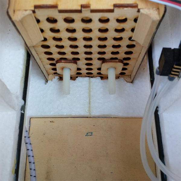
The payload box provides a space to store and secure the payload in the fuselage of the X-UAV Talon. It is recessed into the body of the aircraft through a hole cut in the bottom of the fuselage.
-
The payload box is secured to four mounting brackets glued into the sides of the airframe. Four nylon bolts attach from the outside to hold it in place.
-
The drop mechanism is a servo that extends and retracts a metal pin poking through the side of the body. A bungee cord wraps around the bottom of the payload and attaches to the pin to hold it in place.

Figure 13-3. The bungee secures to the pin of the drop mechanism; the servo retracts the pin to release the bungee and drop the payload
The package is secured inside the airplane by a bungee cord tied at one end to the wooden plate in the nose of the aircraft. It is then stretched across the payload box opening to a pin on the opposite side. When the servo retracts the pin, the bungee will release and drop the payload.
Most of the custom parts were laser cut out of 1/8″ or 1/16″ plywood, with files provided in the Git repository. In the absence of access to a laser cutter, most parts can be cut with hand tools, omitting the grid of holes in the box (done to save weight). SolidWorks part drawings are also available to work from in the repository.
Step #1: Construct Payload Box
-
The payload box provides a space to hold the payload inside the aircraft. It is designed to hold a single 3"×7.5"×6” cardboard box.
-
Assemble the front, back, top and two side plates to make an open-sided box as shown. Secure the parts with wood glue or superglue. The taller side will face towards the front of the aircraft, and will be referred to as the “front” of the box.

-
Attach the bolt plate to the front and rear of the box. The plate must be aligned with the large holes in the front facing side. The plate serves as a mounting point for a pair of 1/4” 20 nylon bolts that will secure the payload box to the mounting bracket.

-
Align the plate so the bolts slot through perpendicular to the box as shown. DO NOT GLUE THE BOLTS TO THE PLATE—the bolts are meant to be inserted after the box has been placed in the airframe.
-
Attach the second bolt plate to the rear of the payload box.

-
(Optional) Strengthen the corners of the payload box with segments of balsa wood.
Step #2: Build Mounting Bolt Assembly
-
The payload box is held inside the aircraft by four nylon bolts that attach from the outside. To give these bolts somewhere to attach to, a mounting assembly attaches to the end of the box.

-
The payload box (1) is attached to the mounting assembly (2), which is attached to the airframe by the bolts (3).

-
Each assembly has two nylon nuts that will hold the external bolts, securing the whole payload assembly to the airframe. Use superglue to assemble three sides of the wooden parts, then glue the nylon nuts inside each end. Then glue the last wooden piece to complete the assembly.
Step #3: Construct Mounting Brackets
-
These brackets give the nylon bolts a place to slot into the side of the airframe. They are long enough to allow some flexibility in how far forward/aft the payload box can be placed. Each bracket is 3” long by 3/4” tall.

-
Assemble the mounting brackets by stacking three of the laser cut pieces as shown and gluing them together.

Step #4: Assemble Front Brace
-
The final custom part is a new front brace for the wooden frame in the center of the fuselage. The new front brace replaces the stock front brace in order to provide enough room to fully insert the payload box into the airplane.

-
Glue the main piece (center) and two of the supports (outsides) together. Install in place of the original kit part. The middle piece fits into the slots for the stock kit front brace.

Step #5: Modify Airframe
-
Cut the payload box hole in the bottom of the airframe. The hole should be along the centerline. The 5.5” from the rear lip is approximate. The hole can be moved more fore/aft to shift the center of gravity. It may be necessary to cut notches for the bolt plate and edges of the box to fit.

-
Then cut the mounting bracket holes. It is important that the mounting brackets are in line with the mounting assembly when the payload box is installed.

-
It is a good idea to install the payload box and take note of the mounting assembly locations before cutting the holes for the mounting brackets. (See Steps 1 and 2.)
-
Cut two 3"× 3/4” rectangular holes in the side of the fuselage to fit the mounting brackets. Adjust the location of the holes fore/aft depending on where the box will finally sit in the airframe.

-
If you are modifying a new airframe, the top of the holes for the mounting braces align with the interior foam molding as shown.
Step #6: Install Front Brace
-
Install the new front brace for the wooden frame. If the kit has not been assembled yet, simply replace the old front brace with the new part when building the wooden frame for the center of the fuselage. If modifying an already built kit, cut the old X brace and glue on the outside pieces from Step 4 to strengthen it.

Step #7: Install Bungee and Payload Box
-
Tie a length of bungee cord to the front plate in the nose. It should be long enough to reach out one front mounting bracket and across the hole cut for the payload to the other side rear mounting bracket (see photo in intro). Feed the other end through one of the front mounting brackets and tie a metal washer on the end.

-
Insert the payload box into the hole cut in the bottom of the fuselage. The tall end faces the front of the aircraft. It should be nearly completely recessed into the airframe.

Step #8: Bolt It In
-
Place two 1” long 1/4” nylon bolts through the holes in the bolt plate on the front and back of the box once it is in the airframe.
-
Note: The bolt plates in the photo are from an older design; see Step 1 for an updated design.

-
Place the mounting assembly over the bolts on the box. Secure with nuts. Secure the payload box with 1.5” long nylon bolts through the mounting brackets into the nuts (as seen in Step 2) in the mounting assembly. 4X: Front and back, and on both sides.