
Highly Accelerated Life Testing
Introduction
Highly accelerated life testing (HALT) is a method used for rapid acceleration of the precipitation and detection of failure mechanisms, latent manufacturing defects, and design weaknesses over time. The failure acceleration occurs through the application of a combination of environmental and electrical stress conditions, such as temperature, vibration, humidity, power, and voltage. HALT and highly accelerated stress testing (HAST) apply accelerated stresses that are applied nonuniformly in varying stress combinations, called step stresses, and various environmental conditions, called load case conditions.
Gregg Hobbs, who pioneered the HALT process and coined the term HALT, states: “In HALT, every stimulus of potential value is used under accelerated test conditions during the design phase of product in order to find the weak links in the design and fabrication processes. Each weak link found provides an opportunity to improve the design or the processes, which will lead to reduced design time, increased reliability, and decreased cost” [1].
Traditional reliability tests such as accelerated reliability testing (ART) and accelerated life testing (ALT) use environmental stresses applied uniformly and consistently to expose failures and to develop acceleration factors to equate the stresses applied in a test to reliability or to life in the actual customer use environment. With HALT, acceleration factors are difficult if not impossible to determine, and test time cannot be correlated to customer use time. The reason that acceleration factors are difficult to develop for HALT data is due to the rapid acceleration of stress conditions and the combination of stress conditions where existing acceleration models are not adequate. This means that test times accumulated in HALT under step stress conditions may not be correlated to customer use times, since the highly accelerated stress levels in HALT are stepped, not steady-state or constant stress levels. For example, the Coffin–Manson equation is used to calculate the acceleration factor from a constant temperature cycling test, which is used to correlate the stress test time to actual application time or failure rates in customer environments. The Coffin–Manson equation would be useful in HALT for a single temperature-cycle step stress condition, but not for the entire temperature-cycle load case, composed of multiple step stresses. HALT focuses on design enhancements and refinements, such as design changes to achieve a reliability improvement instead of focusing on acceleration factors and predicting or demonstrating field reliability. Therefore, HALT does not result in a metric for calculating reliability, such as mean time between failures (MTBF).
HALT is a series of individual and combined load cases and step stresses that are applied in steps of increasing intensity until the product fails or the preestablished limits are reached. Predefined stress limits are selected when the destruction levels are known from previous tests, or when fundamental limits of the technology are known through supplier specifications. Where testing to destruction limits is not necessary, testing may be called highly accelerated stress testing (HAST) instead of HALT. HALT or HAST stresses are typically some combination of the following: single-, double-, or multiaxis random vibration (electrodynamic or repetitive shock), high-temperature step stresses, low-temperature step stresses, temperature cycling (or thermal shock), power cycling, voltage variation, four-corner tests, and humidity. Four-corner tests are testing for two stress conditions simultaneously where stresses are applied at the upper and lower boundaries for each stress, resulting in four stress steps. For example, a four-corner test for stress A and stress B results in a test at the upper limit of stress A with the upper limit of stress B, upper limit of stress A with the lower limit of stress B, lower limit of stress A with the upper limit of stress B, and finally, the lower limit of stress A with the lower limit of stress B.
Humidity is valuable as a stress condition only if moisture exposure is a concern for the product design. Any stress or any stimulus that is deemed product sensitive should be employed. By comparing the stresses to the design strength, measurable design margins are determined. The design margin is also known as the factor of safety (FOS). FOS is the fraction of design capability over the design requirement. There is a direct correlation between the FOS and the measure of the reliability of a particular design. The correlation is a directly proportional relationship, such that as the difference between the stress and the strength increases, the predicted reliability over the life cycle increases. Although this correlation exists, there is still no way to estimate the mean life or mean time to failure (MTTF) or MTBF of the product as a result of the HALT process. To accomplish this, a reliability test such as a reliability demonstration test or reliability development growth test (RDGT) is needed.
RDGT and test analyze and fix (TAAF) tests are similar to HALT but were developed for military products and systems many years before the HALT process development. RDGT provides a quantifiable reliability metric, such as MTBF. Its results may be useful in driving design changes to meet specified reliability requirements. HALT does not replace these types of military reliability tests but, rather, complements these test approaches. Several differences appear in a comparison of the HALT and RDGT approaches. One difference is that HALT finds design weaknesses more quickly than does RDGT. This is accomplished through highly accelerated environmental test methods that provide time compression, which results in precipitating failure mechanisms over a shorter period of time than with RDGT or TAAF. When given a choice, system or product developers should adopt a two-stage reliability test approach, involving reliability demonstrations and HALT. Both approaches have value and offer benefits that complement each other.
Next we explore HALT in detail by examining what HALT is and what it is not, and discuss time compression and test coverage. To understand what HALT is, let us explore multiple factors in end answers to the question: What are the key points of the HALT process?
- Develop HALT with discrete and combined load cases and step stress conditions.
- Employ time compression to find design weaknesses faster.
- Ensure test coverage with internally designed built-in-test capability and the use of adequate external test equipment to detect faults and guarantee high test coverage.
- Understand the capability of the design.
- Define the fundamental limit of technology (i.e., determine the operating and destructive limits).
- Build confidence in the design performance through knowledge of the design margin and factors of safety.
- Precipitate and detect latent failures and defects (i.e., search for the weak links).
- Detect all failure sources (hardware and software).
- Increase stress conditions until a unit fails or is destroyed or to a predefined limit.
- Indicate sensitivity to stresses.
- Determine the product's robustness or improve the product's robustness.
- Correct inherent design and manufacturing process flaws.
- Conduct a failure analysis on every failure.
- Continue HALT through an iterative process (with corrective action, this improves product design margin).
- Determine the size and weight of the equipment to be tested to determine the chamber size and the weight-handling capability of the vibration table.
- Design test fixtures with high mechanical transmissibility and low thermal mass.
- Use HALT to develop highly accelerated stress screen (HASS) and highly accelerated stress audit (HASA) profiles for production testing.
- Establish groundwork for future reliability testing to generate reliability performance metrics.
To consider the meaning of HALT from another angle, let's analyze what HALT is not.
- HALT has no pass/fail criteria.
- HALT is not a qualification test.
- HALT is not intended to find and fix all failures. The failures that affect product reliability should be resolved and an awareness developed of failure modes at stress conditions well beyond the design specification limits.
- HALT is not used to calculate the demonstrated reliability of products. Reliability tests such as accelerated reliability testing or accelerated life testing are used to calculate reliability performance metrics such as mean time between failures.
- HALT is not a method to calculate acceleration factors for failure mechanisms.
- HALT does not always test to destruction limits if the limit is already well understood through vendor data or other analysis. HALT may use preestablished test limits (preset stress limits in the HALT plan).
- HALT does not require a long time, such as weeks or months, to find weaknesses in a product design and suggest fixes in a product design to improve reliability.
As an exercise, consider why HALT became widely accepted in the commercial product design marketplace in the early to mid-1990s.
HALT achieved early acceptance in commercial design applications due to its ability to rapidly identify design weaknesses early in the product development phase. The initial success of HALT resulted from short cycling the design process to determine the design margin and establish design maturity faster than in the traditional reliability test approaches. Short cycling compresses the time spent in development testing by revealing defects and product vulnerabilities faster than common accelerated test methods and their associated acceleration factors. During development testing the precipitation of latent design and manufacturing defects and early life wearout mechanisms are accelerated faster than in the normal evolutionary process of detecting failures in the field (customer use applications).
Time Compression
One key point of HALT is time compression. Time compression in HALT does not result in acceleration factors that may be calculated for any particular stress condition, but does result in the acceleration of failure mechanisms. This time compression results from:
- Stresses that are applied higher than expected in the field application environment
- Stresses that are applied beyond the product design's specifications and operating requirements
- Higher vibration stresses beyond where Miner's criteria can approximate accumulated fatigue damage
- Hotter test conditions and colder test conditions beyond where thermal acceleration models exist to substantiate an acceleration factor for thermal stress conditions
- An increased environmental cycling rate that can be modeled by exponential acceleration of stress versus the number of stress cycles
- Higher-temperature cycling conditions beyond where Coffin–Manson's model is useful for calculating the acceleration factors from temperature-cycling stresses. Coffin–Manson's model is useful when the temperature-cycling stresses are constant and applied uniformly, but this is not the case for HALT because HALT uses accelerated temperature-cycling stress conditions.
Time compression or failure mode acceleration is accomplished through exercising a single stress condition or combinations of stress conditions. These conditions typically are some combination of temperature extremes (hot and cold), temperature cycling (or thermal shock), vibration (typically, three-axis random vibration with six degrees of freedom), mechanical shock, humidity, power, operating profiles, voltage, current, duty cycle, and frequency. Stresses may be applied individually or in various types of combinations, such as combined temperature cycling with voltage cycling and vibration cycling. For each stress condition, an acceleration factor may be calculated and measured. Accelerated life testing (ALT) is performed where one output from this type of test is an acceleration factor based on an acceleration model in terms of test time equated to actual customer use time. For example, ALT with a temperature-cycling slew rate of 10°C per minute may be found to have an acceleration factor of 10, which means that 1 hour of testing is equivalent to 10 hours of customer use in a normal field operating environment. If the ALT condition changes to thermal shock with a slew rate of 100°C per minute, the acceleration factor may be 100 and the value of the time compression increases by a factor of 10 compared to temperature cycling.
Test Coverage
Another key point of HALT is test coverage, which is used to analyze the extent of the ability of the design and external test equipment to identify faults in the hardware being tested. Test coverage is another term for fault coverage or probability of fault detection. It is meant to reveal operational and environmental vulnerabilities. Test coverage is not a method to determine if all the design specification requirements are met by the product or system design, nor is it a test of the product or system to meet its requirements.
In HALT an electronics box, consisting of multiple circuit cards packaged within an enclosure, is exposed to the combined accelerated environments. During this testing, the electronic test points must be accessible to permit monitoring circuit performance parameters. This is done when a formal test station is not available. Test equipment probes are attached directly to test points and circuit traces or component leads to ensure that the design is operating as planned. The duration of each step within a step stress profile is based on the soak time and the length of time required to perform a test. The soak time is the amount of time needed to determine that the equipment under test has reached thermal equilibrium. After the soak time, the additional time in the step is the duration to perform the electrical test on the equipment under test. The amount of stress increase after each step is based on the sensitivity of the equipment to the stresses and how much time the analyst wants to take to determine the fundamental limits of the technology, where the operating design limits are for determining the operating and destruction margins.
Key Points of HALT Test Coverage Analysis
Environmental Stresses of HALT
A critical decision in HALT planning is the selection of HALT step stresses and load cases for various environmental stress conditions. Typical stress conditions in HALT are separated as load cases. Within each load case are step stresses. Stresses may be applied individually or in various types of combinations, such as a combined temperature cycling with voltage cycling and vibration cycling. A typical HALT plan may have six types of test profiles (load cases) with various step stresses. Typical load cases and step stress conditions are:
Figure 1 Temperature-cycle step stress load case.

Any of these load case profiles could be executed with combined electrical operation conditions, power cycling, and input voltage cycling or voltage variation to further strengthen the test capability. Voltage cycling or voltage variation may include:
- On–off cycling
- Input ac or dc voltage static (i.e., margins)
- Input ac or dc voltage dynamics (i.e., dips, interruptions, and variations)
- Frequency margins (applicable mostly for transformer-coupled linearly regulated converters)
An example of a temperature-cycle load case with three step stresses is shown in Figure 1.
Sensitivity to Stresses
A key advantage of HALT is the ability to determine product sensitivity to stress conditions. For any type of load case involving step stress conditions, the HALT engineer should decide how many steps and how large the incremental steps should be. Step stresses may start as large or small steps, depending on how important it is to determine the operating limit versus the destruction limit. The operating limit is the point in HALT where intermittent operation occurs but the product recovers at ambient test conditions. The destruction limit occurs at the stress level where the product cannot recover from a failure mode when operated at ambient levels.
For the example in Figure 1, you will notice that there are three steps between the temperature ranges 0 to 50°C and −40 to 90°C. Each temperature-cycle step stress increase is 40°C. The step increases could have been 10°C or 20°C if the goal of the HALT test was to identify the sensitivity of various failure modes to stresses at various stress levels on the way to the −40 to 90°C range limit. There is nothing scientific in the selection of this step increment other than the speed that it will take to reach the operating or destruction limit. The duration of each step is based on science, however. The step duration is the time it takes to fully exercise or test the function which may be sensitive to the stress. If the test takes 5 minutes to run at each step versus 1 hour at each step, this difference in test time at each dwell period could contribute to the decision to apply larger step increases instead of smaller steps during the load case. The test may be synchronized so that the electrical test profile is out of phase with the temperature cycles so that a certain electrical test step occurs at a different place in the thermal profile.
The HALT analyst determines the sensitivity to stresses by exercising the equipment in small steps in the stress area where operation becomes intermittent. As the test stress is increased in large steps with continuous test stimuli and detection, and the test records degraded performance, the analyst should bring the equipment back to a stress level where reliable operation is restored, and then start the step process again. This time, as the step approaches in the step stress sequence the point at which intermittent operation occurred initially, the stress should be increased in smaller steps, monitoring the performance continuously to determine if the equipment repeats the intermittent operation at the same stress area as recorded previously. This stress area is the condition in HALT where the product potentially has no design margin. If the failure is still intermittent (e.g., soft failure) at the same stress area, the operating limit is verified, and the test stress steps continue beyond this limit to the point where intermittent operation occurs more frequently and then leads to a hard failure condition in which equipment operation does not recover when the stress is reduced to specification levels or lower stress levels under nominal conditions. The destruction limit is the stress level where a hard failure occurs, repeatedly, and may be considered a design weakness that limits product robustness. Two or three product samples should be available for HALT to prove the case for a known destruction limit. At this limit, the fundamental limit of the technology is reached. If only one sample fails and another sample passes at the stress level, which was predicted to be the potential destruction limit, this may demonstrate the case for variability in the manufacturing quality or process of the parts or components supplied, or a potential design weakness.
Test stimulus may be applied in several ways. The test stimulus may be electrical or mechanical measurements recorded based on known test inputs or test signals. Test signals may be injected at specific nodes on the circuit, continuously stressing the circuit. Test meters are used to monitor the circuit outputs and detect failure conditions. Software test routines may be injected into the circuit interface and looped repeatedly to accelerate and precipitate the detection of latent faults, which may be caused by probabilistic failure mechanisms. Looping test routines constantly stressing the circuit functionality within a few hours accelerates the latent faults that would otherwise surface after many months or years of operation by the customer. The failure mechanisms may appear initially as intermittent probabilistic failures, but will increase in frequency of occurrence and become more repeatable with further accelerated testing over time until they become deterministic hard failures.
Time compression or failure mode acceleration is accomplished through exercising a single stress condition or combinations of stress conditions. These conditions result in an acceleration of failure modes, typically with combinations of environmental and electrical step stresses integrated in a single load case test profile, which may include temperature extremes (hot and cold step stresses), temperature cycling (or thermal shock), random vibration (typically, three-axis simultaneous repetitive shock random vibration with 6 degrees of freedom), mechanical shock (such as drop testing), humidity, power, operating profiles, voltage, current, duty cycle, and frequency.
Design Margin
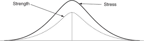
HALT provides a fast means to determine the product design margin between the specification and operating limits, and between the operating and destruction limits. The specification limits are the documented requirements, which highlight the capability of the design. The design margin between the specification limits and the operating limits, also called the operating margin, usually has very little overlap between the design strength and the applied stresses expected for the product. A small overlap between the design strength and the stresses applied translates into no physical fatigue, or physical fatigue that develops slowly over time and stress. This condition is depicted in Figure 2. The area outlined in heavy lines shows where the overlap occurs and reflects the operating area where failures are likely to occur. As the overlap between stress and strength increases, physical fatigue develops more quickly, and the operating area grows where failure probability is likely. Early life wearout mechanisms occur when the physical fatigue accumulates to the point of failure or damage. When the stresses surpass the strength of the design, there is negative design margin, or overstress conditions. In the overstress condition shown in Figure 3, the stress area overlaps the strength area entirely, resulting in a 50% probability that the product will fail when the product is operated. When the design strength becomes greater than the stresses applied, the positive design margin is increased.
Figure 2 Stress-strength overlap.
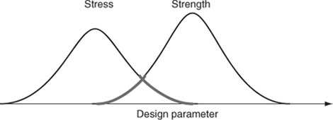
Figure 3 Example of overlap resulting in 50% probability of failure.
For example, if a table was required to withstand weights of 100 lb dropped from a height of 1 foot, one might design the table to handle 200 lb from 1 foot. This increased design strength provides 100% design margin, which has a direct correlation on the high reliability or robustness of the table. The test measurements achieved from HALT output provides results in terms of the percentage of design margin for that product design, which is very useful to the design engineer.
The design margin for thermal performance of the product after completion of HALT may be determined to be 50%, as an example. This 50% design margin means that the design operating limits are 50% beyond the specification limits. For example, if the specification for a particular design states that the operating high-temperature requirement is 100°F, or 30°F above room temperature (70°F), a 50% design margin for high-temperature conditions means that the design will operate reliably up to 115°F (30°F × 0.5 = 15°F) before failures are highly probable.
Using the example above, for a design with 50% design margin, this means that the design is capable of operating at a high temperature that is 50% above the design specification's high-temperature operating requirement. The high-temperature operating limit is the actual level of operation that the design is able to withstand up to intermittent operation and the appearance of soft or hard failures. This level of design margin usually has some amount of overlap between the design strength and the stresses applied. When the design strength does not overlap and exceed the design stresses, no failures will occur. Some distribution of failure points may follow a normal distribution curve. The upper tails of the stress distribution may enter the lower tails of the design strength distribution in some units. When design strength distribution begins to overlap design stress distribution, the design experiences a nonzero probability of failure. As the strength and stress overlap continues, or increases, physical fatigue accumulates at an accelerated rate. Early life wearout mechanisms of a design are precipitated with prolonged stress exposure. When the design performs continuously at the operating limit, the design margin is approaching zero.
The destruction limits are the levels of stress in which intermittent failures increase in frequency until the design fails to operate. This type of failure, which is not able to recover, is called a hard failure or patent failure. At the destruction limit, the design margin is zero and the margin is close to zero. The accumulated fatigue stresses exceed the strength of the design. The physical stress is too much for the design strength to handle. At this level, materials fail (i.e., fracture, melt, or vaporize).
Sample Size
The sample size for HALT is usually one or two units. This decision is based on the cost of the units and knowing that the units will not complete HALT in a condition to be sold to customers. When given a preference, I select three to six samples for HALT. Three samples are the minimum sample size and are initially tested in a sequence or in parallel to identify design weaknesses and early life wearout failure mechanisms that isolate a root-cause failure pattern or trend. If only one unit is HALT tested, it is uncertain if a trend has been detected. If two units exhibit the same failure mode and root-cause mechanism, there is a higher statistical significance that a trend has surfaced compared to a single failure. If three units are tested, this will increase the statistical significance of a trend if all three detect the same failure. It will also result in identification of a trend if two out of three units fail for the same reason.
Once the root-cause resolution is determined and the corrective action implemented to the design, another sample of three units is selected. These may be units that are reworked or repaired from the original test sample population, or it may be three new units built with the design change incorporated at initial assembly production. This depends on how many samples were build for the test phase, on whether there are more units available to conduct a retest of the HALT, and/or on the extent of the design change corrective action.
Conclusions
With repeated HALT, using appropriate environmental and electrical step stress conditions, load cases, and a sufficient number of test samples, HALT is useful to improve product reliability and to assure adequate design margin within customer application environments and stress conditions. This is true only if failures are identified and corrective actions are taken during and after HALT to increase the design margin. Reliability improvements can be made when the design is changed to either increase the design strength or lower the design stress, or both.
Acknowledgment
This chapter was developed from a four-part series of articles on highly accelerated life testing published in four consecutive IEEE Reliability Society newsletters between 2008 and 2009.
Reference
[1] Hobbs, G. K., Accelerated Reliability Engineering: HALT and HASS, Wiley, Hoboken, NJ, 2001.