10
Welded Connections
10.1 Introduction
Nowadays most of the connections in steel structures are carried out using welding since it is efficient and economical. It does not require holes to be made in the members to be connected and can be done without extra material such as plates and angles. Both butt welds and fillet welds may be used for connections. Butt welds are most economical since connecting parts are welded directly without any plates or angles. However, it is not possible to do all the connections in a steel structure using butt welds due to misalignment and misfit during erection. For example, to use a butt weld, in the case of a beam to column connection, the tolerance on the gap between the column and the beam is very stringent. Therefore, it is a usual practice to do butt welding in shops whereas fillet welding may be done in shops or in fields during the erection. However, the quality of welding done in fields is not as good as that done in shops.
The fundamentals of welded connections are presented in Chapter 2. In this chapter, welded connections subjected to combined actions such as shear, bending and twisting are considered. These include bracket connections and beam to column end connections.
10.2 Bracket Connections
Bracket means a steel plate or a set of steel plates connected to columns to support beams. The bracket may be connected to a column using butt or fillet welds. The welds are subjected to a shear force and a bending moment or a twisting moment.
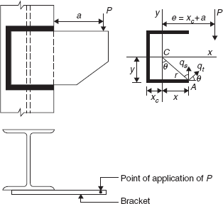
10.2.1 Bracket Connection Using Butt Weld
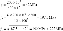
In this type of connection, the butt weld is subjected to a vertical shear force, V = P and a bending moment, M = Pe (Figure 10.1). According to IS800:2007, the butt weld should be provided such that:
where fe = equivalent stress
fb = bending stress in the weld due to factored bending moment
q = shear stress in the weld due to factored shear force
in which lw is the effective length of the weld and for a full penetration butt weld, t = the thickness of the bracket plate.
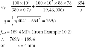
The minimum effective length of the weld to be provided may be approximately calculated by considering only the bending stress in the weld, i.e.
The actual effective length of the weld will be more than the value given by this expression since the weld is subjected to a shear stress too.
10.2.2 Bracket Connection Using a Fillet Weld
There are two ways of connecting a bracket to a column using a fillet weld. The bracket may be connected perpendicular to the flange of a column or in the plane of flange of a column.
10.2.2.1 Bracket Perpendicular to the Flange of a Column
In this case, the bracket is connected to the flange of a column with fillet welds provided on either side of the bracket as shown in Figure 10.2.

The fillet welds are subjected to a factored shear force V = P and a factored bending moment M = Pe due to which shear stresses, in horizontal and vertical directions, are developed in the fillet welds at their throats. The resultant shear stress on the throat of fillet welds is given by
where qb = shear stress due to the bending moment
qs = shear stress due to the shear force
in which tt = effective throat thickness = 0.7s, ‘s’ being the size of weld
lw = effective length of a single fillet weld
For the design of these welds, the resultant shear stress q ≤ fwd
where fwd = design shear strength of the fi llet weld = ![]()
in which fu = ultimate strength of the weld material or parent metal whichever is less
γmw = partial safety factor
= 1.25 for shop welding
= 1.5 for field welding
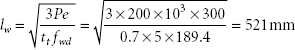
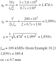
The effective length of weld lw may be obtained approximately by considering the shear stress in the weld due to the bending only.
The actual length of the weld will be more than the value given by this expression since shear stress is also produced due to shear force.
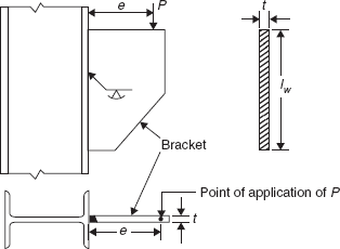
10.2.2.2 Bracket in the Plane of Flange of Column
In this type of bracket connection, the fillet weld is subjected to a shear force V = P and a twisting moment M = Pe. Due to the shear force P, shear stress (qs) is produced at the throat of the fillet weld and another shear stress (qt) is developed due to the twisting moment Pe. The direction of the shear stress qt at any point on the length of the weld is perpendicular to the line joining that point with the centroid C of the weld. This is shown in Figure 10.3 for a point A where the magnitude of the shear stress qt is maximum since the point A is the farthest from the centroid C.
The shear stress qs due to the shear force V = P is given by
where lw is the total length of the weld and tt is the effective throat thickness of the weld.
The maximum shear stress qt due to the twisting moment M = Pe is obtained at the point A in the weld using
where Ip is the polar moment of the effective weld section, r is the distance of the farthest point A from the centroid C and e is the eccentricity of the load.
To find the resultant shear stress q in the weld at a point A, qt is resolved into components along the x and y axes.
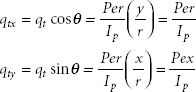
Since both qs and qty act vertically, the components of stress at a point A along the x and y axes are given by
Finally, the resultant maximum shear stress on the throat of the weld is obtained from
which should be less than or equal to the design shear strength of the fillet weld fwd.
Example 10.1
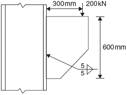
Design a connection for a bracket using the butt weld to carry a factored vertical load of 200 kN acting at 300 mm from the face of the column. The grade of the steel is E250.
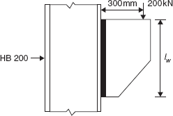
Let the thickness of the bracket, t = 12 mm
Minimum depth of the bracket is given by
A bracket of depth of 500 mm may be tried.
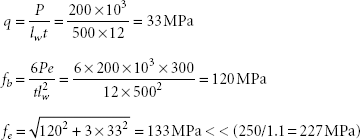
The depth of the bracket may be reduced to 400 mm.
Hence, 400 mm deep and 12 mm thick bracket may be provided which may be welded to the column using a full penetration butt weld.
Example 10.2
Re-do Example 10.1 using fillet welds. fy = 250 MPa and fu = 410 MPa
The thickness of the bracket may be 12 mm as in Example 10.1. To connect a 12 mm thick bracket, the minimum size of the fillet weld is 5 mm (from Chapter 2).
The effective length of the fillet weld required,
A bracket of depth of 600 mm may be tried.
Then, the effective length of the fillet weld provided, lw = 600 − 2 × 5 = 590 mm
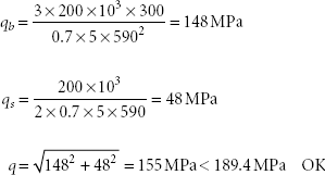
Therefore, a bracket of 600 mm depth connected by 5 mm size fillet welds on either side as shown in Figure 10.5 may be provided.
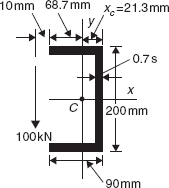
Example 10.3
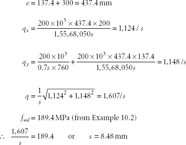
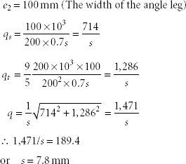
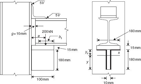
Re-do Example 10.1 if the bracket is connected in the plane of the flange of a column by a fillet weld. The width of the flange of the column is 200 mm. fy = 250 MPa and fu = 410 MPa.
A bracket with the dimensions as shown in Figure 10.6 may be tried.
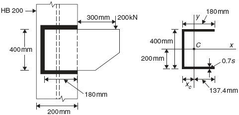
The total length of the weld provided = 400 + 2 × 180 = 760 mm
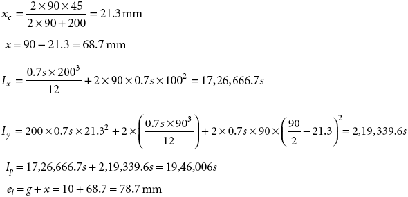
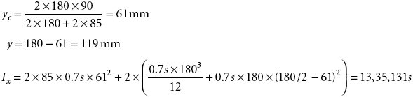
The distance of the centroid of the weld,
The moment of inertia of the effective section weld about the x-axis
The moment of inertia of the effective section weld about the y-axis
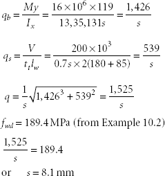
The polar moment of inertia of the weld, Ip = 1,38,13,333s + 1,75,47,175s = 1,55,68,050s
A 10 mm size fillet weld may be provided.
10.3 Simple Beam End Connections
Simple beam end connections mean connections which only transfer the end shear to columns. The connections are almost flexible and practically transfer no moment to the columns. Some of the commonly used simple beam end connections are considered here.
10.3.1 Web-angle Connection
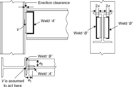
In this type of connection, two angles are provided each on either side of the web of a beam. Usually, one leg of each angle is connected to the web of a beam by a shop weld ‘A’ and another leg of the angle is connected to the flange or the web of a column by a field weld ‘B’ as shown in Figure 10.7. The angles are provided near the compression flange of a beam to provide a lateral support.
The thickness of the angle provided should be at least 4/3 of the size of the fillet weld since for a rounded edge, the size of the weld should not be greater than 3/4 the thickness of the angle. The depth of angles (d) is generally kept between 1/2 and 2/3 of the depth of a beam. For the design of welds, it is assumed that the end shear of a beam is transferred to the supporting member at its face.
10.3.1.1 Design of Shop Weld ‘A’
The shop weld ‘A’ is subjected to a shear force of V/2 and a twisting moment of Ve1/2, where V is the end shear transferred by a beam and e1 is the eccentricity of the shear force V/2 from the centroid of the weld. Therefore, the shop weld ‘A’ is designed as explained in Sec. 10.2.2.2.
10.3.1.2 Design of Field Weld ‘B’
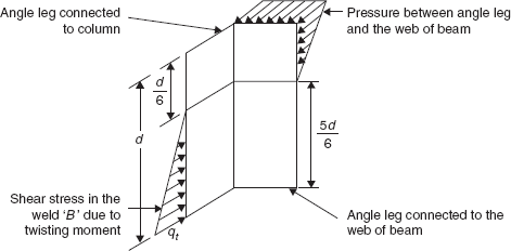
Again, the field weld ‘B’ is subjected to a shear force of V/2 and a twisting moment of Ve2 / 2, where e2 is the eccentricity of the shear force V/2 from the centre line of the weld. It is assumed that this twisting moment is resisted by the pressure produced between the angle leg and the web of a beam and by the shear stress produced in the weld ‘B’ as shown in Figure 10.8.
The shear stress qs in the weld ‘B’ due to the shear force is given by
where lw = d, if the welds are returned at the ends and tt is the effective throat thickness of the weld.
The maximum shear stress qt produced in the weld ‘B’ due to the twisting moment is obtained as shown below.
or
The resultant shear stress q in the weld ‘B’ is
which should be less than or equal to the design shear strength of the weld fwd. The weld ‘B’ should be returned at the top for a length 2 times the size of the weld to prevent the formation of craters.
10.3.2 Seat-angle Connection
In this type of connection, the beam rests on the horizontal leg of an angle which acts as a seat. The other leg of the angle is connected to the flange/web of a column or any other supporting member as shown in Figure 10.9 by vertical fillet welds.
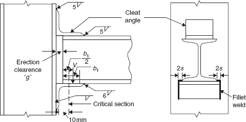
The contact length b1 between the beam and the seat-angle is calculated from the web crippling consideration. That is from Clause 8.7.4 of IS 800:2007,
or
where V = factored end shear from the beam
n2 = 2.5 (R1 + tf)
in which R1 = radius at the fillet/root of the beam
tf = thickness of the flange of the beam
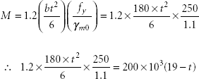
The factored end shear V acting on the horizontal leg of the seat-angle is assumed as uniformly distributed over the contact length b1. Therefore, V acts at a distance b1/2 from the end of the beam. The bending moment M in the horizontal leg of the seat-angle is calculated at a critical section which is 10 mm from the face of the vertical leg of the seat-angle. That is
If the erection clearance g = 10 mm,
where t is the thickness of the seat-angle.
The ultimate moment capacity of the horizontal leg of the seat-angle is given by
where b = length of the seat-angle
From Equations (10.19) and (10.20), the thickness of the seat-angle is calculated. The vertical fillet welds connecting the seat-angle to the supporting member are designed as in Sec. 10.2.2.1 for the vertical shear force V and the bending moment V (g + b1/2). The welds should be returned at the top for a length 2 times the size of weld to prevent the formation of craters. The beam is tack welded by 6 mm fillet welds to the seat-angle to keep it in position. A top cleat angle ∠ 100 100 × 8 is provided and is connected by 5 mm fillet welds to provide torsional restraint.
10.3.3 Stiffened Seat Connection
When the end shear from a beam is high, the required thickness of the seat-angle will be more. The angle with the required thickness may not be available. In such a case, a stiffened seat connection is provided. In this type of connection, as shown in Figure 10.10, the horizontal and vertical plates are used to support a beam. The horizontal plate acts as a seat whereas the vertical plate stiffens the horizontal plate thereby reducing its bending. The two plates are connected by welding.
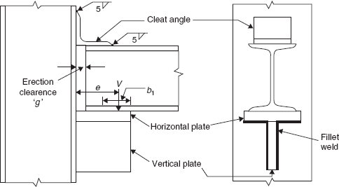
The width of the vertical plate is governed by the web crippling of the beam. The thickness of the horizontal plate should not be less than the thickness of the flange of the beam and the thickness of the vertical plate should not be less than the thickness of the web of the beam. The dimensions of the vertical plate should be such that it does not buckle. The vertical and horizontal plates are connected to the flange of column by fillet welds on both edges of the vertical plate and on the lower edge of the horizontal plate. The fillet welds are subjected to a vertical shear force and a bending moment. The contact length b1 is obtained as in Sec. 10.3.2 but it is now measured from the edge of the vertical plate as shown in Figure 10.10.
Example 10.4
Design a web-angle connection for a beam MB 350 @ 52.4 kg/m which transfers a factored end shear of 200 kN to the flange of the column HB 300 @ 63 kg/m. fy = 250 MPa and fu = 410 MPa.
2 ∠ 100 100 may be used as web angles on either side of the web of the beam. The height of the angle may be 200 mm (0.57 times depth of beam). An erection clearance (g) of 10 mm may be assumed.
Shear transferred by each angle = V/2 = 200/2 = 100 kN
Design of weld ‘A’
The weld provided is shown in Figure 10.11.
From Equation (10.11),
From Equation (10.12),
Design of weld ‘B’
The thickness of the angle = 4/3 × 7.8 = 10.3 mm
Hence, 2 ∠ 100 100 × 12 web angles may be used connected by welds A and B of sizes 5 mm and 8 mm, respectively.
Example 10.5
Re-do Example 10.4 using a seat-angle connection.
From Appendix A, for MB 350, R1 = 14 mm, tf = 14.2 mm and tw = 8.1 mm.
n2 = 2.5 (R1 + tf) = 2.5 (14 + 14.2) = 70.5 mm
![]()
The minimum width of the horizontal leg of a seat-angle = g + b1 = 10 + 38 = 48 mm
The bending moment in the horizontal leg of a seat-angle, 
Since the width of the flange of the beam MB 350 is 140 mm, the length of the seat-angle may be 180 mm which is less than the flange width of the column HB 300, i.e. 250 mm.
The ultimate moment capacity of the horizontal leg of the seat-angle
or t = 12.6 mm
∠ 130 130 × 16 may be provided as the seat-angle.
The bending moment acting on the fillet welds 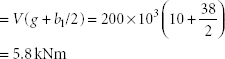
Fillet welds of the size 10 mm (< ¾ th of the angle thickness) may be provided which should be returned for the length of 2 × 10 = 20 mm at the top of the vertical legs of the seat-angle as shown in Figure 10.9.
Example 10.6
Re-do Example 10.4 using a stiffened seat connection.
As in Example 10.5, b1 = 38 mm
A horizontal plate of width 100 mm and thickness 15 mm (not less than tf = 14.2 mm of beam MB 350) and the length 180 mm may be provided.
The thickness of the vertical plate may be 10 mm (not less than tw = 8.1 mm of beam MB 350). The depth of the vertical plate should not be greater than 18.9εt (from Table 1.7 for a stem of T section) i.e., 18.9 × 1 × 10 = 189 mm. Therefore, a depth of 180 mm may be provided to the vertical plate.
For the welds shown in Figure 10.12
The eccentricity of the end shear, e = 100 − 38/2 = 81 mm
The bending moment, M = 200 × 103 × 81 = 16 kNm
A 9 mm size fillet weld may be provided.
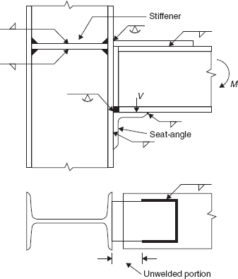
10.4 Moment Resistant Beam End Connection
Rigid joints are encountered in single storey portal frames and multi-storey building frames. Such joints transfer both the end shear and the end moment from a beam to a column. Usually, separate connections are provided to transfer the shear and the moment. To transfer the end shear, a suitable connection described in Sec. 10.3 may be used whereas to transfer the end moment, a typical connection is shown in Figure 10.13. The bottom flange of a beam may be directly butt welded to a flange of the column and the upper flange is connected by a plate. The plate which is subjected to tension is connected to the flange of the column by a full penetration butt weld. The length of the plate should be such that the length of the unwelded portion is not less than the length of the welded portion. The unwelded portion is essential so that the plate yields and imparts ductility to the connection before the failure of the connection. Stiffeners are provided to the column where the plate is welded as shown in Figure 10.13 to prevent the deformation of the flanges of the column.
Example 10.7
A beam MB 350 @ 52.4 kg/m transfers a factored end shear of 200 kN and a factored end moment of 50 kNm to a column HB 300 @ 63 kg/m. Design the connection. fy = 250 MPa and fu = 410 MPa.
To transfer a factored end shear of 200 kN, the same seat-angle connection designed in Example 10.5 may be used.
To transfer a factored end moment of 50 kNm, the connection shown in Figure 10.13 is provided.
The tension in the plate (provided at the top flange)
The required sectional area of the plate = ![]()
Using a plate of width of 100 mm, the thickness of the plate = 629/10 = 6.29 mm
A plate 100 mm wide and 8 mm thick may be provided.
Using a 6 mm size fillet weld to connect the plate to the flange of MB350, the length of the weld required = 143 × 103/0.7 × 6 × 189.4 = 180 mm (∵ fwd = 189.4 MPa)
Since the width of the plate is 100 mm, the length of the weld on each side of the plate may be 50 mm.
∴ The total length of the plate = 100 + 2 × 50 = 200 mm > 180 mm
OK
The unwelded length of the plate may be 100 mm (equal to the width of the plate) with a welded length of 50 mm on either edge of the plate.
∴ The length of the plate = 100 + 50 = 150 mm
Stiffener of thickness 8 mm (equal to the thickness of a plate) may be provided on side of web of the column connected by a 5 mm size fillet weld to the flanges and the web of the column.
Problems
For the following problems, consider the grade of the steel as E250
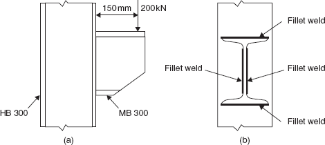
- Design the connection for a bracket cut from MB 300 to HB 300 as shown in Figure 10.14 using a fillet weld as shown.
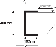
- If the size of the fillet weld in Figure 10.15 is 5 mm, find the factored load P.
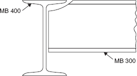
- A secondary beam MB 300 is to be connected to the web of the main beam MB 400 at right angle so that the flanges of both the beams are at the same level (Figure 10.16). The secondary beam transfers a factored end shear of 150 kN. Design a web-angle connection.
- If the beam in Problem 10.3 is connected to the web of a column HB 300, design a seat angle connection.
- A beam MB 500 transmits an end factored shear of 300 kN to the flange of a HB 400 column. Design a stiffened seat connection.
- 10.6 A beam HB 300 transfers a factored end shear of 150 kN and a factored end moment of 120kNm to the flange of a HB 400 column. Design the welded connection.