2
Structural Steel Fasteners
2.1 Introduction
One of the important aspects of steel structures is the joining of various members of a structure so that they act as an integral unit. The different techniques used to join steel members are riveting, welding and bolting. Riveting is the age-old practice of connecting metal parts which has been, to a large extent, replaced by welding and bolting. Except for a very brief note on riveting in this chapter, it is not further considered in this textbook.
2.2 Riveting
A rivet is a ductile steel pin with a manufactured head at one end and a straight portion known as shank (Figure 2.1(a)). Riveting is the process of the driving of rivets into the holes made in the metal parts so that the metal parts are inseparable. Usually, the top surface of the head is round. The round heads of the rivets project from the surfaces of the metal parts which may be undesirable sometimes. To overcome this, countersunk rivets may be used, the heads of which flush with the surface of the metal parts. The straight portion of a rivet is called a shank.
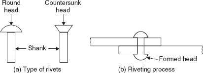
The process of riveting starts with the drilling of holes into the metal parts to be joined, the diameters of which are slightly greater than the diameter of the shank of the rivet. The rivet is heated uniformly in a furnace so that it becomes red hot. Then, it is inserted into the holes drilled in the metal parts. The projected portion of the shank is given a few rapid blows so that another head is formed at the other end of the shank. On cooling, the rivet contracts in length so that the plates are firmly in contact (Figure 2.1(b)). After this process, the shank diameter increases and the shank tightly fits into the hole. Normally, the rivets are driven by the pneumatic process.
2.3 Welding
Welding is the process of joining of metal parts by establishing a metallurgical bond between them. The portions to be joined are brought to a liquid state, thereby making them to establish bond with the help of weld metal. After cooling, the liquid state becomes a solid state and hence the metal parts are joined together. The heat required to make the metal parts melt may be produced either through an electric arc or the oxy-acetylene gas. Structural welding is done mostly by the use of the electric arc called arc-welding. There are two types of arc-welding processes. They are shield metal arc-welding and automatic submerged arc-welding. For welding in the field or for small work in shops, the shield metal arc-welding process is used, whereas for large work in shops, the automatic submerged arc-welding process is used.
2.3.1 Shield Metal Arc-welding
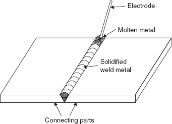
In this method, weld metal is obtained by melting steel rods known as electrodes. The electrodes have a coating of flux which melts along with the weld metal thereby developing a thick gaseous shield. The shield so developed prevents the oxidation of the metal in the liquid state and the loss of heat energy. Quality welds are obtained using coated electrodes rather than bare steel rods. The metal parts to be welded and the electrode are electrically connected to the terminals of a welding machine. An arc is formed when the electrode is brought near the metal parts to be joined. Tremendous heat is generated by the arc which melts small portions of the metal parts and the electrode. After cooling, the metal parts are joined together firmly by weld metal but the melted electrode coating solidifies as slag on the solidified weld metal. The slag may be removed by gentle hammering and wire brushing. The process of shield metal arc-welding is shown in Figure 2.2.
2.3.2 Automatic Submerged Arc-welding
This method is used for large works in a shop. In this method, the arc is not visible. A motor feeds the electrodes automatically at a desired frequency, voltage and arc length thereby producing a sound weld. Multiple electrodes may be used. The use of large electrodes with higher currents is economical for large works.
2.3.3 Types of Welds
Depending on the way metal parts are connected, two types of welds are commonly used in structural work. They are Butt weld and Fillet weld.
2.3.3.1 Butt Weld
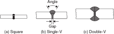
When two metal parts are to be connected directly without any lap, the type of weld used is known as butt weld. The efficiency of the joint depends on the penetration of the weld at the joint. So as to make full penetration of the weld at the joint, i.e., to allow the electrode through the thickness of the metal parts, the ends of the metal parts to be joined are machined to form a groove with a slope of 45° to 60°. This is needed if the thickness of the parts is more. As the weld metal shrinks or contracts after cooling, a gap between the metal parts is provided to facilitate contraction. Otherwise, residual stresses are produced in the weld. Generally, a gap of 1 to 3 mm is provided. Depending on the type of the groove, butt welds are called as square, single-V, double-V etc. (Figure 2.3). To connect two metal parts of different thicknesses or widths, the thickness or width of one of the parts is reduced near the connection. Since the weld metal has more strength than the base metal, the strength of butt welds may be greater than the metal parts provided the welding is done according to the standard specifications.
2.3.3.2 Fillet Weld
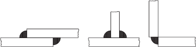
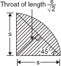
If the metal parts are to be welded with a lap or in the form of a T or L, the type of weld used is known as fillet weld (Figure 2.4). The cross section of the weld is idealized as a right angle triangle with equal sides ‘s’ known as the size of the weld (Figure 2.5). The weakest section in the fillet weld cross section is known as the throat whose length is the perpendicular distance from the right angle corner to the hypotenuse. Fillet welds may be made by a single pass or multiple passes of the electrode depending on the size of the weld.
2.3.4 Quality of Welds
Quality welding requires good workmanship in the shop and field. The correct size and chemical composition of the electrode, the sequence and number of passes in welding, the proper speed, voltage and current for the welding and the preparation of the surfaces play a major role in the quality of the weld. The major defects which may arise due to improper welding are explained in the following.
2.3.4.1 Weld Defects
2.3.4.1.1 Undercutting
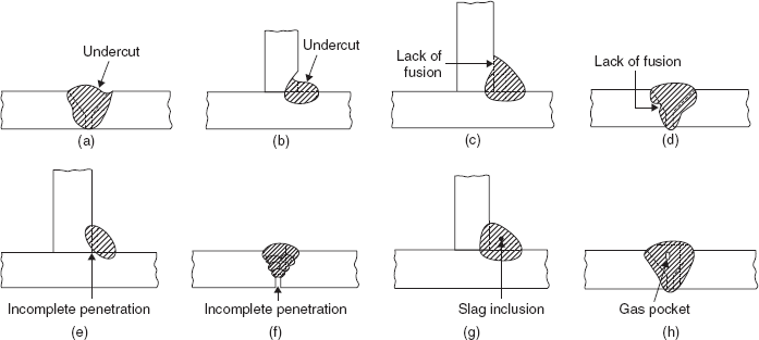
It is the harmful cutting of the base metal due to the position of the electrode, excessive current and the excessive length of the arc (Figure 2.6(a) and (b)). This can be corrected by placing additional weld metal after surface cleaning.
2.3.4.1.2 Lack of Fusion
It is the lack of fusion between the base metal and the weld metal at some points (Figure 2.6(c) and (d)). This is not a common problem and it can be ensured that complete fusion takes place if the surfaces to be welded are properly cleaned and the electrode size, speed and current are properly maintained.
2.3.4.1.3 Incomplete Penetration
It is the fusion not taking place at the root (Figure 2.6(e) and (f)). This may be due to excessive root face, insufficient root gap or groove angle, large size electrode, higher speed or low current. This defect should be avoided as it causes stress concentration under the load and cracks may develop due to shrinkage.
2.3.4.1.4 Slag Inclusions
Metallic oxides and other solid compounds may be trapped in the weld as elongated or globular inclusions (Figure 2.6(g)). The formation of these oxides can be minimized by ensuing that the chemical composition of the electrode metal and the coating does not react with the elements of the base metal.
2.3.4.1.5 Porosity
It is the presence of globular voids or gas pockets in the solidified weld metal (Figure 2.6(h)). Porosity is generally due to excessive current or excessive arc length.
2.3.4.2 Quality Control
Quality welding can be obtained by using the proper welding procedure and welding is done by competent welders. The methods which can be used to assess the quality of the weld are visual, magnetic particle, dye penetrant, ultrasonic and radiographic. To know the adequacy of the weld, various gauges are available. Internal defects such as the lack of fusion or penetration, porosity and slag inclusions can be detected using radiographic photographs of the weld. IS 822:1970 laid down procedures for the inspection of welds.
2.3.5 Weld Symbols and Notation
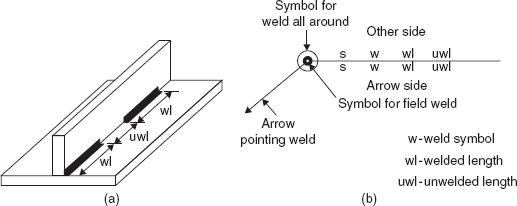
The standard symbols used to indicate a few types of butt welds and fillet weld are given in Table 2.1. Sometimes, a continuous weld is not provided for economy. In such a case, intermittent welds are provided as shown in Figure 2.7(a). The standard notation used to detail welds is given in Figure 2.7(b).

2.3.6 Specifications for Welding as per IS 800:2007, IS 816:1969 and IS 9595:1996
2.3.6.1 Butt Welds
- The size of the butt weld is specified by the effective throat thickness.
- Effective throat thickness: Thickness of thinner part joined for complete penetration of butt weld.
- Effective length: The full length of the weld when run-on and run-off plates are used on either side for a length not less than 40 mm and removed by machining. It should not be less than 4 times the size of the weld.
- Effective area: Effective length × effective throat thickness.
- The butt weld is designed by treating it as the parent metal with a thickness equal to the effective throat thickness and stresses should not exceed those in the parent metal.
- Intermittent butt welds should have the length of not less than 4 times the weld size. The longitudinal spacing between the welds should not be more than 16 times the thickness of the thinner part joined.
- Sufficient surface convexity shall be provided, known as reinforcement, to ensure the full cross-sectional area at a joint. The reinforcement shall not be considered as part of the throat thickness and may be removed to give a flush surface.
2.3.6.2 Fillet Welds
- Size of the weld, s ≥ 3 mm.
- When a fillet weld is applied to a square edge of a part or section, s ≤ 1.5 mm less than the edge thickness.
- When a fillet weld is applied to a rounded toe of a rolled section, s ≤ ¾ of the thickness of the section at the toe.
- The minimum size of the fillet weld should be as given below to avoid cracking in the absence of preheating.
Thickness (t) of thicker part in mm
s (mm) t ≤ 10
3 10 < t ≤ 20
5 20 < t ≤ 32
6 32 < t ≤ 50
10 (8 mm for first run) t > 50
(special precautions like pre-heating should be taken) - Effective throat thickness: ≥ 3 mm
≤ 0.7 × thickness of thinner part joined
For stress calculations, effective throat thickness = Ks, where K depends on the angle between the fusion faces. Usually, the angle is 90° for which
 .
. - Effective length of a fillet weld = (actual length −2s) ≥ 4s
- Length of end returns should not be less than 2s (Figure 2.8).
- In lap connections, the minimum length of the weld should not be less than 4 times the thickness of the thinner part joined or 40 mm – whichever is more. If only side fillets are used, the length of the weld on either edge should not be less than the transverse spacing between the welds.
- The throat thickness of the end fillet weld, normal to direction of force, should not be less than 0.5t where t is the thickness of the part.
- For intermittent fillet welds,
effective length (wl) ≥ or 4s or 40mm, whichever is greaterclear spacing (uwl) ≤ 12t(for compression)≤ 16t (for tension)≤ 200 mm
where t is thickness of thinner part joined.
- Design shear strength of a fillet weld, ƒwd = ƒwn / γmw (2.1)
where ƒwn = nominal shear strength of fillet weld
 fu being the ultimate strength of the weld or the parent metal
γmw = partial safety factor
= 1.25 for shop welding
= 1.5 for site welding
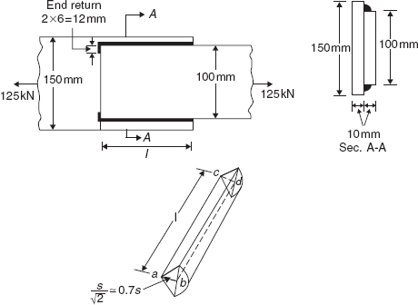
Determine the size and effective length of the side fillets to connect two plates with cross sections of 150 × 10 mm and 100 × 10 mm which are subjected to a tension of 125 kN at working load. The ultimate strength of the plates, ƒu = 410 MPa.
Design load = γf × Tension at working load = 1.5 × 125 = 187.5 kN
Design shear strength of the weld, fwd = fwn / γmw ![]() = 189.4 Mpa
= 189.4 Mpa
Since the plate thickness is 10 mm, the minimum size of the weld = 3 mm and the maximum size of the weld = 10 – 1.5 = 8.5 mm (as per points 2 & 4 in Sec. 2.3.6.2).
So, 6 mm size weld may be used i.e. s = 6 mm
Let l be the effective length of each weld. It is determined such that the design shear force carried by the welds is equal to the design load acting on the welds.
i.e. (Shearing area at the throat) × (Design shear strength of the weld) = Design load
| Since there are 2 welds, | 2 × (area abcd) × ƒwd = Design load |
| 2 × (0.7 × 6 × l) × 189.4 = 187.5 × 10³ | |
| From which, | l = 118 mm > Spacing between the welds = 100 mm |
|
OK |
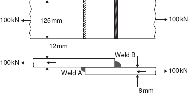
Determine the sizes of end fillets to connect two plates with cross sections of 125 × 8 mm and 125 × 12 mm which are subjected to a tension of 100 kN at working load. The ultimate strength of the plates, ƒu = 410 MPa.
Design load = 1.5 × 100 = 150 kN
Design shear strength of the weld, ƒwd = 189.4 MPa (same as in Example 2.1).
Let the sizes of the welds A and B are in the ratio of the thicknesses of the plates.
i.e., sA /sB = 8/12 ⇒ sB = 1.5 sA
Since the thickness of the thicker plate is 12 mm, minimum size of weld = 5 mm (as per point 4 in Sec. 2.3.6.2).
For the calculation of the effective length of the weld, let sA = 5 mm and sB = 1.5 × 5 = 7.5 mm
Let FwdA and FwdB be the design shear forces carried by the welds A and B, respectively.
FwdA = (Shearing area at the throat) × (Design shear strength of the weld)
= (Effective length of the weld × 0.7sA) × fwd
= (125 − 2 × 5) × 0.7sA × 189.4
= 15246.7sA
Similarly, FwdB = (125 − 2 × 7.5) × 0.7sB × 189.4 = 14,583.8sB
The tension is resisted by both the welds A and B.
∴ FwdA + FwdB = Design load
15,246.7sA + 14,583.8sB = 150 × 103
15,246.7sA + 14,583.8 × 1.5sA = 150 × 103
or sA = 4 mm
and sB = 1.5 × 4.0 = 6 mm
But, as per the 9th point in Sec. 2.3.6.2,
0.7 sA > 0.5 × 8 from which sA = 5.7 mm and 0.7 sB > 0.5 × 12 from which sB = 8.6 mm.
∴ The welds A and B may be of sizes 6 mm and 9 mm, respectively.
Example 2.3
In a truss, ∠ 100 100 × 8 is subjected to the factored tension of 200 kN. It is to be connected to a gusset using fillet welds at the toe and back. Find the lengths of welds required so that the centre of gravity of the welds lies in the plane of the centre of gravity of the angle. ƒu = 410 MPa.
As in Example 2.1, ƒwd = 189.4 MPa.
Gusset is a piece of plate to which various members at a joint are connected, especially, in a truss. Its thickness is usually greater than the thickness of the members. From Appendix A, the distance of centroid from the back of the angle, Cz = Cy = 27.6 mm.
Let l1 be the effective length of fillet weld on the back of the angle and l2 be the effective length of weld on the toe of the angle.
Let F1 be the design shear force in the weld of effective length l1 and F2 be the design shear force in the weld of effective length l2.
Size of weld, s ≤ ![]() × 8 = 6 mm (point 3 in Sec. 2.3.6.2)
× 8 = 6 mm (point 3 in Sec. 2.3.6.2)
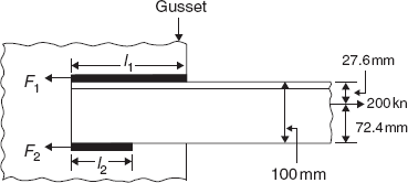
∴ size of the weld(s) may be 6 mm.
Equilibrium equations:
or
Taking moments about a point on the line of action of F1
or 795.5l2 = 55,200
or l2 = 69.4 mm
and l1 = 251.4 − 69.4 = 182 mm
Even though this is the exact way of providing the lengths of welds at the toe and the back of an angle, generally, equal lengths of welds are provided to make the calculations simple.
2.4 Bolting
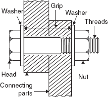
A bolt is a metal pin with a head at one end and the shank threaded at the other end to receive a nut as shown in Figure 2.11. To connect two parts of steel members, holes of suitable sizes are made into the parts and the bolts are inserted into the holes and the nuts are threaded. Usually, steel washers are used under the head and nut to distribute the clamping force on the bolted member and also to prevent the threaded portion of the bolt from bearing on the connecting parts.
Generally, structural bolts may be classified as shown below.
- Unfinished or turned, depending on the type of shank.
- Ordinary structural or high-strength, depending on the material and the strength.
- Square or hexagonal or regular or heavy, depending on the shape of the head and the nut.
- Standard or coarse or fine, depending on the pitch and the fit of the thread.
Unfinished bolts (also known as black bolts) are forged rolled steel round bars and have large tolerances on shank and thread dimensions. For these bolts, therefore, holes are punched or drilled with a diameter of about 1.5−2 mm more than the nominal bolt diameter. Unfinished bolts have adequate strength and ductility when used properly. However, while tightening the nut snug tight i.e., the tightness that exists when all the plies in a joint are in firm contact, may twist off easily if tightened too much. Under dynamic loads, the nuts are liable to become loose and so these bolts are not used under such loadings. Also, in situations in which small slips can cause significant effects like in beam splices, these bolts are not preferred. However, due to the lower cost of the bolt and its installation, black bolts are commonly used in structures subjected to static loading. When a tight fit is needed holes are reamed or drilled and the bolts are turned or finished. These bolts have uniform shanks and are inserted in close tolerance holes and made tight by box spanners. Both these types of bolts, unfinished and turned, are made of carbon steel.
High-strength bolts provide extremely efficient connections and perform well under fatigue and dynamic loads. The tension in the bolts ensures that no slip takes place under working conditions and connections using these may be designed such that the load transmission is entirely through friction and not by bearing. High-strength bolts are made from carbon steel or alloy steel quenched and tempered with or without additives like boron, manganese, chromium. High-strength nuts and hardened washers are to be used with these bolts.
The Bureau of Indian Standards standardized the bolts as shown below:
- Bolts of product grades A & B (Turned/Finished bolts), IS 1364 (Part 1): 2002
- Bolts of product grade C (Black bolts), IS1363 (Part 1):2002
- High-strength bolts, IS 3757:1985
Product grade refers to the size of tolerances. Product grade A is the most precise and grade C is the least precise. In steel structures, bolts of product grade C and high-strength bolts are commonly used. For suitable nuts, reference has to be made to IS 1364 (Part 3 to 6):2002, IS 1363 (Part 3), IS6623:1985. For washers, reference may be made to IS6610:1972 and IS 6649:1985.
The technical details of the various bolts like tolerances and mechanical properties may be found in IS 1367:2002. According to this standard, the bolts are classified into property classes 3.6, 4.6, 4.8, 5.6, 5.8, 8.8, 9.8, 10.9 and 12.9 depending on the strength. Here, the number before the decimal indicates 1/100th of the nominal tensile strength in MPa and the number after decimal indicates 10 times the ratio between the yield strength and the nominal tensile strength. Bolts of property class 8.8 and above come under the high-strength category. In steel construction, bolts of property classes 4.6, 5.6. 8.8 and 10.9 are generally used.
2.4.1 Types of Failure
The bolted connections made using bolts of product grades A, B & C may fail in the following ways.
2.4.1.1 Shear failure of bolt (Figure 2.12)
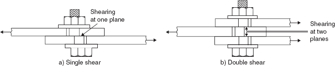
A bolt may fail due to shearing. The shearing may take place at one section (known as single shear) or two sections (known as double shear) depending on the type of connection.
2.4.1.2 Bearing failure of bolt / plate (Figure 2.13)
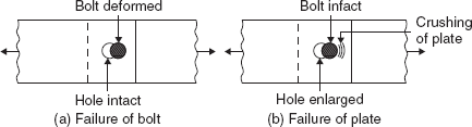
The force in the connecting parts is transferred through the bolts by bearing action. Due to this action, the portion of the plate in contact with the bolt may get crushed and/or the portion of the bolt in contact with the hole edge may get deformed.
2.4.1.3 Rupture of plate (Figure 2.14)
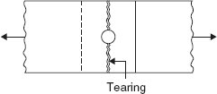
This type of failure takes place along the weakest section of the plate due to the presence of holes. It may be prevented by having fewer holes at a section or the holes may be staggered. The tensile strength of a connection depends on the net sectional area of the plate.
2.4.1.4 Tension failure of bolt (Figure 2.15)
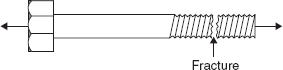
In some connections, the bolts may be subjected to tension. Fracture may takes place at the root of the thread since it is the weakest section.
2.4.1.5 Block Failure of Plate (Figure 2.16)
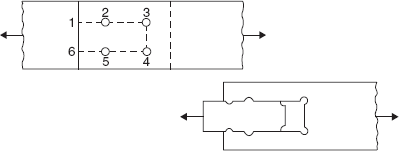
A portion of the plate may fail by shearing and rupture known as block failure. The shearing of the block takes place in the direction of the force (along 1–2 – 3 and 4–5 – 6) whereas the rupture of the block takes place perpendicular to the direction of force (along 3–4).
2.4.1.6 Shear Failure at Plate End (Figure 2.17)
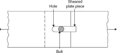
This type of failure occurs when there is an insufficient end distance, i.e. the distance from the end of the plate to the centre of the nearest hole measured in the direction of the force. This type of failure may be avoided by providing enough end distance.
2.4.2 Design Specifications for Bolted Connections as per IS 800:2007
2.4.2.1 Shear Capacity of a Bolt
The design strength of a bolt in shear Vdsb is given by
Vnsb = the nominal shear capacity of a bolt
where
fub = the ultimate tensile strength of the bolt
nn = the number of shear planes within the threading of a bolt
ns = the number of shear planes within the shank of a bolt
Asb = the sectional area of the shank of a bolt (Table 2.2 )
Table 2.2 Sectional area of shank (Asb) and net shear area or net tensile stress area (Anb) of bolts
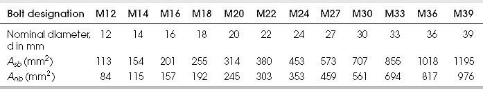
Asb = πd2/4: Values Anb are from IS 1367 (Part 3):2002
Anb = the net shear area of a bolt (Table 2.2)
γmb = the partial safety factor for bolts = 1.25
2.4.2.2 Bearing Capacity of a Bolt
The design strength of a bolt in bearing Vdpb is given by
where Vnpb = the nominal bearing strength of a bolt
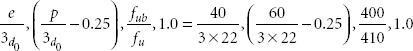
kb is the smallest of ![]()
e = end distance
p = pitch
d0 = diameter of the hole
fub = ultimate tensile strength of the bolt
fu = ultimate tensile strength of the plates
d = nominal diameter of the bolt
t = least thickness of connection parts or plates
2.4.2.3 Tension capacity of plate
The design strength of a plate in tension due to rupture at the net section
Tdn = 0.9 An fu /γm1
An = the net sectional area of the plates
fu = the ultimate tensile strength of the plates
γm1 = the partial safety factor = 1.25
2.4.2.4 Design Strength Due to Block Shear
The block shear strength Tdb of the bolted connection is the least of
where
Avg, Avn are the minimum gross and net areas in the shear along the bolt line parallel to the line of action of force, respectively (along 1–2–3 and 4–5–6 in Figure 2.16).
Atg, Atn are the minimum gross and net areas in tension from the bolt hole to the edge of a plate or between bolt holes, perpendicular to the line of action of the force, respectively (along 3–4 in Figure 2.16).
fu, fy are the ultimate and yield strengths of the material of the plates, respectively.
2.4.2.5 Tension Capacity of a Bolt
The design strength of a bolt in tension Tdb is the least of
- the design strength of the bolt due to the yielding of the gross section (i.e., the shank)
Tdbg = fybAsb / γm0 (2.7)
- the design strength of the bolt due to the rupture at the net section, (i.e., at the root of the threads)
Tdbn = 0.9 fub Anb/γmb (2.8)
where fub = the ultimate tensile strength of the bolt material
fyb = the yield strength of the bolt material
Anb = the net tensile stress area (Table 2.2)
Asb = the sectional area of the shank of the bolt (Table 2.2)
2.4.2.6 Bolt Subjected to Combined Shear and Tension
A bolt subjected to shear and tension simultaneously should satisfy the condition
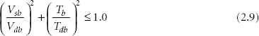
where Vsb = the factored shear force acting on the bolt
Vdb = the design shear capacity
Tb = the factored tensile force acting on the bolt
Tdb = the design tension capacity
2.4.2.7 Other Specifications
- The diameter of the hole should be the nominal diameter of the bolt plus the clearance as given below.

- The minimum pitch: The distance between the centres of the bolts in the direction of stress should not be less than 2.5 times the nominal diameter of the bolt.
- The maximum pitch:
- 32t or 300 mm, whichever is less for the bolts in members including the tacking bolts,
- 16t or 200 mm, whichever is less for the bolts in tension members,
- 12t or 200 mm, whichever is less for the bolts in compression members where t is the thickness of the thinner plate.
- The edge and end distances:
- The minimum edge and end distances from the centre of any hole to the nearest edge of a plate should not be less than 1.7 times the hole diameter for sheared or hand-flame cut edges; and 1.5 times the hole diameter for rolled, machine-flame cut, sawn and planed edges.
- The maximum edge distance from the centre of the hole to the nearest edge should not exceed 12tε, where
 and t is the thickness of the thinner outer plate.
- Tacking bolts:
These are the additional bolts provided other than strength consideration. The maximum pitch of these bolts should be 32t or 300 mm, whichever is less, where t is the thickness of the thinner plate. If the members are exposed to weather, the pitch should not exceed 16 times the thickness of the outside plate or 200 mm, whichever is less.
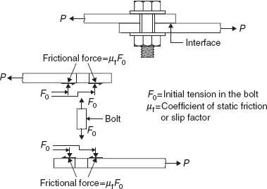
2.4.3 High-strength Bolts
In these bolts, high initial tension is produced which firmly holds the joining parts between the bolt head and the nut. The initial tension produces frictional resistance between the connecting parts which prevents the slip between them. In this type of bolts, proper tightening of the nut on the bolt is important because the frictional resistance produced depends on the initial tension. The force from one member to another is transmitted by friction and the bolts are not subjected to shear or bearing. Such bolts are known as high-strength friction grip (HSFG) bolts. The mechanism of force transfer in a joint with HSFG bolts is shown in Figure 2.18. The use of these bolts reduces the possibility of failure at the net section since the force is transmitted by friction. The connections made using HSFG bolts also have a high fatigue resistance since cyclic loads produce little change in bolt stresses. Hence, the advantage of using HSFG bolts are:
- Rigid joint i.e., no slip between the connecting parts at the working loads.
- High static strength due to high frictional resistance.
- Less load transmission at the net section of the connecting parts.
- No shearing and bearing stresses are produced in the bolts.
- The joints possess high fatigue strength.
- The nuts are prevented from loosening.
Connections using high-strength bolts may be designed
- to develop full frictional resistance at the ultimate load i.e., no slip is permitted at the ultimate load or
- to develop full frictional resistance only at working load i.e., no slip is permitted at the working load but a slip may occur at the ultimate load. When a slip is allowed at the ultimate load, the bolts are subjected to shear and bearing and the specifications in Sec. 2.4.2 are applicable.
2.4.3.1 Design Specifications as per IS800: 2007 and IS4000: 1992
2.4.3.1.1 General Considerations
- High-strength bolts, nuts and washers should confirm to IS 3757:1985, IS 6623:1985 and IS 6649:1985 respectively.
- The property classes of the high-strength bolts are 8.8, 9.8,10.9 and 12.9.
- Standard clearances, edge distances and pitch are the same as in Sec. 2.4.2.7.
- Holes should be provided by drilling only for all friction type joints.
2.4.3.1.2 Slip Resistance
The design frictional force produced by a bolt at the interface of the connecting parts is given by
where Vnf = the nominal frictional capacity produce by a bolt
in which
µf = the coefficient of friction or slip factor, usually 0.55
nc = the number of effective interfaces offering frictional resistance
Kh = 1.0 for standard clearance
γmf = 1.10 for slip resistance designed at a service load
= 1.25 for slip resistance designed at the ultimate load
F0 = the minimum bolt tension (proof load) = Anb f0
Anb = the net tensile stress area of the bolt (Table 2.2)
f0 = the proof stress = 0.7 fub
fub = the ultimate tensile strength of the bolt material
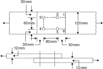
Example 2.4
Determine the ultimate load carrying capacity in tension of the lap joint shown in Figure 2.19 if the bolt threads are outside the shear plane. Use M16 bolts of product grade C and property class 4.6. The yield and ultimate strengths of the flats are 250 MPa and 410MPa, respectively.
Since property class of bolt is 4.6, fub = 4 × 100 = 400 MPa
The diameter of the hole = 16 + 2 = 18 mm
The design strength of the flat due to rupture at the net section,
Tdn = 0.9 An fu/γm1
= 0.9 (120 − 2 × 18) × 12 × 410/1.25
= 2,97,561.6 N
The design bearing strength of the bolt,
Vdpb = Vnpb /γmb = 46, 433.3/1.25 = 37,146.6 N
∴ kb = 0.55
Vnpb = 2.5 kb dt fu = 2.5 × 0.55 × 16 × 12 × 410 = 1,08,240 N
The design bearing strength of the bolt, Vdpb = Vnpb/γmb = 108240/1.25 = 86,592 N
The design strength of the connection in the shear or bearing
= 4 × (Least value of Vdsb and Vdpb)
= 4 × 37146.6 = 1,48,586.4 N
Avg = 2(80 + 30) × 12 = 2640 mm2 (along 1–2–3 and 4–5–6)
Avn = 2(80 + 30–1.5 × 18) × 12 = 1992 mm2 (along 1–2–3 and 4–5–6)
Atg = 60 × 12 = 720 mm2 (along 3–4)
Atn = (60 – 18) × 12 = 504 mm2 (along 3–4)
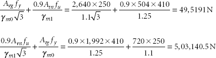
The design strength due to block shear (least of 4,95,191 N and 5,03,140.5 N)
The ultimate load carrying capacity of the joint
Example 2.5
Design a double cover plate butt joint using M24 bolts of product grade C and property class 5.6 to connect two flats of size 350 mm × 16 mm for maximum efficiency. Assume that one shear plane intercepts the threads of the bolts. The yield and ultimate tensile strengths of the flats are 250 MPa and 410 MPa, respectively.
For property class 5.6, the ultimate strength of the bolt material = 5 × 100 = 500 MPa
The total thickness of the cover plates is kept more than the thickness of the flats to be connected. So, the thickness of the flats becomes the least.
The diameter of the bolt hole = 24 + 2 = 26 mm
Since the bolts are in double shear, there are two shear planes. It is given that one shear plane intercepts the threads of bolts. So, nn = 1 and ns = 1.
The design shear strength of the bolt, Vdsb = Vnsb/γmb = 232499/1.25 = 1,85,999 N
∴ kb = 0.513
Vnpb = 2.5 kb dtƒu = 2.5 × 0.513 × 24 × 16 × 410 = 2,01,916.8 N
The design bearing strength of the bolt, Vdpb = Vnpb/γmb = 2,01,916.8/1.25 = 1,61,533.4 N
The design strength of the bolt = Least value of Vdsb and Vdpb = 1,61,533.4 N
The design strength of the flat due to yielding, Tdg = Ag ƒy / γm0
where Ag = the gross sectional area of the flat = 350 × 16 = 5,600 mm2
γm0 = the partial safety factor for failure in tension by yielding = 1.1
∴ Tdg = 5,600 × 250/1.1 = 12,72,727.3 N
To design the connection for maximum efficiency, bolts are provided in a diamond shape. The weakest section for the flats is 1-1 (Figure 2.20) where there is one bolt hole. The design strength of the flat due to rupture at the net section,
The design strength of the flat
The number of the bolts needed
Eight bolts may be provided as shown in Figure 2.20 for maximum efficiency of the connection.
If t1 is the thickness of each cover plate, its design strength due to yielding
For cover plates, 4–4 is the weakest section.
The design strength of the cover plate due to rupture at the net section
Since there are two cover plates,
or t1 = 8 mm
Two cover plates, each 10 mm thick, may be provided.
Example 2.6
Re-do example 2.4 using high-strength bolts of nominal size M16 of the property class 8.8 if (a) no slip is permitted at ultimate load and (b) slip is permitted at ultimate load.
Since the property class of the bolt is 8.8, ƒub = 8 × 100 = 800 MPa
(a) If no slip is permitted at the ultimate load:
Vnf = the nominal frictional capacity produced by a bolt
= μf nc Kh F0 where F0 = Anb f0
= 0.55 × 1 × 1.0 × 157 × (0.7 × 800) (since for a lap joint, nc =1)
= 48,356 N
The design frictional force produced by a bolt
Vdsƒ = Vnsƒ / γmf = 48,356/1.25 = 38,685 N
Since there are 4 bolts, the design frictional force developed in the connection
= 4 × 38,685 = 1,57,740 N
∴ The ultimate load carrying capacity of the joint = 1,57,740 N
(b) If slip is permitted at the ultimate load:
As slip occurs at the ultimate load, the joint is to be designed to shear and bearing as in Example 2.4. It is assumed that the bolt threads are outside the shear plane.
![]() (from Table 2.2, Asb = 201 mm2)
(from Table 2.2, Asb = 201 mm2)
Vdsb = 92,866.5/1.25 = 74,293.2 N
Vnpb = 2.5 × 0.55 × 16 × 12 × 410 = 1,08,240 N
Vdpb = 1,08,240/1.25 = 86,592 N
The design strength of the connection in shear or bearing
Again, the design strength due to rupture at the net section and the design strength due to block shear are the same as in Example 2.4, i.e., 2,97,561.6 N and 4,95,191 N, respectively.
∴ The ultimate load carrying capacity of the joint
Example 2.7
Design a double cover plate butt joint to transmit a working load of 300k N to connect two flats 120 mm wide and 20 mm thick using M16 high-strength bolts of property class 10.9 if (a) slip is not permitted at the working load and (b) slip is not permitted at the ultimate load. The cover plates are 12 mm thick. Assume that one shear plane intercepts the threads of the bolts.
As the property class of bolts is 10.9, fub = 10 × 100 = 1,000 MPa
The diameter of the hole = 16 + 2 = 18 mm
(a) Slip is not permitted at the working load
This means that a slip between the connecting parts may occur at the ultimate load. Therefore, the joint is designed for a no-slip condition at the working load but should be checked for bearing and shear at the ultimate load.
The design frictional force produced by a bolt
The number of bolts needed = 300 × 103/1,09,900 = 2.76
Three bolts are needed for a no-slip condition at the working load.
The joint should be checked for bearing, shear and block shear at the ultimate load.
![]()
Vdsb = Vnsb/γmb = 2,06,727/1.25 = 1,65,382 N
![]()
kb = 0.74
Vnpb = 2.5 × 0.74 × 16 × 20 × 410 = 2,42,720 N
Vdpb = Vnpb/γmb = 2,42,720/1.25 = 1,94,176 N
The design strength of the bolt in shear and bearing = least of 1,65,382, 1,94,176 N
The design strength of 3 bolts at the ultimate load = 3 × 1,65,382 = 4,96,146 N = 496 kN
OK
Check for block shear:
The least of these values 6,64,725 N is greater than 1.5 × 300 = 450 kN.
Hence, 3 bolts may be provided as shown in Figure 2.22(a)
(b) Slip is not permitted at ultimate load
Vnf = 1,20,890 N (same as in (a))
The design frictional force produced by a bolt
Vdsf = Vnsf /γmf = 1,20,890/1.25 = 96712 N
The number of bolts needed = 1.5 × 300 × 103/96,712 = 4.5
Five bolts may be provided as in Figure 2.22(b).
Example 2.8
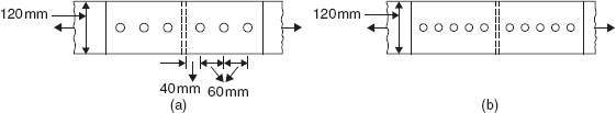
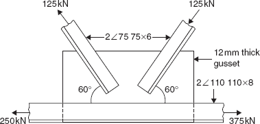
The lower chord joint of a roof truss is with a continuous chord member. Design and detail the joint using M20 bolts of the product grade C and the property class 4.6. fy = 250 MPa and fu = 410 MPa.
Since the property class of bolts is 4.6, fub = 400 MPa
As the bolts are subjected to double shear, it is assumed that one shear plane intercepts the threads.
Taking the end distance, e = 40 mm and the pitch, p = 60 mm
kb = 0.606
Vnpb = 2.5kb dtfu = 2.5 × 0.606 × 20 × 12 × 410 = 1,49,076 N
Vdpb = 1,49,076/1.25 = 1,19,261 N
∴ The design strength of the bolt = 1,03,314 N
The number of bolts required to connect 2 ∠ 75 75 × 6 to gusset = ![]() = 1.8
= 1.8
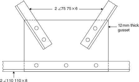
Two bolts may be provided as shown in Figure 2.24.
As the cord member 2 ∠110 110 × 8 is continuous, bolts connecting this member with the gusset are designed for the resultant force equal to 125 cos 60° + 125 cos 60°, i.e., 125 kN.
Again, the number of bolts required will be 1.8 (as above).
Three bolts may be provided as shown in Figure 2.24.
Problems
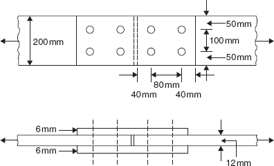
- Two 12 mm thick steel flats are spliced by two 6 mm thick plates with four M16 bolts of the product grade C and the property class 4.6 (Figure 2.25). Determine the ultimate design load carrying capacity of the connection. fy = 250 MPa and fu = 410 MPa.
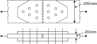
- Determine the ultimate design capacity of the connection shown in Figure 2.26 in tension. M20 bolts of the product grade C and the property class 5.6 are used. Also, find the thickness of the cover plates. fy = 250 MPa and fu = 410 MPa.
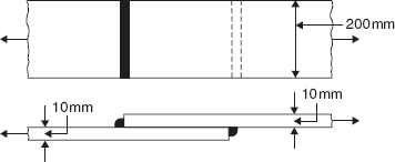
- Determine the size of fillet welds needed for the strength of the plates in tension (Figure 2.27). fy = 250 MPa and fu = 410 MPa.
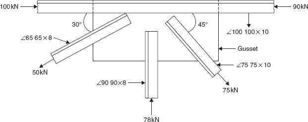
- Design a welded connection for the members at a joint of truss shown in Figure 2.28. fy = 250 MPa and fu = 410 MPa. The forces shown are at the service load.
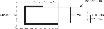
- Find the lengths of the fillet welds shown in Figure 2.29 to connect ∠ 100 100 × 10 to a gusset of 12 mm thickness. fy = 250 MPa and fu = 410 MPa.
- Design and detail a tension splice to connect 300 mm × 12 mm flat with 300 mm × 16 mm flat using two cover plates to carry a tension of 400 kN. Use M20 high-strength bolts of the property class 8.8 if (a) no slip is permitted at the ultimate load and (b) slip is permitted at the ultimate load. fy = 250 MPa and fu = 410 MPa.