13
Composite Construction
13.1 Introduction
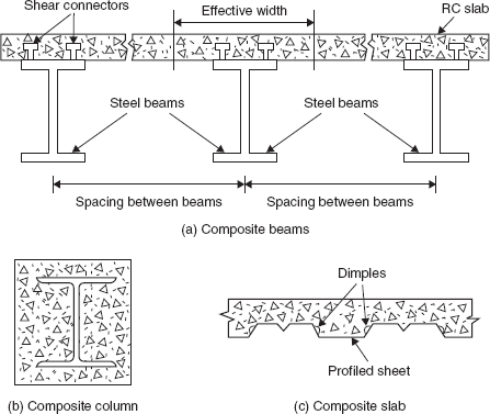
Composite construction means structures constructed using both structural steel and concrete by establishing the composite action between the two. The variety of structural elements constructed in this manner are composite beams, composite columns, and composite slabs (Figure 13.1). A portion of reinforced concrete slab supported on steel beam with a connection between the two so that they act as one section is known as a composite beam. In the case of composite columns, steel sections are encased in concrete columns. A composite slab may also be constructed using profiled sheet decking. In this introductory chapter on composite construction, only the design of composite beams is considered.
13.2 Composite Beam
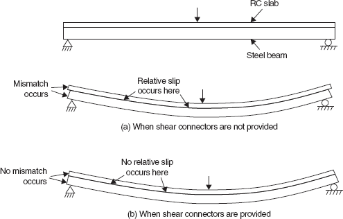
Reinforced concrete slabs are supported on steel beams in industrial buildings and bridges. In the conventional construction, there may be no connection between the concrete slab and the steel beam which makes the two elements deform separately, and a relative slip occurs between the two when subjected to load (Figure 13.2(a)). The entire load is carried by each member. If sufficient shear connection is provided between the two components, no relative slip occurs between the two components and they act as one integral section. The entire load is now carried by both the components together, which means that they share the entire load. This helps to economize the materials. Thus, the portion of RC slab and the steel beam acts as a composite beam (Figure 13.2(b)). The connection between the slab and the steel beam is provided by what are known as shear connectors. The connectors are welded to the top flange of the steel beam and are embedded in the concrete slab. The popularly used shear connectors are round-headed studs, which are electrically fused to the steel flange by a light portable stud gun.
The effective width of the concrete slab, which acts as a composite beam together with the steel beam, is as per IS 456:2000 Plain and reinforced concrete—Code of practice. It is given by
where l0 is the effective span of the beam, bf is the width of the flange of the steel beam and ds is the thickness of the concrete slab. In no case should it be greater than the sum of half of the centre-to-centre spacing on either side of the beam.
IS 11384:1985 Code of practice for composite construction in structural steel and concrete deals with the design and construction of steel–concrete composite beams. The Code is based on the Limit state design concept. The design of the composite beam as per IS 11384:1985 is explained in the following sections.
13.3 Methods of Construction
After shear connectors are welded to the flanges of steel beams, concreting of slabs may be done in two ways: by using props below the steel beams, known as propped construction or by not using any props, known as unpropped construction. In the unpropped construction, the steel beam alone has to carry the construction load of shuttering, machinery and workers, the weight of the wet concrete and its own weight. Only the live load is carried by the composite action. Hence, two cases of design are to be considered: (i) During construction, the steel beam alone has to be designed to carry the relevant loads and (ii) after construction, when the actual live load acts, composite beam design should be done. In the propped construction, both the dead load and the live load are carried by composite action. When props are used, they should be kept in place until the in-situ concrete attains a characteristic strength equal to at least twice the stress to which the concrete may be subjected shortly after the removal of the props.
13.4 Limit State of Collapse
13.4.1 Limit State of Collapse: Flexure
The design for the limit state of collapse in flexure is based on the following assumptions:
- Plane sections normal to the axis remain plane after bending.
- The maximum strain in concrete at the outermost compression fibre is taken as 0.0035.
- The stress–strain curves for concrete and steel are as in IS 456.
- The tensile strength of the concrete is ignored.
The position of the plastic neutral axis and the ultimate moment of resistance may be determined as follows. In a section of homogeneous material, the plastic neutral axis coincides with the equal area axis of the section. The same concept can be used in the case of composite beams also, provided the steel area is transformed into an equivalent concrete area by multiplying it with the stress ratio
where fy is the yield strength of steel and fck is the characteristic strength of concrete in 28 days.
Case (i): Plastic neutral axis within the concrete slab (Figure 13.3)
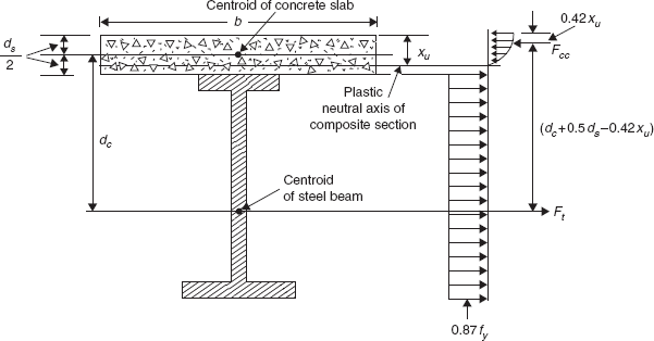
This happens when bds ≥ aAs, where As is the area of the steel section.
For force equilibrium,
i.e.
or
Taking moments about a point on the line of action of Fcc, the ultimate moment of resistance of the composite section is given by
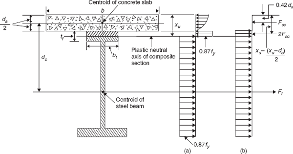
Case (ii): Plastic neutral axis is within the top flange of the steel beam (Figure 13.4)
i.e.
This happens when bds < aAs < (bds + 2aAf ), where Af is the area of the flange of the steel beam.
The actual stress distribution at collapse is shown in Figure 13.4(a). The derivation of formulae will be simplified by considering an equivalent stress distribution as shown in Figure 13.4(b).
Thus, the steel beam is assumed to yield in tension through its full depth, the total equivalent force Ft being balanced by the compressive force Fcc in the concrete plus twice the compressive force Fsc in the flange of the steel beam above the plastic neutral axis.
where Asc is the area of the flange of the steel beam in compression above the plastic neutral axis.
For force equilibrium,
From Equations (13.5) to (13.8),
From Equations (13.9) and (13.10)
Taking moments about a point on the line of action of Fcc, the ultimate moment of resistance of the composite section is given by
or
Case (iii): Plastic neutral axis is within the web of the steel beam (Figure 13.5)
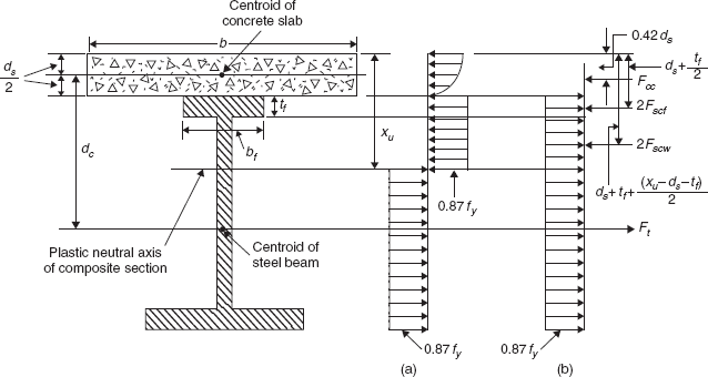
i.e.
This occurs if
In this case, Equations (13.5) and (13.6) are still valid. Twice the compression forces in the upper flange and in the part of the web of the steel beam are given by
For force equilibrium,
From Equations (13.5), (13.6), (13.13)–(13.15)
Taking moments about a point on the line of action of Fcc, the ultimate moment of resistance of the composite section is given by
Substituting the values of Ft, 2Fscf and 2Fscw from Equations (13.5), (13.13) and (13.14) and upon simplification
13.4.2 Limit State of Collapse: Horizontal Shear
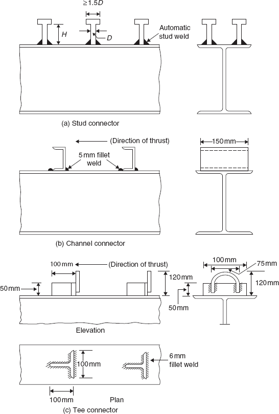
Mechanical shear connectors should be provided to transmit the horizontal shear between the steel beam and the concrete slab. The number of shear connectors provided should be such that they resist the maximum value of the horizontal shear force to be transmitted at collapse between points of maximum and zero moment. The maximum value of the horizontal shear force should be equal to the total compressive force in concrete
The design strength of various types of shear connectors (Figure 13.6) for different grades of concrete are given in Table 13.1. The number of transverse sections where shear connectors are to be provided between the locations of maximum and minimum bending moments is calculated from
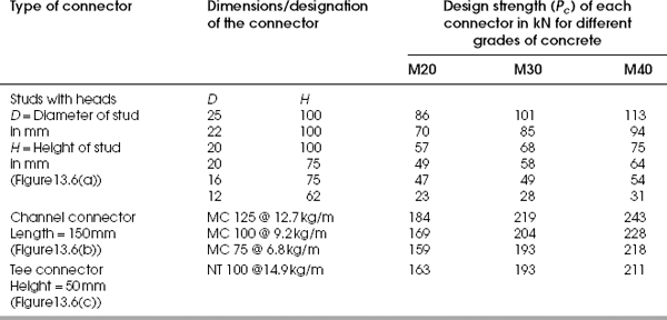
where Pc is the design strength of one shear connector obtained from Table 13.1, and Nc is the number of shear connectors provided at a transverse section. Generally, shear connectors are uniformly spaced along the length of the beam, and the spacing between the transverse sections is calculated from
where Lc is the distance between the locations of maximum and minimum bending moments in a composite beam. The spacing should neither be greater than four times the slab thickness nor greater than 600 mm.
13.4.3 Limit State of Collapse: Vertical Separation of Concrete Slab
This is usually taken care of by proper detailing of the shear connectors as shown in Figure 13.6. The overall height of the connector should neither be less than 50 mm nor project less than 25 mm into the compression zone of the concrete slab.
13.5 Limit States of Serviceability: Deflection
In this case the beam is analysed using the elastic theory adopting a modular ratio of 15 for a live load and 30 for a dead load and neglecting the tensile stress in concrete. The deflection should not exceed span/325.
Example 13.1
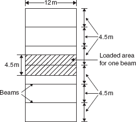
Design a simply supported composite beam to support the slab of a building 12 m × 27 m with beams spaced at 4.5 m centre to centre. The thickness of the concrete slab is 125 mm. Consider a floor finish load of 0.5 kN/m2 and a live load of 3 kN/m2. Grade of concrete is M20 and the yield strength of the material of the steel beam is 250 MPa. Assume that the propped method of construction will be used.
Span of the beam, l0 = 12 m
Thickness of the slab, ds = 125 mm
Self-weight of the slab = 0.125 × 4.5 × 25 = 14.1 kN/m
Weight of the floor finish = 0.5 × 4.5 = 2.25 kN/m
Self-weight of the steel beam = 1.0 kN/m (assumed)
Live load = 4.5 × 3.0 = 13.5 kN/m
Total intensity of the load = 14.1 + 2.25 + 1.0 + 13.5
= 30.85 ≈ 31 kN/m
Factored Load = 1.5 × 31 = 46.5 kN/m
Design of steel beam
Maximum bending moment ![]()
Plastic section modulus ![]()
Because of composite action, the steel section itself need not have this much section modulus.
Try MB500. From Appendix A, plastic section modulus, Zp = 2,074.7 cm3; sectional area, As = 11,100 mm2; bf = 180 mm; tf = 19.3 mm; tw = 11.2 mm.
The effective width of the concrete slab,
Location of plastic neutral axis:
xu = aAs/b = 30.21 × 11,100/2,930 = 114.4 mm
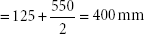
dc = (Depth of steel beam + Thickness of concrete slab)/2
= (500 + 125)/2 = 312.5 mm
Mu = 0.87Asfy (dc + 0.5ds − 0.42xu)
= 0.87 × 11,100 × 250 (312.5 + 0.5 × 125 − 0.42 × 114.4)
= 789.3 kNm < 837 kNm Not safe
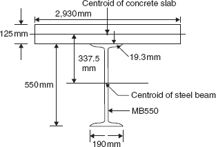
Try MB550. From Appendix A,
As = 1,32,00 mm2, bf = 190 mm, tf = 19.3 mm, tw = 11.2 mm
aAs = 30.21 × 13,200 = 3,98,772 mm2 > bds
bds + 2aAf = 3,66,250 + 2 × 30.21 × (190 × 19.3) = 5,87,810.1 mm2
bds < aAs < (bds + 2aAf)
∴ Plastic neutral axis lies in the top flange of the I section.
Mu = 0.87fy [As(dc + 0.08ds) − bf (xu − ds)(xu + 0.16ds)]
= 0.87 × 250 [13,200(337.5 + 0.08 × 125) − 190(127.8 − 125)(127.8 + 0.16 × 125)]
= 980.6 kNm > 837 kNm
Design of shear connectors
Using head-type stud connectors with D = 20 mm and H = 75 mm, design the strength of one stud = 49 kN for M20 grade concrete (from Table 13.1).
The number of transverse sections where shear connectors are to be provided between the locations of maximum and minimum bending moments:
Spacing between the transverse sections,
where Lc = half span = 6 m. A spacing of 200 mm may be provided.
Check for deflection
Intensity of the dead load, wd = 14.1 + 2.25 + 1.0 = 17.35 kN/m
Intensity of the live load, wl = 13.5 kN/m
- Deflection due to the dead load (modular ratio, m = 30)
Ac = area of the concrete slab = 2,930 × 125 = 3,66,250 mm2
As = area of the steel section = 13,200 mm2
yc = distance from the top concrete slab to its centroid = 125/2 = 62.5 mm
ys = distance from the top concrete slab to the centroid of the steel section
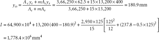
Depth of neutral axis of the transformed section from the top of the concrete slab

Moment of inertia of the transformed section

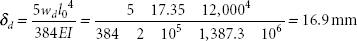
Deflection due to the dead load,
- Deflection due to the live load (modular ratio, m = 15)
Deflection due to the live load,
Total deflection = δd + δd = 16.9 + 10.25 = 27.15 mmLimiting defl ection = l0 /325 = 12,000/325 = 36.9 mm > 27.15 mmOK
Problems
- Select a wide flange beam (WB) to resist an ultimate bending moment of 1,200 kNm. The effective width of the concrete slab is 2.0 m and its thickness is 0.15 m. Use M30 grade concrete and E250 grade steel. Assume that shear connection is provided between the steel beam and the concrete slab.
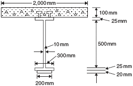
- Determine the ultimate moment of resistance of the composite beam shown in Figure 13.9. Use M20 grade concrete and E250 grade steel.
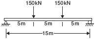
- Design a composite beam for the data shown in Figure 13.10. The effective width of the concrete slab is 2.0 m and its thickness is 0.15 m. Use M30 grade concrete and E250 grade steel. Also, design suitable shear connectors and determine their spacing in different segments of the beam as per IS11384:1985. Two concentrated live loads, each 150 kN, act as shown in the figure in addition to the dead load.
- Re-design Example 13.1 assuming that the unpropped type of construction will be used. The load due to shuttering, machinery and workers may be suitably considered.