4
Compression Members
4.1 Introduction
A member which carries an axial compression is known as a compression member. It is also called a strut. A compression member may be called – short or long depending on the slenderness ratio (KL/r), where KL is the effective length and r is the least radius of gyration of the cross section. For small values of KL/r, a compression member undergoes only simple compression (Figure 4.1(a)). Such a compression member is known as a short column. For large values of KL/r, a compression member undergoes buckling i.e., side way deflection (Figure 4.1(b)). Such a compression member is known as a long column.
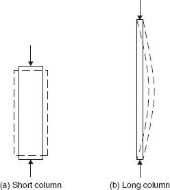
In the case of a long column, as the load is gradually increased, a condition is reached in which the equilibrium of the column becomes neutral. That is, at that load if the column (which is in a straight position) is slightly disturbed, the column gets deflected and remains in a deflected position (Figure 4.1(b)). The load corresponding to this equilibrium state of the column is known as a critical load. Up to this load, a column remains straight and in stable equilibrium, which is the useful range of a column. Therefore, a short column fails by crushing or yielding whereas a long column fails by buckling i.e., the loss of stable equilibrium state. The knowledge of buckling or the elastic stability of the compression members is essential for the design of compression members. The basis for the design of long columns is Euler's buckling theory.
4.2 Euler's Buckling Theory
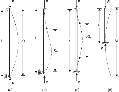
Consider an initially straight prismatic long column with both the ends pinned subjected to an axial compression P as shown in Figure 4.2(a). The critical load of the column is given by
where E = the modulus of the elasticity of the material of the column,
I = the least moment of inertia of the cross section of the column,
L = the length of the column between the supports.
Dividing both the sides of the Equation 4.1 by the cross sectional area of the column, it may be written in the form
where r is the least radius of gyration of the cross section of the column and L/r is known as slenderness ratio.
The Equation 4.2 may be written in a general form to account for different end conditions.
i.e.,
where KL is known as the effective length of the column in which K is a factor. The values of K for the four basic end conditions are given in Table 4.1.
Table 4.1 The effective length factor, K
| End conditions of column | K |
|---|---|
| Both ends pinned (Figure 4.2(a)) | 1.0 |
| One end fixed, other end pinned (Figure 4.2(b)) | 0.707 |
| Both ends fixed (Figure 4.2(c)) | 0.5 |
| One end fixed, other end free | 2.0 |
4.3 Behaviour of Real Columns
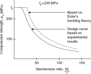
Euler's buckling theory is valid for initially straight long columns, the material of which obeys Hooks law (i.e., linearly elastic). Hence, σcr should be less than or equal to the proportional limit of the material. The compressive strength of real columns is affected by initial imperfections, the eccentricity of load, residual stresses and the lack of a definite yield point for the material of the column. A number of tests conducted on real columns have enabled us to arrive at a design curve shown in Figure 4.3. For the structural design of columns, Euler's buckling theory is modified to account for the behaviour of real columns.
4.4 Types of Sections
As the compressive strength σc decreases with the increase in the slenderness ratio, a section for the compression member should be such that it has the maximum moment of inertia for the same sectional area. It is preferable that the section has the same moment of inertia for both the principal axes. Some of the sections used for compression members are shown in Figure 4.4.
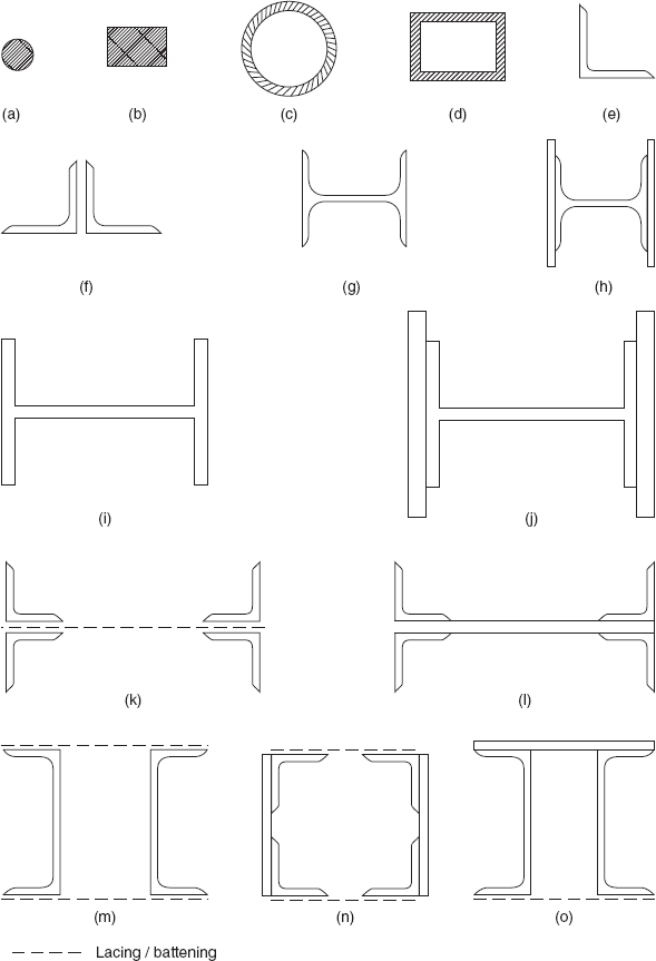
If a compression member is free to buckle in any direction, a solid circular or tubular section (Figure 4.4(a, c)) may be used. A solid circular section has a much smaller radius of gyration and hence it is not efficient. Tubular sections are widely used in roof trusses and towers. Again, a hallow rectangular section (Figure 4.4(d)) is more efficient than a solid rectangular section (Figure 4.4(b)).
Nowadays, a single angle (Figure 4.4(e)) is used as the compression member mostly in towers. It is also used as a bracing member in plate girder bridges and in large built-up columns. Since it is connected to the gusset by one leg only, it is affected by shear-lag. Instead of a single section, a double angle section (Figure 4.4(f)) may be used. The double angle sections should be tack bolted or tack welded at suitable spacing so that the two angles act as one section. The spacing should be such that each angle is safe against buckling between two consecutive tack bolts or welds.
Single SC/HB sections (Figure 4.4(g)) or SC/HB sections with plates (Figure 4.4(h)) are used as a light column in buildings. Alternatively, parallel flange column sections (WPB) without or with plates may be used (Figure 4.4(i, j)). Larger building columns may be made with two SC/HB/WPB sections using lacing or battening. Four angle sections (Figure 4.4(k, l)) with lacing or web plates may also be used. A section consisting of two channel sections (Figure 4.4(m)) is used as a web compression member in truss girder bridges. Four angles arranged in a box using plates or lacing or battening (Figure 4.4(n)) are sometimes used as long members carrying small loads. In compression chord members in trusses, a top cover plate is used with two channel sections (Figure 4.4(o)). Lacing or battening is provided at the bottom.
4.5 Design of Columns as per IS 800:2007
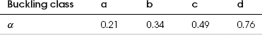
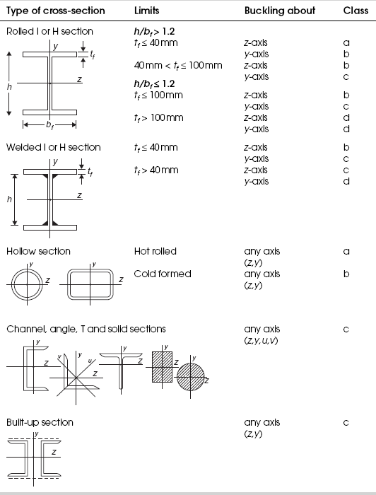
As the buckling strength of columns is affected by residual stresses, initial bow and accidental eccentricities of load, IS 800:2007 defined buckling classes a, b, c, d depending on the imperfection factor. The values of the imperfection factor are given in Table 4.2. The classification of the different sections into buckling classes a, b, c, d is given in Table 4.3.
The factored design compression (P) in the members should satisfy
where
in which Ae = the effective sectional area,
fcd = the design compressive stress.
The design compressive stress fcd of axially loaded compression members is given by
where
KL/r = the effective slenderness ratio,
α = the imperfection factor as given in Table 4.2,
γm0 = the partial safety factor = 1.25.
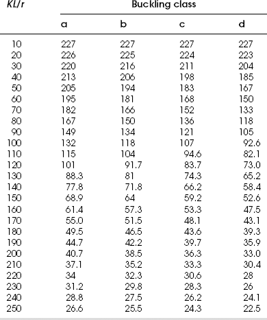
Values of fcd obtained using the above formula for E250 grade steel are given in Table 4.4 for different buckling classes.
4.5.1 Single Angle Strut
If a single is loaded in compression through one leg, it is subjected to flexural torsional buckling. In such a case, the design strength Pd may be evaluated using the non-dimensional equivalent slenderness ratio λe for λ in the expressions for χ and ϕ (Equations 4.7 and 4.8).
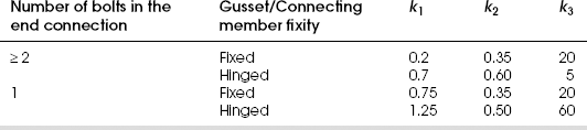
where k1, k2 and k3 are constants which depend on the end conditions (Table 4.5)
and
in which
L = the centre to centre length between the end connections
rv = the radius of gyration about minor axis (v)
b1, b2 = the widths of two legs of the angle
t = the thickness of the angle

fy = The yield strength of the steel
E = Young's modulus of steel = 2 × 10⁵ MPa
4.5.2 Discontinuous Double Angle Struts
4.5.2.1 Back to Back to the Same Side of Gusset
If angles are connected back to back to the same side of a gusset by one or more bolts in each angle or by equivalent welding, should be designed as per Sec. 4.5.1 considering them as two single angles loaded in compression through one leg. However, they should be tack bolted or welded as described in Sec. 4.5.4.
4.5.2.2 Back to Back to Both Sides of Gusset
If angles are connected to both sides of a gusset by not less than two bolts or equivalent welding, the load may be regarded as applied axially and their design strength may be obtained using Equations 4.5 to 4.10 provided they are tack bolted and welded as described in Sec. 4.5.4. The effective length KL in the plane of end gusset should be taken as between 0.7 and 0.85 times the distance between the intersections depending on the degree of the end restraint. The effective length KL in the plane perpendicular to that of the end gusset should be equal to the distance between the centres of intersections.
4.5.3 Continuous Double Angle Struts
Double angle continuous struts, viz, back to back to the same side of a gusset or back to back to both sides of a gusset, may be considered as axially loaded and their design strength may be calculated using Equations 4.5 to 4.10 provided they are tack bolted or welded as described in Sec. 4.5.4.
4.5.4 Other Design Specifications
- The effective length KL is obtained from the actual length L of the compression member considering the end conditions. The actual length of the compression member L should be taken as the length from the centre to the centre of the intersections with the supporting members. In the case of a column with one end fixed and the other end free, the free standing length from the centre of the support should be taken as the actual length L.
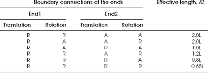
- If the boundary conditions at the ends of the compression member in the plane of buckling can be assessed, the effective length KL can be obtained from Table 4.6. Otherwise, the effective length KL may be calculated referring to the Annexure-D in IS 800:2007.
- In the case of trusses and braced frames, the effective length KL of a compression member, in the plane of truss or braced frame, lies between 0.7 to 1.0 times the distance between the centres of connections depending on the degree of the end restraint; in the perpendicular plane, KL should be taken as the distance between centres of connections.
- The maximum slenderness ratio
- A member carrying a compression resulting from dead and imposed loads: 180
- A tension member in which a reversal of stress (i.e., compression) occurs due to loads other than wind and seismic forces: 180
- A member subjected to compression forces resulting only from a combination of wind/earthquake forces, provided the deformation of such member does not adversely affect the stress in any part of the structure: 250
- Compression members composed of two angles, channels or tees, back to back in contact or separated by a small distance should be connected together by bolting or welding along their length (known as tack bolting or tack welding) so that the maximum slenderness ratio of each component of column between consecutive connections is not greater than 40 or 0.6 times the maximum slenderness ratio of the strut as a whole, whichever is less. In any case, the spacing of these bolts/welds should not exceed 600 mm. The ends of such compression member should be connected to a gusset or a supporting member with at least two bolts or equivalent welding.
- Where the members are separated back-to-back, the tack bolts should pass through solid washers or packings in between the members. In the tack welding, solid packings should be used unless the members are sufficiently close together to permit welding.
4.6 Validity of Design Strength Calculations
The design strength of columns presented in Sec. 4.5 are valid for plastic (Class 1), compact (Class 2), semi-compact (Class 3) as defined in Table 1.8 of Chapter 1 in which the plate elements of the section do not buckle locally before the yielding or buckling of the entire column. If a section is slender (Class 4), the reduced widths of the plate elements of the section are to be considered deducting excess widths except those corresponding to the limiting widths for a semi-compact (Class 3) section for the calculation of the effective sectional area and the moments of inertia. Such sections are separately considered in Chapter 12.
4.7 Design Procedure
The designing of compression member means arriving at a suitable section given the design load to be carried and the length and type of the end connection. Unlike tension members, the designing of compression members is not straight forward since the design compressive stress fcd depends on KL/r which is not known initially. Hence, it involves the trial and error procedure. First, an average value for fcd is assumed, from which the required area of the cross section is calculated. Then, a trial section is selected and its design load carrying capacity is ascertained. If this design load carrying capacity is almost equal to or slightly greater than the design load to be carried (known as the design condition), then the trial section is all right. Otherwise, another section is to be selected depending on the design load carrying capacity of the trial section and the procedure is repeated till the design condition is reached.
Example 4.1
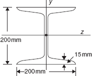
SC 200 is used as a column (Figure 4.5). The column is laterally supported in the plane of the major axis at the height of 3.5 m and in the plane of the minor axis at the height of 2.5 m. Both the ends may be assumed as hinged. What is the design load carrying capacity of the column? The grade of the steel is E250.
The effective length of the column in the plane of the major axis, KLz = 3.5 m
The effective length of the column in the plane of the minor axis, KLy = 2.5 m
From Appendix A, sectional properties: rz = 84.8 mm, ry = 44.6 mm, A = 7,680 mm2
The buckling class of the section: h/bf = 200/200 = 1 < 1.2 and tf = 15 mm < 100 mm
From Table 4.3, the buckling class about z-axis is ‘b’ and the buckling class about y-axis is ‘c’.
From Table 4.4, for buckling class ‘b’ and KL/r = 41.3, fcd = 204.4 N/mm2
for buckling class ‘c’ and KL/r = 56.05, fcd = 173.9 N/mm2
∴ The design load carrying capacity = 7,680 × 173.9 = 1,335.5 kN
Example 4.2
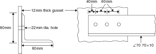
Determine the design load carrying capacity of a single discontinuous ∠ 50 50 × 5 (Figure 4.6) which is used as a compression member in a roof truss if it is connected to a gusset by two bolts. The centre to centre distance between the end connections is 1.5 m. The grade of the steel is E250.
From Appendix A, A = 479 mm2 and rv = 9.7 mm
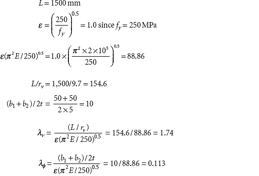
Since the end connection is done by 2 bolts, from Table 4.5,
The imperfection factor, α = 0.49 since the buckling class of the angle is ‘c’
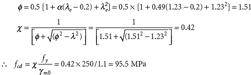
The design load carrying capacity = 479 × 95.5 = 45,745 N
Example 4.3
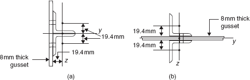
Calculate the design load carrying capacity in compression of a discontinuous strut 2.5 m long (the centre to centre distance between the end connections) consisting of two ∠ 70 70 × 6 in the following cases:
- Connected to the same side of a gusset by more than one bolt in each angle.
- Connected to both sides of 8 mm thick gusset by two bolts. The grade of the steel is E250.
The sectional properties of ∠ 70 70 × 6 (from Appendix A):
A = 806 mm2, rz = ry = 21.4 mm, rv = 13.6 mm, Cz = Cy = 19.4 mm, Iz = Iy = 36.8 × 104 mm4
(i) 2 ∠ 70 70 × 6 connected to same side of gusset (Figure 4.7(a))
Assuming that the gusset is fixed and for more than one bolt in each angle,
The imperfection factor, α = 0.49 since the buckling class of angles is ‘c’
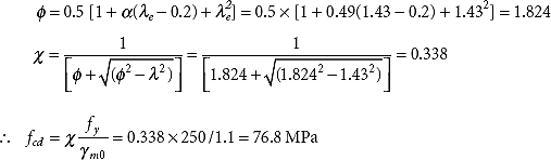
The design load carrying capacity = 2 × 806 × 76.8 = 1,23,801.6 N
(ii) 2 ∠ 70 70 × 6 connected to both sidse of gusset (Figure 4.7(b))
Since the angles are connected to gusset by two bolts,
the effective length in the plane of gusset, KLz = 0.85 × 2500 = 2,125 mm
the effective length in the perpendicular plane, KLy = 2,500 mm
rz of the double angle section = 21.4 mm (same as rz of ∠ 70 70 × 6)
Iy of the double angle section = 2[36.8 × 10⁴ + 806 × (19.4 + 0.4)2] = 13,67,968.5 mm4
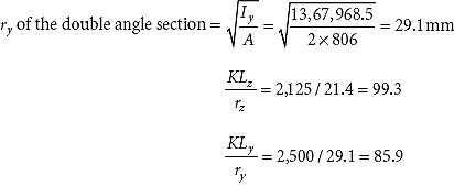
From Table 4.4, for buckling class c, for ![]()
The design load carrying capacity = 2 × 806 × 108 = 1,74,096 N
Example 4.4
Design a single angle section to carry a compression of 100 kN. The centre to centre distance between the end connections is 2 m. Assume that the end connection is done by at least two bolts. Design the end connection also. The grade of the steel is E250.
The angle belongs to the buckling class ‘c’ (Table 4.3). fcd varies from 227 MPa to 24.3 MPa (Table 4.4) depending on KL/r.
The required area of section ![]()
∠ 80 80 × 8 may be tried.
From Appendix A, A = 1,220 mm2, rz = ry = 24.4 mm, ru = 30.8 mm, rv = 15.5 mm
ε = 1.0 and ε (π2 E/250)0.5 = 88.86 as in Example 4.2
λv = 129/88.86 = 1.45 and λφ = 10/88.86 = 0.1125
Assuming that the gusset is fixed and for two bolts in the end connection,
k1 = 0.20, k2 = 0.35 and k3 = 20 (from Table 4.5)
λe = (k1 + k2λv2 + k2λφ2)0.5 = (0.20 + 0.35 × 1.452 + 20 × 0.11252)0.5 = 1.09
The imperfection factor, α = 0.49 since the buckling class of the angles is ‘c’
φ = 0.5 [1 + α(λe − 0.2) + ![]() ] = 0.5 × [1 + 0.49(1.09 − 0.2) + 1.092] = 1.3121
] = 0.5 × [1 + 0.49(1.09 − 0.2) + 1.092] = 1.3121
![]()
∴ fcd =  = 0.4896 × 250/1.1 111.3MPa
The design load carrying capacity = 1,220 × 111.3 = 1,35,750 N < 1.5 × 100 kN. As the load carrying capacity is less than the load to be carried, a higher section
∠ 80 80 × 10 is tried.
The sectional properties: a = 1,500 mm2, rx = ry =24.1 mm, ru = 30.4 mm, rv = 15.5 mm
![]()
λv = 129/88.86 = 1.45 and λϕ = 8/88.86 = 0.09
λe = (0.20 + 0.35 × 1.452 + 20 × 0.092)0.5 = 1.048
ϕ = 0.5 × [1 + 0.49(1.048 − 0.2) + 1.0482] = 1.2569
![]()
∴ fcd = 0.5126 × 250/1.1 = 116.5 MPa
The design load carrying capacity = 1,500 × 116.5 = 1,74,750 N > 1.5 × 100 kN OK
Design of the end connection
Using M20 bolts of product grade C and property class 4.6,
![]()
(for shear plane out of bolt threads)
Vdsb = 72,552/1.25 = 58,041.6 N
Vnpb = 2.5 kb dtfu = 2.5 × 0.606 × 20 × 10 × 410 = 1,24,230 N
Vdpb = 1,24,230/1.25 = 99,384 N
Number of bolts = 1.5 × 100 × 103/58,041.6 = 2.58
Three bolts may be provided as shown in Figure 4.8.
Example 4.5
Re-do Example 4.4 using a tubular section. The grade of the steel is E250.
Assuming that a welded connection is provided at the ends, KL = 0.85 × 2,000 = 1,700 mm.
For the required sectional area of 1,250 mm2 (as in Example 4.4), a tubular section with the following data may be tried. From Appendix A,
The tubular section belongs to the buckling class ‘a’ (from Table 4.3).
From Table 4.4, fcd = 205.5 N/mm2
The design load carrying capacity = 1,240 × 205.5 = 2,54,820 N >> 1.5 × 100 × 103 N
As the design load carrying capacity is much more than the design load to be carried, a smaller section is tried. Again, from Appendix A,
From Table 4.3, fcd = 185.9 N/mm2
The design load carrying capacity = 1,010 × 185.9 = 1,87,759 N > 1.5 × 100 × 103 N
OK
The end connection is done using the fillet weld by pressing the ends of the tube to an elliptical shape (as shown in Figure 3.8).
Length of the weld = perimeter of the tube = π × 76.1 = 239 mm
The design shear strength of the weld,
A 5 mm size fillet weld may be provided.
Example 4.6
Re-do Example 4.4 using a square hollow section. The grade of the steel is E250.
Again, KL = 1,700 mm
For the required sectional area of 1,250 mm2 (as in Example 4.4), 75 mm × 75 mm × 4.9 mm, the square hollow section may be tried from Appendix E.
Sectional area, A = 1,312 mm2
Radius of gyration, r = 28.3 mm
The hollow section belongs to the buckling class ‘a’ (from Table 4.2).
The design load carrying capacity = 1,312 × 195 = 256 kN >> 1.5 × 100 kN
A smaller section 72 mm × 72 mm × 4 mm may be tried.
A = 1,047 mm2, r = 27.5 mm
![]()
Again, from Table 4.4, fcd = 192 MPa.
The design load carrying capacity = 1,047 × 192 = 201 kN > 1.5 × 100 kN
OK
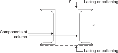
4.8 Built-up Compression Members
For columns with very large unsupported lengths and subjected to heavier loads, single sections like angles, channels, H sections, tubes are not suitable. In such cases, it is very effective to use two or more of these sections separated by a distance and connected by a lateral system (Figure 4.9). The lateral systems commonly used are lacing (also known as latticing) or battening. The spacing of lacing or battening along the length of the column should be such that the individual components ( sections) of the column do not buckle. It is preferable that the failure of the component of the column should be by yielding rather than by buckling. As per Table 4.3, the buckling class of built-up compression members is ‘c ’.
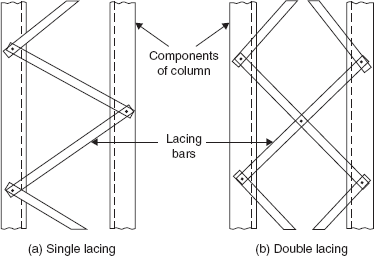
4.8.1 Lacing
Lacing is the most common type of lateral system that is used in built-up columns. The simplest form of lacing is known as single lacing, which is shown in Figure 4.10(a). Sometimes, double lacing is preferred (Figure 4.10(b)). Lacing bars are connected to the components of the column using welding or bolts. The connection is designed to transfer only the axial forces in the lacing bars to the main components and hence, it is not moment resistant. At the ends of the laced column, tie plates (battens) are provided.
Lacing is designed for shear force (V) in columns. The shear force may be due to incidental eccentricity of the applied axial load, moments or lateral forces acting on the column and erection stresses. In a column with single lacing (Figure 4.11), the axial force (F) in the single lacing bar is given by
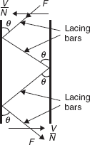
where N is the number of the planes of the lacing.
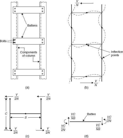
4.8.2 Battening
Battening consists of the provision of the battens along the length of a column (Figure 4.12(a)). These are rigidly connected to the components of a column and hence are subjected to shear force and bending moments. Inflection points are assumed at the mid-points of battens and the components of a column as shown in Figure 4.12(b). From Figures 4.12(c) and 4.12(d), it is seen that a batten is subjected to end moments VC / 2N and shear forces VC / NS where N is the number of planes of battening.
4.8.3 Design Specifications for Lacing as per IS 800:2007
- It is preferable that the radius of gyration of the built-up column about the centroidal axis perpendicular to the plane of lacing (ry) is not less than the radius of the gyration about the centroidal axis in the plane of lacing (rz).
- The effective slenderness ratio of the laced column should be taken as 1.05 times the actual maximum slenderness ratio to account for shear deformation.
- Lacing should be designed to resist a total shear force (V) of 2.5% of the axial force in the column which is equally shared by all transverse lacing systems. This is due to the incidental eccentricity of the axial load only.
- The slenderness ratio of lacing bars should not exceed 145. In bolted construction, the effective length of lacing bars should be taken as the length between the inner end bolts of the bars and as 0.7 times this length for double lacing if it is effectively bolted at the intersection. In welded construction, the effective length of the lacing bar shall be 0.7 times the distance between the inner ends of welds connecting the lacing bars to the components.
- If lacing bars are connected to components of the column by bolts, the minimum width of the lacing bars should be 3 times the nominal diameter of the bolt.
- The thickness of lacing bar should be greater than
 of the length between the inner end bolts or welds for single lacing;
  of the length between the inner end bolts or welds for double lacing.
 - The angle of inclination of lacing bars (θ) may be 40° to 70° to the axis of compression member.
- The spacing of lacing bars should be such that the maximum slenderness ratio of the lesser component of the column between consecutive connections is not greater than 50 or 0.7 times the maximum slenderness ratio of the column as a whole, whichever is less.
- The bolting or welding of lacing bars to the components of the column should be sufficient to transmit the force in the lacing bar. If welding is provided, the length of lap on either end of the lacing bar should not be less than 4 times the thickness of the bar or the component of the column, whichever is less (Figure 4.15). The welding should be provided along each side of the bar for the full length of the lap.
- Laced compression members should be provided with tie plates at the ends of the lacing systems and at points where the lacing systems are interrupted. The tie plates should be designed as end battens.
4.8.4 Design Specifications for Battening as per IS 800:2007
- Referring to Figure 4.9, it is preferable that battened compression members should also have a radius of gyration about the centroidal axis perpendicular to the plane of the batten not less than the radius of gyration about the axis in the plane of battens (ry > rz ).
- The effective slenderness ratio of the battened column should be taken as 1.1 times the actual maximum slenderness ratio to account for shear deformation.
- Battening should be designed to a total shear force (V) of 2.5 % of the axial load which is due to the incidental eccentricity of the axial load. This should be equally shared by the number of battening systems in the column.
- The number of battens should be such that a column is divided into at least 3 bays within its actual length from centre to centre of the end connections.
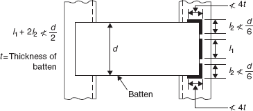
- The effective depth of intermediate battens should be equal to or more than 3/4 of the distance between the centroids of the components of the column. The effective depth of the end battens (tie plates) should be equal to or more than the distance between the centroids of the components of the column.
- The thickness of the batten (including tie plates) should not be less than 1/50 of the distance between the innermost connecting lines of bolts or welds.
- The spacing of battens centre to centre of the end fastenings should be such that the maximum slenderness ratio of the lesser component of the column over this spacing should not be more than 50 and 0.7 times the slenderness ratio of the member as a whole about the axis in the plane of battens.
- The batten or tie plates should overlap on the component members not less than 4 times the thickness of the plate (Figure 4.13).
- The length of weld connecting each end of the batten plate to the component of the column should not be less than half the depth of the batten (Figure 4.13). At least 1/3 of the weld should be placed at the corners. The welding should be returned along the other two edges of the plates transverse to the axis of the main member for a length not less than the minimum overlap.
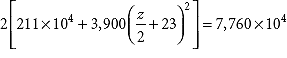
Design a built-up column of the effective length of 5 m to carry an axial load of 900 kN using lacing. Design the connections using fillet welds. The grade of the steel is E250.
The buckling of the built-up column belongs to class ‘c ‘ (from Table 4.3). Assume fcd as 150 N/mm2
The required sectional area ![]()
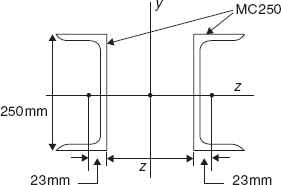
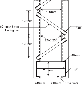
From Appendix A, 2 MC 300 may be tried.
The sectional area of these sections = 2 × 4,630 = 9,260 mm2
These are placed back to back as shown in Figure 4.14, the distance between them should be such that ry ≥ rz. Hence, rz becomes the minimum.
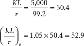
The effective slenderness ratio, ![]() = 1.05 × 42.4 = 44.5
= 1.05 × 42.4 = 44.5
From Table 4.4, for buckling class ‘c’, fcd = 194.4 N/mm2
The design load carrying capacity = 9,260 × 194.4 = 1,800 kN >> 1.5 × 900 kN
As the design load carrying capacity is much more than required, 2 MC250 may be tried.
From Appendix A, the sectional area of these sections = 2 × 3,900 = 7,800 mm2
Again, r = rz = 99.2 mm
From Table 4.4, for the buckling class ‘c’, fcd = 178.6 N/mm2
The design load carrying capacity = 7,800 × 178.6 = 1,393 kN > 1.5 × 900 kN
OK
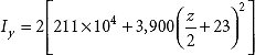
The minimum back to back distance between the sections z is calculated by equating Ix and Iy.
or
A spacing of 160 mm may be provided.
Design of lacing
From Appendix A, distance of centroid Cy = 23 mm
r = minimum of rz and ry of the component column (single channel) = 23.7 mm
The distance between the centroids of the channel sections = 160 + 23 + 23 = 206 mm
Using lacing bars at 500 angle,
the spacing of the lacing bars ![]() = 172.8mm ⇒ 175mm
= 172.8mm ⇒ 175mm
![]() of the component column =
of the component column = ![]() = 7.4 < 50 and < 0.7 × 50.4 = 35.3
= 7.4 < 50 and < 0.7 × 50.4 = 35.3
OK
The transverse shear force, V = 2.5 % of 1.5 × 900 kN = 33.75 kN
Using single lacing, the force in the lacing bar ![]()
The length of the lacing bar ![]() = 269 mm
= 269 mm
The effective length of the lacing bar = 0.7 × 269 =188 mm
Let the width of lacing bar = 50 mm
The thickness of the lacing bar ![]() = 6.7 mm
= 6.7 mm
50 mm × 8mm flat may be provided as the lacing bar
The min. moment of inertia of the lacing bar section ![]()
The minimum radius of the gyration of the lacing bar section ![]()
The slenderness ratio of the lacing bar = ![]() = 81.5 < 145
= 81.5 < 145
OK
From Table 4.4, for the buckling class ‘c’, fcd = 133.75 N/mm2
The load carrying capacity of the lacing bar in compression
The load carrying capacity of the lacing bar in tension
OK
Connection
For connecting 8 mm thick lacing bar with a 7.2 mm thick flange of channel section, the minimum size of the fillet weld = 3 mm.
The design shear strength of the weld,
The strength of the weld per mm = 0.7 × 3 × 189.4 = 398 N/mm
The length of the weld on each edge of the lacing bar ![]()
The minimum length of the lap = 4 times the maximum thickness of the connecting parts.
A 40 mm length of weld may be provided on each edge.
Tie plates
The depth of the tie plate = The distance between the centroids of the channel sections = 206 mm
The thickness of the tie plate ![]()
A 210 mm × 10 mm tie plate may be provided.
The length of the tie plate (with a minimum lap of 4 × 10 = 40 mm) = 160 + 2 × 40 = 240 mm
The length of the tie plate may be 240 mm with a 40 mm overlap on each side.
As calculated in the next example, 6 mm size fillet weld may be used to connect tie plates with the components of the column.
The details are shown in Figure 4.15.
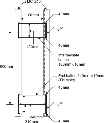
Re-design Example 4.7 using battening.
Again, 2 MC 250 may be tried.
Effective slenderness ratio ![]()
From Table 4.4, for the buckling class ‘c’, fcd = 175 N/mm2
The load carrying capacity of the column = 7,800 × 175 = 1,365 kN > 1.5 × 900 kN
OK
The minimum of rz and ry of the component column (single channel) = 23.7 mm
The slenderness ratio of the component column should be less than 50 or 0.7 × 55.4 = 38.8
∴ Maximum spacing of battens = 38.8 × 23.7 = 919 mm
A spacing of 900 mm may be provided.
The transverse shear force, V = 2.5% of 1.5 × 900 kN = 33.75 kN
The bending moment in the battens
The shear force in the batten
The minimum thickness of the batten
Using 10 mm thick battens, the depth of the batten d is given by
or
The minimum depth of the batten
180 mm × 10 mm battens may be provided.
The length of the batten (with a minimum lap of 4 × 10 = 40 mm) = 160 + 2 × 40 = 240 mm
The length of the batten may be 240 mm with a 40 mm overlap on each side.
Connection for intermediate battens
Let fillet weld is provided along the depth of batten and for 40 mm length of overlap as shown in Figure 4.16.
The distance of the centroid of the weld
![]()
The moment of inertia of the weld about x-axis,
![]()
The moment of inertia of the weld about y-axis,
![]()
= 32,820 mm3
The polar moment of inertia of the weld,
Ip = Ix + Iy = 11,34,000 + 32,820 = 11,66,820 mm3
The weld is subjected to a vertical shear force of 73,725.75 N and a twisting moment of 75,93,750 Nmm. The weld is designed as explained in Section 10.2.2.2.
The maximum vertical shear force in the weld per unit length
![]()
The maximum horizontal shear force in the weld per unit length
![]()
The design shear force in the weld per unit length
![]()
The design shear strength of the weld per unit length = 0.7s × 189.4
∴ 0.7s × 189.4 = 773
s = 5.8 mm
A 6 mm size of weld may be provided.
The Tie plates and their connection remain the same as in the laced column.
The details are shown in Figure 4.17.
Problems
For the following problems, consider the grade of the steel as E250
- Re-do Example 4.1 if the section of the column is WPB 200 × 200 × 83.52.
- Re-do Example 4.1 if the section of the column is 172 × 92 × 4.8 HF RHS. Assume that the ends of the column are rigidly connected.
- Design a single equal angle to carry a compression of 50 kN. The centre to centre distance between the end connections is 2 m. Assume that at least two bolts are used for the end connection.
- Design a compression member using two equal angles to carry a compression of 200 kN. The centre to centre distance between the end connections is 3 m. Assume that (a) the angles are placed on the same side of the gusset and (b) the angles are placed on both sides of the gusset.
- Design a laced built-up column of effective length 8 m to carry a load 1,000 kN using four equal angles. Use angles as lacing bars and their connection with main angles may be done using bolts.
- Design a welded laced column of effective length 6 m to carry a load of 600 kN using four tubular sections. Also, use tubular sections as lacing bars.
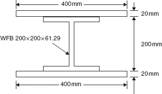
- Find the ultimate design load of the compression member whose cross section is shown in Figure 4.18. The effective length of the member is 4 m.
- Re-do Example 4.8 using 2 WPB sections and battening.
- Re-do Problem 4.6 using square hollow sections (SHS).