The electronic commerce software product line case study is a highly distributed World Wide Web–based product line that handles business-to-business (B2B) as well as business-to-consumer (B2C) systems. Because there are two main systems—B2B and B2C—the reverse evolutionary engineering strategy is applied first to each type of system, from which the product line commonality is determined, followed by the product line variability. The solution uses software agents as intermediaries between user interface clients and servers. In addition, object brokers provide a standardized interface to several heterogeneous legacy databases.
The problem is described in Section 14.1. Section 14.2 describes the use case model for the electronic commerce product line, starting by modeling the use cases for B2B systems and B2C systems before synthesizing the two use case models into a product line use case model. Section 14.3 goes on to discuss the electronic commerce software product line feature model, in which common, optional, and alternative features are determined from the use case model. Section 14.4 describes the product line static model, which includes the product line context model that depicts the boundary between a product line member and the external environment. This section also describes the use of software agents and broker technology in this product line, before going on to describe static modeling of the entity classes—initially modeling entity classes in B2C and B2B systems, and then integrating them into a product line static model. Section 14.5 describes dynamic modeling, in which communication diagrams are initially developed for each of the kernel use cases. This process continues during software product line evolution, as described in Section 14.6, in which communication diagrams are developed for each of the optional and alternative use cases. Section 14.7 discusses the feature/class dependency analysis, in which the classes that realize each feature are determined. Section 14.8 describes the design model for the electronic commerce software product line, which is designed as a layered architecture based on the Layers of Abstraction pattern combined with the Client/Agent/Server pattern. The design also develops a federated architecture linking the different business and customer organizations that operate in the e-commerce product line. Section 14.9 briefly describes software application engineering.
In electronic commerce B2B systems, there are customers and suppliers. Each customer has a contract with a supplier for purchases from that supplier, as well as one or more bank accounts through which payments to suppliers can be made. Each supplier provides a catalog of items, accepts customer orders, and maintains accounts with each customer for receiving payment.
A customer is able to browse through several World Wide Web–based catalogs provided by the suppliers and select items to purchase. The customer's order needs to be checked against the available contracts to determine if there is a valid customer contract with the supplier, which will be used for charging the purchase. Each contract has operation funds committed to it. It is necessary to determine that sufficient funds are available for the customer order. Assuming that the contract and funds are in place, a delivery order is created and sent to the catalog supplier. The supplier confirms the order and enters a planned shipping date. As time passes, the shipping order is monitored, and both supplier and customer are notified if there is a shipping delay. When the order is shipped, the customer is notified. The customer acknowledges when the shipment is received, and the delivery order is updated. After receipt of shipment, payment of the invoice is authorized. The invoice is first checked against the contract, available funds, and delivery order status, and then sent to Accounts Payable, which authorizes the payment of funds. Payment is made through electronic funds transfer from the customer bank to the supplier bank. The application uses several legacy databases, so object brokering and wrapper technologies are required.
Optionally, a supplier may create a purchase order (PO) requesting new inventory supplies from a wholesaler. The PO is sent directly to the wholesaler. When the PO is delivered to the supplier, the new supplies are entered into the supplier's inventory, and payment is made by electronic funds transfer from the supplier bank to the wholesaler bank.
In electronic commerce B2C systems, a customer requests to purchase one or more items from the supplier. The customer provides personal details, such as address and credit card information. This information is stored in a customer account. If the credit card is valid, then a delivery order is created and sent to the supplier. The supplier confirms the order and enters a planned shipping date. When the order is shipped, the customer is notified and the customer's credit card account is charged.
Because there are two main systems—B2B and B2C—in the electronic commerce product line, a reverse engineering approach is applied first to each type of system, from which the product line commonality is determined, followed by the product line variability.
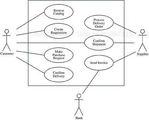
The use case model for B2B systems in the electronic commerce product line is depicted in Figure 14.1. There are three actors: Customer, Supplier, and Bank. The customer initiates four use cases: Browse Catalog, Create Requisition, Make Purchase Request, and Confirm Delivery. The supplier initiates three use cases: Process Delivery Order, Confirm Shipment, and Send Invoice. These are the main B2B use cases in the product line; other, less important use cases for querying the servers and monitoring progress have been omitted for brevity.
The B2B use cases are briefly described next. In the Browse Catalog use case, the customer browses the various World Wide Web catalogs, views various catalog items from a given supplier's catalog, and selects items from the catalog. In the Create Requisition use case, the customer makes a requisition request. The system has to find a customer contract with the catalog supplier for which there are sufficient operation funds. If a valid contract is found, the system authorizes the requisition and informs the customer. In Make Purchase Request, the customer asks the system to send a purchase request to the supplier.
Although an initial use case analysis might suggest that Create Requisition and Make Purchase Request should be combined into one use case (e.g., Place Requisition), the reason for splitting the two use cases is that Create Requisition applies only to B2B systems, while Make Purchase Request applies to all e-commerce systems.
In the Process Delivery Order use case, the supplier requests a delivery order, determines that the inventory is available to fulfill the order, and displays the order.
In the Confirm Shipment use case, the supplier prepares the shipment manually and then confirms the shipment.
In the Confirm Delivery use case, when the shipment arrives at the customer, the customer confirms the delivery. The operation funds are committed for payment.
In the Send Invoice use case, the supplier sends an invoice to the customer organization. After the customer confirms delivery, the invoice is approved by the customer organization's Accounts Payable department, and an electronic payment request is sent to the customer's bank.
The use case model for B2C systems in the electronic commerce product line is depicted in Figure 14.2. As in B2B systems, there are the three actors; this time, though, they are Customer, Supplier, and Authorization Center. The customer initiates three use cases: Browse Catalog, Check Customer Account, and Make Purchase Request. The supplier initiates three use cases: Process Delivery Order, Confirm Shipment, and Bill Customer.
Two of the B2C customer-initiated use cases—Browse Catalog and Make Purchase Request—are identical to B2B use cases; Check Customer Account, however, is different from any of the B2B use cases. In the Check Customer Account use case, the customer enters personal details. The system creates a customer account if one does not already exist. The customer's credit card is checked for validity and sufficient credit to pay for the requested catalog items. If the credit card check shows that the credit card is valid and has sufficient credit, then the customer purchase is approved.
Two of the B2C supplier-initiated use cases—Process Delivery Order and Confirm Shipment—are identical to B2B use cases; Bill Customer, on the other hand, is different. In the Bill Customer use case, the system retrieves the customer's credit card details from the customer account and sends a payment request to the credit card authorization center.
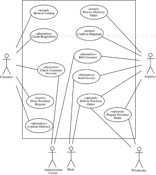
The supplier initiates two optional use cases that could be used in either B2B or B2C systems: Prepare Purchase Order and Deliver Purchase Order (see Figure 14.3). In the Prepare Purchase Order use case, the supplier checks inventory and requests creation of a purchase order for the inventory items that need to be replenished. In the Deliver Purchase Order use case, the system sends the purchase order to the wholesaler. When the delivery order arrives from the wholesaler, the supplier enters the information into the inventory database and approves electronic payment from the supplier bank to the wholesaler bank.
In the reverse engineering approach, the use cases from the various use case models (see Figures 14.1–14.3) are integrated to produce the product line use case model. Two of the customer-initiated use cases (Browse Catalog and Make Purchase Request) are common to all electronic commerce systems and so become kernel use cases of the product line. Similarly, two of the supplier-initiated use cases (Process Delivery Order and Confirm Shipment) are common to all electronic commerce systems, so they become kernel use cases. On the other hand, two of the customer use cases (Create Requisition and Confirm Delivery) are used only in B2B systems, and a third use case (Check Customer Account) is used only in B2C systems. On the supplier side, one use case (Send Invoice) is used only in B2B systems, and another use case (Bill Customer) is used only in B2C systems. Finally, the two purchase order use cases (Prepare Purchase Order and Deliver Purchase Order) are optional and could be used in either B2B or B2C systems.
The use cases that can be used in only B2B or only B2C systems, but not both, are categorized as alternative use cases. The optional purchase order use cases, which have no such restriction, are categorized as optional use cases. The use case model for the product line is shown in Figure 14.4.
In feature modeling, the requirements of the electronic commerce software product line are viewed from a reuse perspective. The kernel use cases are grouped into a common feature, called E-Commerce Kernel, and depicted as a use case package consisting of the Browse Catalog, Make Purchase Request, Process Delivery Order, and Confirm Shipment use cases. There are also two alternative features—Business Customer and Home Customer—corresponding to the two major uses of this product line for B2B and B2C systems, respectively. The use cases that are used only in B2B systems (Create Requisition, Confirm Delivery, and Send Invoice) are combined into the alternative feature called Business Customer. The use cases that are used only in B2C systems (Check Customer Account and Bill Customer) are combined into the alternative feature called Home Customer. There is an exactly-one-of feature constraint between the alternative Business Customer and Home Customer features, meaning that one and only one of these features must be selected for a given electronic commerce system that is a member of the product line:
«exactly-one-of feature group» Customer {alternative = Business
Customer, Home Customer}
The optional purchase order use cases (Prepare Purchase Order and Deliver Purchase Order) are combined into an optional Purchase Order feature because they are always reused together.
The grouping of use cases into features is depicted with the UML package notation in Figure 14.5a and in tabular form in Table 14.1. The feature group is depicted in Table 14.2. Figure 14.5b depicts a feature dependency diagram showing the dependencies between the features by using the metamodeling and stereotype notation introduced in Chapter 5. Figure 14.5b shows an additional feature, Bank, which is factored out as a separate optional feature because it is needed by both the Business Customer alternative feature and Purchase Order optional feature, as explained in more detail in Section 14.7. The Business Customer and Purchase Order features are both explicit features that mutually include the Bank feature because it is an implicit feature that cannot be selected by itself. The exactly-one-of feature group Customer contains two mutually exclusive features: the Business Customer and Home Customer alternative features.
Table 14.1. Feature/use case dependencies of the electronic commerce software product line
Feature Name | Feature Category | Use Case Name | Use Case Category |
|---|---|---|---|
E-Commerce Kernel | common | Browse Catalog | kernel |
Make Purchase Request | kernel | ||
Process Delivery Order | kernel | ||
Confirm Shipment | kernel | ||
Business Customer | alternative | Create Requisition | alternative |
Confirm Delivery | alternative | ||
Send Invoice | alternative | ||
Home Customer | alternative | Check Customer Account | alternative |
Bill Customer | alternative | ||
Purchase Order | optional | Prepare Purchase Order | optional |
Deliver Purchase Order | optional |
Table 14.2. Feature groups in the electronic commerce software product line
Feature Group Name | Feature Group Category | Features in Feature Group | Feature Category |
|---|---|---|---|
Customer | exactly-one-of | Business Customer | alternative |
Home Customer | alternative |
Many attributes need to be defined for any given member of the e-commerce product line. Several entity classes, as described in Section 14.4.4, have attributes that need to be populated when a member of the product family is derived from the product family architecture.
This section describes the static model, which consists of the product line context model and the entity class model. This section also discusses the use of brokering technology and agent technology in e-commerce product lines.
The product line context model depicts three external user classes, depicted as actors: the kernel Customer and Supplier classes, and the optional Wholesaler external user. Furthermore, the Customer actor is specialized into two variant actors: Business Customer and Home Customer. There are two optional external system classes: Authorization Center and Bank. In this product line the context diagram (see Figure 14.6) is very similar to the use case diagram because the external classes correspond to the actors on the use case diagram.
This section outlines an approach that uses software agents in the electronic commerce product line. In this example there are client agents and server agents, where each agent defines the business rules for a particular aspect of the electronic commerce problem domain. In this application the client agents are user agents that act on behalf of users and assist users in performing their jobs. To do this, the client agents interact with server agents. The server agents receive requests from client agents. To satisfy a client agent request, a server agent typically interacts with server objects and with other agents.
The use of software agents is illustrated conceptually in Figure 14.7 for B2B e-commerce systems. In the electronic commerce problem, there are two types of client agents: Customer Agent and Supplier Agent. There is one instance of the Customer Agent for each customer and one instance of the Supplier Agent for each supplier. There are several server agents, with many instances of each. The server agents are
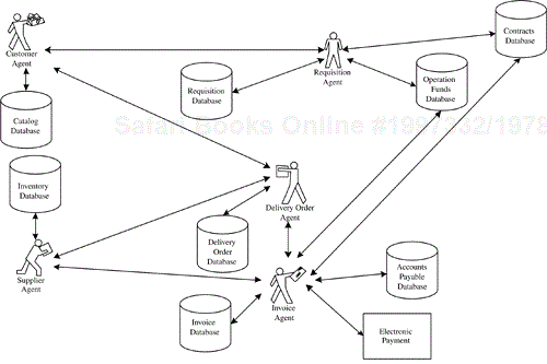
Note: This diagram does not use the UML notation.
Figure 14.7. Agent-based B2B electronic commerce system: conceptual view
Customer Agent (see Figure 14.7) is a client agent that acts on behalf of the human customer. Customer Agent assists the customer who wishes to order one or more items from a catalog. It takes the customer's request and interacts with the server agents to further the processing of the customer's selection and to track the status. The customer may select several items from a catalog. When a customer completes catalog selection, Customer Agent acts on behalf of the customer and initiates certain actions. In particular, when the customer makes a catalog selection, Customer Agent sends a requisition request to a Requisition Agent.
Requisition Agent is a server agent that queries various databases and communicates with various agents to ensure the processing of a customer-initiated requisition. It queries the requisition database, contracts database, and operation funds database, as well as communicating with Customer Agent. It sends a contract query to the contracts database to determine if a contract is in place. It sends a funds query to the operation funds database to determine if the funds are in place. If the response to both queries is positive, Requisition Agent authorizes the requisition and sends the requisition status to Customer Agent. Customer Agent sends a purchase request to Delivery Order Agent.
Supplier Agent is a client agent that is instantiated to work with the supplier. It retrieves a delivery order from Delivery Order Agent and helps the supplier fulfill the order. Supplier Agent updates the inventory database, and the order status is sent to Delivery Order Agent and Customer Agent. The customer eventually acknowledges receipt of the goods, and the delivery order is updated to reflect the receipt date.
Supplier Agent sends the invoice to Invoice Agent at the customer organization. When notified by Delivery Order Agent that the goods have been received, Invoice Agent queries the contracts database and the operation funds database (see Figure 14.7). If both responses are positive, Invoice Agent authorizes payment and sends the invoice to the accounts payable database, which updates the account. Invoice Agent then sends the electronic payment request to the customer's bank.
Billing Agent is used in B2C applications to handle the validation and billing of the customer's electronic purchase by interacting with various agents and servers, as well as with the credit card authorization center, as shown in Figure 14.8. Purchase Order Agent (also shown in Figure 14.8) is an optional server agent that addresses the preparation and delivery of a purchase order by interacting with various agents and servers, as well as with the external wholesaler and the bank.
Several legacy databases are used in the electronic commerce software product line. Each of these is a stand-alone database residing on a mainframe. These databases need to be integrated into the electronic commerce application by means of a broker technology (see Chapters 2 and 10 for more information on brokers).
The legacy databases in the customer organizations are the contracts database, the operation funds database, the requisition database, the invoice database, and the accounts payable database. The legacy databases in the supplier organizations are the catalog database, the inventory database, and the delivery order database.
To integrate these databases into the electronic commerce application, the server objects that access them need to be database wrapper objects that encapsulate the details of how to read and update the individual databases. Thus, Requisition Server, Contracts Server, Operation Funds Server, Accounts Payable Server, Invoice Server, Catalog Server, Delivery Order Server, and Inventory Server are all database wrapper objects.
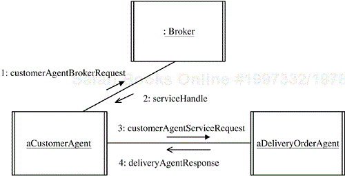
In addition, to maintain low coupling between clients, agents, and servers, a broker naming service is used to maintain the location of the specific services. Servers and agents register their services and locations with the object broker. When a service is required, a message is sent to the broker to determine the location of the service. An example is given in Figure 14.9 in which a client agent, Customer Agent, determines from the broker the location of a server agent, Delivery Order Agent. Customer Agent then communicates directly with Delivery Order Agent.
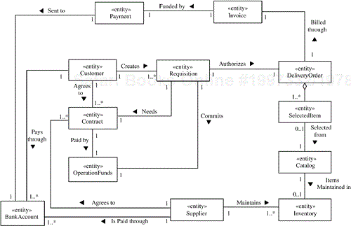
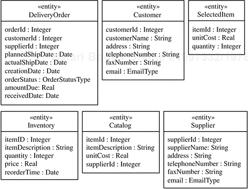
A static model of the problem domain is developed and depicted on a class diagram (see Figure 14.10). Because this is a data-intensive application, the emphasis is on the entity classes, many of which represent the data stored in the legacy databases. The database wrapper objects will map between the conceptual objects and the actual databases. Because each customer and supplier organization is liable to have its own specific legacy database, many individual solutions to the wrapper problem are likely to exist. But if broker and wrapper technology is used, it is possible to have a systematic way of integrating the disparate legacy databases into a general solution.
The electronic commerce software product line has two main groups of applications: B2C applications and B2B applications. The static entity class model for B2C applications is depicted in Figure 14.10, which shows the entity classes for all the important problem domain entities and the relationships among these classes. The classes include home customer classes (Customer and Customer Account), supplier classes (such as Supplier, Inventory, and Catalog), and classes that deal with the customer's order (such as Delivery Order, which is an aggregation of Selected Item).
The static entity class model for B2B applications is shown in Figure 14.11. These classes include business customer classes (such as Requisition, Contract, and Operation Funds), supplier classes (such as Catalog and Inventory), and classes that deal with the customer's order and payment (such as Delivery Order, Payment, and Invoice).
The integrated static entity class model for the product line is shown in Figure 14.12. In the product line static model, classes have a second stereotype to depict the reuse category of each class: either «kernel» or «optional». Classes such as Customer and Catalog, which exist in the static models of both B2C and B2B applications, become kernel classes in the product line static model. Classes that appear in only one of the static models, such as Contract (which appears only in the B2B static model) and Customer Account (which appears only in the B2C static model), become optional classes in the product line static model. Entity classes that might exist in either a B2B or a B2C application, such as Purchase Order, also become optional classes in the product line static model.
The attributes for the kernel and optional classes are shown in Figures 14.13 and 14.14, respectively. Many of the class attributes need to be defined at configuration or initialization time before a member of the product family can become operational. Included are attributes for the kernel classes, as well as for the optional and variant classes selected for the product line member. For a B2B system, these include attributes for the Customer, Supplier, Contract, Operation Funds, and Bank Account classes.
The entity classes determined in the previous section will all be incorporated into the server classes, which will provide the necessary legacy database wrapping as described in Section 14.4.3. User interface classes are needed to interact with the external users—in particular, Customer Interface and Supplier Interface. Furthermore, the software agents described in Section 14.4.2 are also needed.
For each use case, a communication diagram is developed depicting the objects that participate in the use case and the sequence of messages passed between them. With the kernel first approach, the communication diagrams for the four kernel use cases are developed first.
In the communication diagram for the Browse Catalog use case (Figure 14.15), Customer Interface interacts with Customer Agent, which in turn communicates with Catalog Server. The message descriptions are as follows:
A1: The customer makes a catalog request via
Customer Interface.A2:
Customer Agentis instantiated to assist the customer. On the basis of the customer's request,Customer Agentselects one or more catalogs for the customer to browse.A3:
Customer Agentrequests information fromCatalog Server.A4:
Catalog Serversends catalog information toCustomer Agent.A5:
Customer Agentforwards the information toCustomer Interface.A6:
Customer Interfacedisplays the catalog to the customer.A7: The customer makes a catalog selection through
Customer Interface.A8:
Customer Interfacepasses the request on toCustomer Agent.A9:
Customer Agentrequests the catalog selection fromCatalog Server.A10:
Catalog Serverconfirms the availability of the catalog items toCustomer Agent.A11:
Customer Agentforwards the information toCustomer Interface.A12:
Customer Interfacedisplays the catalog confirmation to the customer.
In the communication diagram for the Make Purchase Request use case (Figure 14.16), Customer Agent sends a purchase request to Delivery Order Agent and receives a confirmation. The message descriptions are as follows:
P1: The customer makes a purchase request.
P2:
Customer Interfacesends the purchase request toCustomer Agent.P3:
Customer AgentinstantiatesDelivery Order Agentand sends the purchase request to it.P4:
Delivery Order Agentcreates a new delivery order and stores it withDelivery Order Server.P5:
Delivery Order Agentsends a purchase request confirmation with the order ID toCustomer Agent.P6:
Customer Agentsends the purchase request confirmation toCustomer Interface.P7:
Customer Interfacedisplays the purchase request status to the customer.
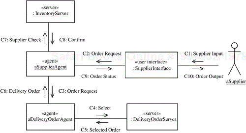
In the communication diagram for the next use case, Process Delivery Order (Figure 14.17), Supplier Agent queries Delivery Order Agent for a new delivery order, and Delivery Order Agent selects a delivery order. Supplier Agent checks the inventory and displays the order and inventory information to the supplier via the user interface. The message descriptions are as follows:
C1: The supplier requests a new delivery order.
C2:
Supplier Interfaceforwards the request toSupplier Agent.C3:
Supplier Agentsends the order request toDelivery Order Agent.C4, C5:
Delivery Order Agentselects a delivery order by queryingDelivery Order Server.C6:
Delivery Order Agentsends the delivery order toSupplier Agent.C7, C8:
Supplier Agentchecks that the items are available in inventory.C9:
Supplier Agentsends the order status toSupplier Interface.C10:
Supplier Interfacedisplays the delivery order and inventory information to the supplier.
In the communication diagram for the Confirm Shipment use case (Figure 14.18), the supplier prepares the shipment manually. The supplier then confirms the shipment by entering the shipping information, including the shipping date. Supplier Agent updates the inventory, and the order status is sent to Delivery Order Agent and to Customer Agent, which displays the order status to the customer. The message descriptions are as follows:
S1: The supplier inputs the shipping information.
S2:
Supplier Interfacesends the confirm shipment request toSupplier Agent.S3:
Supplier Agentupdates the inventory stored atInventory Server.S4:
Supplier Agentsends the order status toDelivery Order Agent.S5:
Delivery Order AgentupdatesDelivery Order Server.S6:
Delivery Order Agentsends the order status toCustomer Agent.S7:
Customer Agentforwards the order status toCustomer Interface.S8:
Customer Interfacedisplays the order status to the customer.
With the product line evolution approach, the communication diagrams are next developed for the optional and alternative use cases.
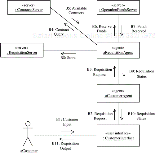
In the communication diagram for the Create Requisition use case (Figure 14.19), Requisition Agent sends a contract query to Contracts Server to determine if a contract is in place. It also sends a funds query to Operation Funds Server to determine if the funds are in place. If the response to both queries is positive, Requisition Agent authorizes the requisition and sends the requisition status to Customer Agent. The message descriptions are as follows:
B1: The customer selects items from the catalog and requests the creation of a requisition.
B2:
Customer Interfaceforwards the request toCustomer Agent.B3:
Customer AgentinstantiatesRequisition Agent, passing to it the customer's requisition request.B4:
Requisition Agentsends a contract query toContracts Server.B5:
Contracts Serverreturns the contracts available between the customer and the supplier.B6:
Requisition Agentsends aReserve Fundsrequest toOperation Funds Serverto hold the funds from a given contract for this requisition.B7:
Operation Funds Serverconfirms that the funds have been reserved.B8:
Requisition Agentapproves the requisition and sends it to be stored atRequisition Server.B9:
Requisition Agentsends the requisition status toCustomer Agent.B10:
Customer Agentsends the requisition status toCustomer Interface.B11:
Customer Interfacesends the requisition status to the customer.
In the communication diagram for the Confirm Delivery use case (Figure 14.20), when the shipment arrives at the customer, the customer acknowledges receipt of the goods, and the delivery order is updated to reflect the receipt date. Requisition Agent is also notified. The message descriptions are as follows:
R1: The customer acknowledges receipt of the shipment.
R2:
Customer Interfacesends the customer confirmation toCustomer Agent.R3:
Customer Agentsends aShipment Receivedmessage toDelivery Order Agent.R4:
Delivery Order Agentupdates the status atDelivery Order Server.R5:
Customer Agentsends aShipment Receivedmessage toRequisition Agent.R6:
Requisition Agentupdates the status of the requisition stored atRequisition Server.R7, R8:
Requisition Agentcommits the funds for this requisition withOperation Funds Server.
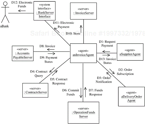
Because the supplier confirmed in the Confirm Shipment use case (see Figure 14.18) that the goods were sent to the customer, Supplier Agent sends the invoice automatically, as shown in the communication diagram for the Send Invoice use case (Figure 14.21). The arrival of the invoice at the customer organization causes the instantiation of Invoice Agent to follow through on the invoice. Invoice Agent subscribes to Delivery Order Agent to be notified when the goods have been received. When notified of the receipt of the goods, Invoice Agent queries Contracts Server and Operation Funds Server. If both responses are positive, Invoice Agent authorizes payment and sends the invoice to Accounts Payable Server, which updates the account. Invoice Agent then sends the electronic payment to the customer's bank server and the invoice status to the supplier. The message descriptions are as follows:
D1:
Supplier Agentsends the invoice information toInvoice Agent.D2:
Invoice Agentsubscribes toDelivery Order Agent.D3:
Delivery Order AgentnotifiesInvoice Agentthat the goods have been received.D4:
Invoice Agentsends a contract query toContracts Server.D5:
Contracts Serverconfirms the contract.D6:
Invoice Agentsends a funds commitment request toOperation Funds Server.D7:
Operation Funds Serverconfirms that the funds are available and committed.D8:
Invoice Agentsends the invoice toAccounts Payable Server.D9:
Accounts Payable Serversends the payment status toInvoice Agent.D10:
Invoice Agentstores the invoice atInvoice Server.D11:
Invoice Agentsends the electronic payment to the customer's bank viaBank Server Interface.D12:
Bank Server Interfacesends the electronic funds to the customer's bank for payment to the supplier.D13:
Invoice Agentsends the invoice status toSupplier Agent.
In the communication diagram for the Prepare Purchase Order use case (Figure 14.22), the supplier requests a new purchase order to replenish low inventory. This interaction involves a new agent, Purchase Order Agent, as well as Purchase Order Server and an interface to the wholesaler, who has to fill the purchase order. The message descriptions are as follows:
K1: The supplier provides purchase order details.
K2:
Supplier Interfacesends the purchase order information toSupplier Agent.K3:
Supplier Agentsends the PO request toPurchase Order Agent.K4:
Purchase Order Agentchecks the inventory viaInventory Server.K5:
Inventory Serverresponds with current inventory levels for the items of interest.K6:
Purchase Order Agentstores the purchase order withPurchase Order Server.K7:
Purchase Order Agentplaces the purchase order withWholesaler Interface.K8:
Wholesaler Interfacedelivers the purchase order to the wholesaler.K9, K10, K11:
Purchase Order Agentconfirms toSupplier Agentthe sending of the purchase order, andSupplier AgentinformsSupplier Interface, which in turn informs the supplier.
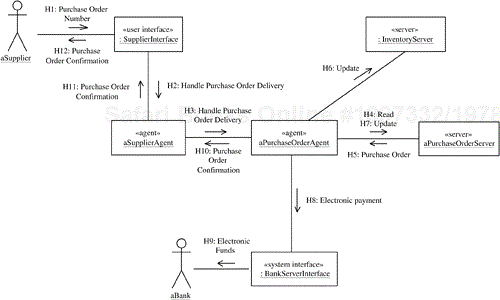
In the communication diagram for the Deliver Purchase Order use case (Figure 14.23), the supplier receives a new purchase order to replenish low inventory. Purchase Order Agent interacts with Purchase Order Server and Inventory Server, as well as with Bank Server Interface. The message descriptions are as follows:
H1: The supplier receives a new purchase order and inputs the purchase order to
Supplier Interface.H2:
Supplier Interfacesends aHandle Purchase Order Deliveryrequest toSupplier Agent.H3:
Supplier Agentforwards this request with the PO number toPurchase Order Agent.H4, H5:
Purchase Order Agentrequests the purchase order fromPurchase Order Server.H6:
Purchase Order Agentsends an update message toInventory Serverto update the inventory with the new items received.H7:
Purchase Order Agentsends an update message toPurchase Order Serverto record that the PO has been serviced.H8, H9:
Purchase Order Agentsends an electronic payment for the wholesaler to the bank viaBank Server Interface.H10, H11, H12:
Purchase Order Agentconfirms delivery of the purchase order toSupplier Agent, which informsSupplier Interface, which in turn informs the supplier.
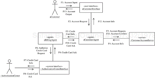
The communication diagram for the Check Customer Account use case (Figure 14.24) addresses the B2C case in which a customer provides the account information, which is checked by Customer Agent in conjunction with Billing Agent. The message descriptions are as follows:
F1: The customer provides account input to
Customer Interface.F2:
Customer Interfacesends the account request toCustomer Agent.F3, F4:
Customer Agentsends the account request toCustomer Account Serverand receives the account information, including the customer's credit card details.F5:
Customer Agentsends the customer's credit card information toBilling Agent.F6, F7:
Billing Agentsends a credit card request toAuthorization Center Interface, which forwards the request to the authorization center.F8, F9:
Authorization Centersends a credit card acknowledgment toBilling AgentviaAuthorization Center Interface.F10, F11:
Billing Agentforwards the credit card acknowledgment toCustomer Agent, which sends an account confirmation toCustomer Account Server.F12, F13:
Customer Agentsends the account information toCustomer Interface, which outputs it to the customer.
An alternative to this use case is that the customer does not have an account, in which case an account will be created.
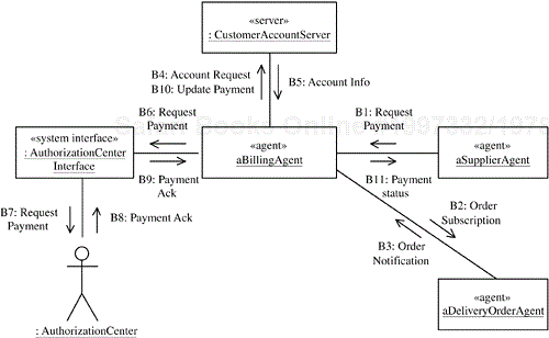
The communication diagram for the Bill Customer use case (Figure 14.25) addresses the B2C case in which a customer is billed for the purchase. This use case involves Supplier Agent and Billing Agent, as well as electronic billing. Because the supplier confirmed in the Confirm Shipment use case (see Figure 14.18) that the goods were sent to the customer, Supplier Agent sends the payment request automatically, as shown in Figure 14.25. The message descriptions are as follows:
B1:
Supplier Agentsends the payment request for billing the customer toBilling Agent.B2:
Billing Agentsubscribes toDelivery Order Agentto receive notification of order completion.B3:
Delivery Order AgentnotifiesBilling Agentof order completion.B4, B5:
Billing Agentrequests the customer's credit card information fromCustomer Account Serverand receives the information.B6:
Billing Agentforwards the request toAuthorization Center Interface.B7:
Authorization Center Interfacesends the billing information to the external authorization center.B8: The authorization center acknowledges that it has billed the customer and returns a billing reference number.
B9:
Authorization Center Interfacesends the billing reference number toBilling Agent.B10:
Billing Agentsends the billing reference number toCustomer Account Server.B11:
Billing Agentsends the payment status toSupplier Agent.
The feature/class dependencies of the electronic commerce software product line are shown in Table 14.3. There are kernel components, Business Customer components, Home Customer components, and optional Purchase Order and Bank components.
Table 14.3. Feature/class dependencies of the electronic commerce software product line
Feature Name | Feature Category | Class Name | Class Category |
|---|---|---|---|
E-Commerce Kernel | common | Customer Interface | kernel-abstract-vp |
Customer Agent | kernel-abstract-vp | ||
Supplier Interface | kernel-vp | ||
Supplier Agent | kernel-vp | ||
Catalog Server | kernel | ||
Delivery Order Agent | kernel | ||
Delivery Order Server | kernel | ||
Inventory Server | kernel | ||
Business Customer | alternative | B2B Customer Interface | variant |
B2B Customer Agent | variant | ||
Requisition Agent | optional | ||
Requisition Server | optional | ||
Contracts Server | optional | ||
Operation Funds Server | optional | ||
Invoice Agent | optional | ||
Invoice Server | optional | ||
Accounts Payable Server | optional | ||
Home Customer | alternative | B2C Customer Interface | variant |
B2C Customer Agent | variant | ||
Billing Agent | optional | ||
Customer Account Server | optional | ||
Authorization Center Interface | optional | ||
Purchase Order | optional | Purchase Order Agent | optional |
Purchase Order Server | optional | ||
Wholesaler Interface | optional | ||
Purchase Order Supplier Interface | variant | ||
Purchase Order Supplier Agent | variant | ||
Bank | optional | Bank Server Interface | optional |
To identify the kernel components, it is necessary to analyze the communication diagrams that support the kernel use cases. Table 14.1 shows that the kernel use cases that support the common E-Commerce Kernel feature are Browse Catalog, Make Purchase Request, Process Delivery Order, and Confirm Shipment. Analyzing the communication diagram for Browse Catalog (Figure 14.15) indicates that the kernel objects are Customer Interface, Customer Agent, and Catalog Server. For Make Purchase Request, the communication diagram (Figure 14.16) shows that Delivery Order Agent and Delivery Order Server are also kernel objects. The communication diagram for Process Delivery Order (Figure 14.17) shows that Supplier Interface, Supplier Agent, and Inventory Server are additional kernel objects. The final communication diagram for a kernel use case is Confirm Shipment (Figure 14.18). However, the objects on this diagram have already been accounted for in the previous diagrams. Each of the identified kernel objects is an instance of a kernel class. The feature/class dependencies for the kernel e-commerce product line are shown in Table 14.3.
To determine the components in the Business Customer feature, it is necessary to analyze the communication diagrams for the alternative use cases that support this alternative feature—namely, Create Requisition, Confirm Delivery, and Send Invoice, as shown in Table 14.1. Analysis of the Create Requisition communication diagram (Figure 14.19) identifies several objects: Customer Interface, Customer Agent, Requisition Agent, Requisition Server, Contracts Server, and Operation Funds Server. Because the first two objects behave differently in B2B systems, it is necessary to classify them further as B2B Customer Interface and B2B Customer Agent. From the Confirm Delivery communication diagram (Figure 14.20), no further objects are added because the only new objects compared to Create Requisition—namely, Delivery Order Agent and Delivery Order Server—have already been categorized as kernel objects. However, the final communication diagram for the alternative Send Invoice use case (Figure 14.21), adds several more objects: Invoice Agent, Invoice Server, and Accounts Payable Server. Supplier Agent has already been categorized as a kernel object.
At first glance, it would seem that Bank Server Interface should also be a class that supports the Business Customer feature. However, because this class is also needed in the Purchase Order feature, it is instead split off and allocated to its own feature, the Bank optional feature. Bank is an additional feature that is determined at design time and results when a class that is needed by two variable features is factored out. The feature/class dependencies for the alternative Business Customer feature are shown in Table 14.3.
To determine the components in the Home Customer feature, it is necessary to analyze the communication diagrams for the alternative use cases that support this alternative feature—namely, Check Customer Account and Bill Customer—as shown in Table 14.1. Analysis of the Check Customer Account communication diagram (Figure 14.24) determines that several objects support this feature: Customer Interface, Customer Agent, Billing Agent, Customer Account Server, and Authorization Center Interface. Because the first two objects behave differently in B2C systems, it is necessary to classify them further as B2C Customer Interface and B2C Customer Agent. From the Bill Customer communication diagram (Figure 14.25), no further objects are necessary. The feature/class dependencies for the alternative Home Customer feature are shown in Table 14.3.
To determine the components in the Purchase Order feature, it is necessary to analyze the communication diagrams for the optional use cases that support this optional feature—namely, Prepare Purchase Order and Deliver Purchase Order—as shown in Table 14.1. Analysis of the Prepare Purchase Order communication diagram (Figure 14.22) determines that five objects support this feature: Supplier Interface, Supplier Agent, Purchase Order Agent, Purchase Order Server, and Wholesaler Interface. Because the first two objects behave differently when handling purchase orders, it is necessary to classify them further as Purchase Order Supplier Interface and Purchase Order Supplier Agent. The only additional object, which comes from the Deliver Purchase Order communication diagram (Figure 14.23), is Bank Server Interface, which has already been allocated to the Bank feature. The feature/class dependencies for the optional Purchase Order feature are shown in Table 14.3.
The electronic commerce software product line is designed as a layered architecture based on the Layers of Abstraction architecture pattern. In addition, this product line uses the Client/Agent/Server pattern. In particular, it uses a variation of the pattern that has two types of agents: a client agent and a server agent. Both the Layers of Abstraction and the Client/Agent/Server patterns are described in Chapter 10.
The kernel of the electronic commerce software product line is designed to consist of those components that are needed by all members of the product line. Because of the integration of the Client/Agent/Server pattern with the Layers of Abstraction pattern, the kernel of the product line actually encompasses four layers of the architecture. The B2C and B2B systems, which are two major members of the product line, are designed with optional and alternative components that complement and use the kernel components. Because this product line needs to be highly flexible and distributed, the decision is made to design a distributed component-based software architecture.
Because the electronic commerce software product line is an interorganizational product line involving multiple organizations, it is actually a federated system as well as being a distributed system. In particular, in the B2B versions of the product line, some components are business customer components while other components are supplier components. Because of the characteristics of this product line, it is useful to design higher-level abstractions than individual components, which are high-level aggregate subsystems that encompass multiple components. Thus, the Client/Agent/Server pattern is applied on a subsystem-by-subsystem basis.
There are six aggregate subsystems, as follows:
Supplier Organization Subsystem(one instance per supplier organization)Business Customer Organization Subsystem(one instance per customer organization)Home Customer Subsystem(one instance per home customer)Purchase Order Subsystem(one instance per wholesaler)Bank Subsystem(one instance per bank)Authorization Subsystem(one instance per credit card company)
Each subsystem can be depicted as a package that contains the components in that subsystem, depicted as classes. Each component is depicted with two stereotypes: the component stereotype (what kind of component it is, as specified by the component structuring criteria) and the product line stereotype (the reuse category, such as kernel, optional, or variant). The components in each subsystem are determined by analysis of the communication diagrams for those use cases that are required for B2C and B2B systems, respectively.
One additional consideration is that some of the objects behave differently in B2B systems than in B2C systems. In particular, this situation applies to the Customer Interface and Customer Agent classes. It is therefore necessary to design B2B and B2C variants of these classes. The kernel class is designed as a kernel abstract class, which captures the generalized properties of the class and provides an interface that is inherited by the subclasses. Each subclass then provides additional behavior specific to its needs. The generalization/specialization hierarchy for the Customer Interface and Customer Agent classes is shown in Figure 14.26.
The components are structured into the layered architecture such that each component is in a layer where it needs the services provided by components in the layers below but not the layers above. This layered architecture is based on the Flexible Layers of Abstraction pattern, which is a less restrictive variant of the Layers of Abstraction pattern in which a layer can use the services of any of the layers below it, not just the layer immediately below it. This architecture facilitates adaptation of the electronic commerce software product line architecture to derive individual application members of the product line. User interface components at the user interface layer communicate only with client agent components. Client agent components communicate with server agent components and server components. Server agent components communicate with server components. Applying the component structuring criteria, the following components, organized by subsystem and layer are determined:
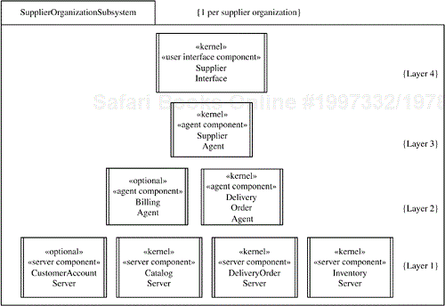
Supplier Organization Subsystem (see Figure 14.27) consists of the kernel supplier components, together with the optional Billing Agent and Customer Account Server components, which are used only in B2C systems:
Layer 1: Server components. There are three kernel server components (
Catalog Server,Delivery Order Server, andInventory Server) and one optional server component (Customer Account Server).Layer 2: Server agent components. There are two server agents: the kernel
Delivery Order Agentand the optionalBilling Agent.Layer 3: Client agent components. There is one kernel client agent:
Supplier Agent.Layer 4: User interface component. There is one kernel user interface component:
Supplier Interface.
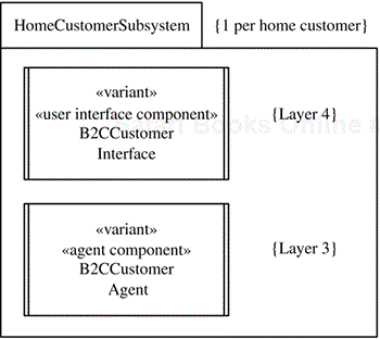
Home Customer Subsystem (see Figure 14.28) consists of the variant B2C Customer Interface and B2C Customer Agent components:
Layer 1: Server components. There are no server components.
Layer 2: Server agent components. There are no server agent components.
Layer 3: Client agent components. There is one variant client agent:
B2C Customer Agent.Layer 4: User interface component. There is one variant user interface component:
B2C Customer Interface.
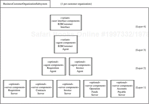
Business Customer Organization Subsystem (see Figure 14.29) consists of the variant B2B Customer Interface and B2B Customer Agent components, as well as several optional components that are used only in B2B systems:
Layer 1: Server components. There are several optional server components:
Requisition Server,Contracts Server,Invoice Server,Operation Funds Server, andAccounts Payable Server.Layer 2: Server agent components. There are two optional server agents:
Requisition AgentandInvoice Agent.Layer 3: Client agent components. There is one variant client agent:
B2B Customer Agent.Layer 4: User interface component. There is one variant user interface component:
B2B Customer Interface.
Purchase Order Subsystem (see Figure 14.30) consists of optional components that exist at two layers and can be used with either B2B or B2C systems:
Layer 1: Server components. There is one optional server component (
Purchase Order Server) and one optional system interface component (Wholesaler Interface).Layer 2: Server agent components. There is one optional server agent:
Purchase Order Agent.Layer 3: Client agent components. There are no client agents.
Layer 4: User interface component. There is no user interface component.
Bank Subsystem and Authorization Subsystem (see Figure 14.30) have one server component each: the Bank Server Interface and Authorization Center Interface components, respectively.
To handle the variety of communication between the components in the product line architecture, several communication patterns are applied:
Synchronous Message Communication with Reply. This is the typical client/server pattern of communication and is used when the client needs information from the server and cannot proceed before receiving the response. This pattern is used between user interface clients and client agents. It is also used between server agents and various servers, which are primarily database wrappers.
Broker Handle. Broker patterns are used during system initialization. Servers register their services and locations with the broker. The Broker Handle pattern allows clients to query the broker to determine the servers to which they should be connected.
Subscription/Notification (Multicast).
Invoice Agentin B2B systems andBilling Agentin B2C systems both subscribe toDelivery Order Agentto be informed when a delivery order has been completed.Customer Agent, in both B2C and B2B systems, subscribes toDelivery Order Agentto be informed of the status of the delivery order as it is processed.Asynchronous Message Communication. This pattern is used for
Customer Agentto asynchronously sendCustomer Interfacethe status of the delivery order after receiving it fromDelivery Order Agent.
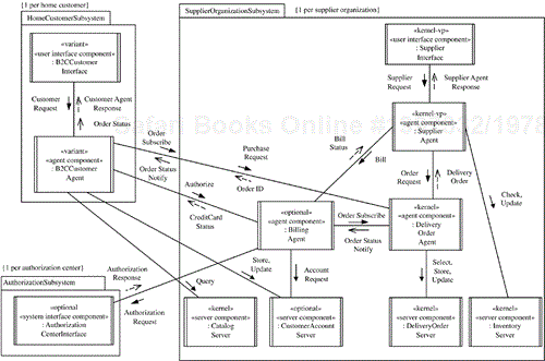
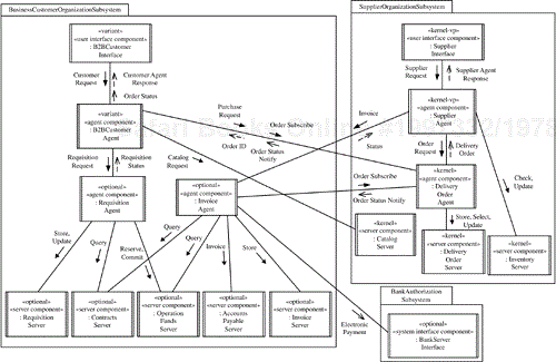
The concurrent communication diagrams for the B2C and B2B systems, shown in Figures 14.31 and 14.32, respectively, depict the concurrent components in the major applications that can be derived from the electronic commerce software product line architecture. They represent integrated generic communication diagrams determined from the individual communication diagrams supporting the use cases for B2C and B2B systems, respectively.
To keep the design simple, the Synchronous Message Communication with Reply pattern has been widely used in this case study. As described in Chapter 10, however, this approach has the disadvantage of suspending the client while it awaits a response from the server. An alternative design to avoid suspending the client is to use the Asynchronous Message Communication with Callback pattern. Examples of asynchronous communication are widely used in the microwave oven and factory automation product line case studies (Chapters 13 and 15, respectively).
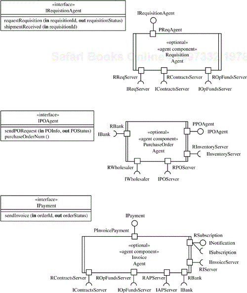
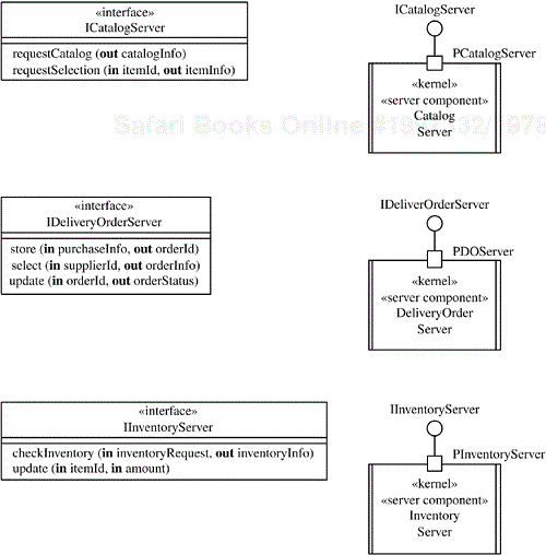
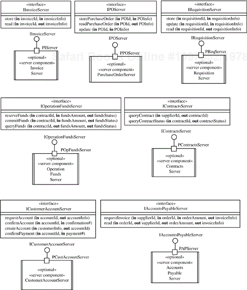
The design of the components and component interfaces within the overall product line architecture is depicted in Figures 14.33 through 14.36. Each component has one or more ports, with provided interfaces, required interfaces, or both. In the four-layer architecture, each client user interface component has one required port, which supports a required interface. Each server has one provided port, which supports a provided interface. The agents have ports with both required and provided interfaces because they act as intermediaries between the clients and agents. Whereas clients and servers each have one port through which they can communicate, agents communicate through multiple ports because each one needs to communicate with several components.
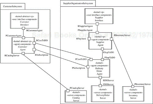
The kernel components and ports are depicted in the kernel software architecture diagram in Figure 14.33. In Customer Subsystem, which consists of two kernel abstract classes, Customer Interface is a client and thus has only a required port. Customer Agent has both required and provided ports. Both of these components capture the commonality among all customers, home and business. In Supplier Organization Subsystem, the Supplier Interface and Supplier Agent components provide the same functionality in both B2B and B2C systems, and the three servers also provide common functionality. Both Supplier Agent and Delivery Order Agent also provide functionality accessed via ports, which are used by different B2B and B2C components.
Consider the software architecture for B2C systems. In Home Customer Subsystem, both B2C Customer Interface and B2C Customer Agent are variant components, which are specialized from the kernel components to provide additional B2C functionality, as shown in Figure 14.34. B2C Customer Agent also adds two required ports, which support required interfaces to two optional components in Supplier Organization Subsystem that operate only in B2C applications: Billing Agent and Customer Account Server. To bill for customer purchases from the supplier, Supplier Agent communicates through a connector that joins its RPayment required port to Billing Agent's PBillPayment provided port. For the subscription/notification service, a bidirectional connector joins the RSubscription required port of the subscriber (Billing Agent) to the PSubscription provided port of Delivery Order Agent. The connector is bidirectional because Billing Agent sends a subscription message to Delivery Order Agent, which later responds with the notification. Customer payment is made by credit card, necessitating the optional Authorization Center Interface component.
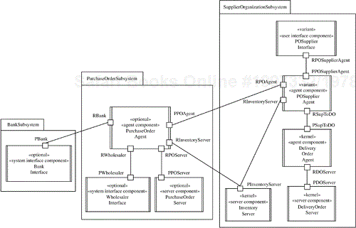
In the software architecture for B2B systems (see Figure 14.35), Business Customer Organization Subsystem is much more complex than Home Customer Subsystem. In addition to variant B2B Customer Interface and B2B Customer Agent components, there are several optional agent and server components added to provide the B2B functionality. B2B customer billing is handled differently, with the optional Invoice Agent handling customer payment. For this purpose, a connector now joins Supplier Agent's RPayment required port to Invoice Agent's PInvoicePayment provided port. In B2B systems, it is Invoice Agent that subscribes to Delivery Order Agent's subscription/notification service. Payment is made by electronic funds transfer via a request to the optional Bank Interface component.
If optional purchase order (PO) functionality is needed in either B2B or B2C systems, variant PO Supplier Interface and PO Supplier Agent components provide the additional PO functionality to initially make the order and then later install the delivered items. An optional Purchase Order Subsystem is also added, consisting of three optional components, as shown in Figure 14.36. Electronic payment is made by Purchase Order Agent via the optional Bank Interface component, which is also used in B2B applications.
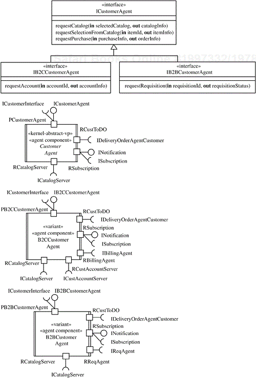
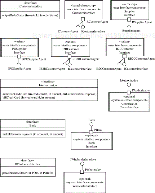
The ports and interfaces for each component are described next. The component ports and interfaces for Customer Agent are depicted in Figure 14.37. A generalized interface is shown for Customer Agent, which is specialized to the interfaces for B2C Customer Agent and B2B Customer Agent, respectively. There is a corresponding Customer Agent component to realize each interface, with the ports and interfaces depicted on the customer agent component diagram. Each Customer Agent component has a bidirectional port to communicate with Customer Interface, thereby allowing for asynchronous responses from the agent. All other ports have required interfaces because Customer Agent is a client agent that initiates communication with server agents as well as with server components.
Billing Agent, which is an optional server agent, has five ports because it communicates with five components, as shown in Figure 14.38. It receives client requests from Customer Agent through the PBillingAgent port, which supports a provided interface called IBillingAgent. In its role as a client, Billing Agent has two required interfaces for communication with Customer Account Server and Authorization Center Interface. Its interaction with Supplier Agent and Delivery Order Agent has already been described.
Delivery Order Agent is a kernel server agent that operates in both B2B and B2C applications. However, it is designed to be versatile so that it can operate with different components, as shown in Figure 14.39. Delivery Order Agent has one provided interface to receive requests from Supplier Agent and another to receive requests from Customer Agent, either the B2B or B2C variant. It provides a subscription service via a bidirectional port to allow asynchronous responses to its subscribers. Finally, Delivery Order Agent has a required interface to allow it to be a client to Delivery Order Server.
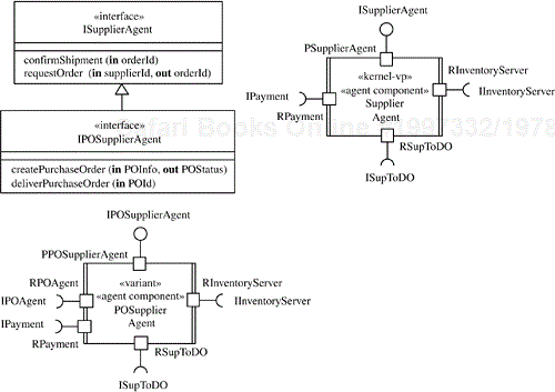
Supplier Agent (see Figure 14.40) provides the same functionality for B2B systems and B2C systems. It receives supplier requests via the PSupplierAgent port, which supports a provided interface called ISupplierAgent. However, PO Supplier Agent can additionally provide optional functionality for purchase orders. This functionality is handled through a specialized provided interface for PO requests called IPOSupplierAgent and a required interface (IPOAgent) to communicate with Purchase Order Agent. The component and port interfaces for the other optional agents (Requisition Agent, Purchase Order Agent, and Invoice Agent) are designed in a similar way, as depicted in Figure 14.41.
The component ports and interfaces for the server components—both kernel (Figure 14.42) and optional (Figure 14.43)—are all handled in the same way; each component has one port and provided interface through which the services are accessed. The clients of the server invoke the appropriate services synchronously.
Figure 14.44 shows the ports and interfaces for the user interface and system interface components. The required ports and required interfaces for the variant Customer Interface user interface components (see Figure 14.44), are specialized from a generalized ICustomerAgent interface into B2C and B2B versions (see Figure 14.37). The optional system interface components (Bank Interface, Authorization Center Interface, and Wholesaler Interface) each support one port with a provided interface.
Individual applications are derived from the software product line architecture and components by the selection of appropriate features, subject to the feature dependencies. In this case study, the main applications are either B2C systems or B2B systems—in either case with or without the purchase order option. The software architecture for a B2C system is depicted in Figures 14.31 and 14.34. The software architecture for a B2B system is depicted in Figures 14.32 and 14.35.

