Dynamic modeling provides a view of a product line in which control and sequencing is considered, either within an object (by means of a finite state machine) or between objects (by analysis of object interactions). The state-dependent aspect of dynamic modeling involving finite state machines and statecharts is described in Chapter 8. This chapter addresses dynamic interaction between objects. The discussion focuses briefly on dynamic modeling in single systems before moving on to dynamic modeling for software product lines.
Dynamic modeling is based on the use cases developed during use case modeling. For each use case, the objects that participate in the use case are determined, and the ways in which the objects interact are shown in order to satisfy the requirements described in the use case. To determine the objects in each use case, the object structuring criteria that were described in Chapter 6 are applied. For each use case, an interaction diagram is developed to show the objects that participate in the use case and the sequence of messages passed between them. The interaction is depicted either on a communication diagram (which was called a collaboration diagram in UML 1.x) or a sequence diagram. A narrative description of the object interaction is provided in a message sequence description.
Dynamic modeling was introduced in Chapter 2. An overview of the UML dynamic modeling notation is given in Appendix A. Section 7.1 provides a brief introduction to the basics of dynamic modeling in single systems and can be skipped by those who are already familiar with the topic. Section 7.2 introduces evolutionary dynamic modeling in software product lines, which is then described in more detail in Sections 7.3 and 7.4. Section 7.3 describes the kernel first approach to dynamic analysis, which is used to determine the interaction among kernel objects. Section 7.4 describes the product line evolution approach, which is used to determine the interaction among kernel, optional, and variant objects. Section 7.5 describes conventions for message sequence numbering. Section 7.6 gives an example of evolutionary dynamic modeling for the microwave oven product line.
For each use case, the objects are determined by use of the object structuring criteria described in Chapter 6. The way objects dynamically cooperate with each other can then be depicted on communication diagrams or sequence diagrams, as described in this section.
A communication diagram is developed for each use case; only objects that participate in the use case are depicted. On a communication diagram, the sequence in which the objects participate in each use case is described and depicted by means of message sequence numbers. The message sequencing on the communication diagram should correspond to the sequence of interactions between the actor and the system already described in the use case.
A message sequence description is developed as part of the dynamic model and describes how the analysis model objects participate in each use case. The message sequence description is a narrative description, describing what happens when each message arrives at a destination object depicted on a communication diagram or sequence diagram. The message sequence description uses the message sequence numbers that appear on the communication diagram. It describes the sequence of messages sent from source objects to destination objects and describes what each destination object does with a message it receives. The message sequence description usually provides additional information that is not depicted on the object interaction diagram. For example, every time an entity object is accessed, the message sequence description can provide additional information, such as which attributes of the object are referenced.
In the analysis model, messages represent the information passed between objects. Communication diagrams help in determining the operations of the objects because the arrival of a message at an object usually invokes an operation. In PLUS, however, the emphasis during analysis modeling is on capturing the information passed between objects, rather than on the operations invoked. During design, we might decide that two different messages arriving at an object invoke different operations—or alternatively, the same operation, with the message name being a parameter of the operation. However, these decisions should be postponed until the design phase. The kind of message passed between objects—synchronous or asynchronous—is a design decision that is also postponed until the design phase. At the analysis stage, all messages passed between objects are shown as simple messages.
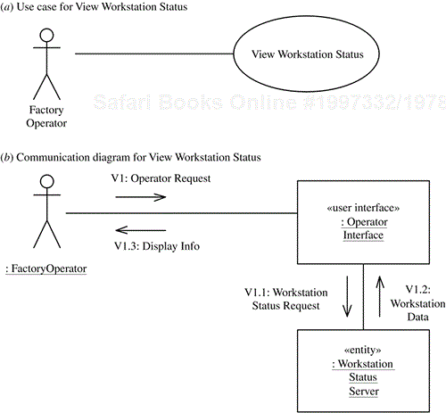
As an example of using a communication diagram to depict the objects that participate in a use case, consider the View Workstation Status use case shown in Figure 7.1, in which a factory operator views the status of one or more factory workstations (Figure 7.1a). The communication diagram for this simple use case consists of only two objects: a client object and a server object. The client object is a user interface object: Operator Interface. The server object is an entity object: Workstation Status Server.
The communication diagram for this use case depicts the client object, Operator Interface, making a request to the server object, Workstation Status Server (see Figure 7.1b). The message sequence description is as follows (see Section 7.5 for an explanation of message numbering):
V1: The operator requests a workstation status service—for example, to view the status of a factory workstation.
V1.1: The
Operator Interfaceobject sends a workstation status request to theWorkstation Status Serverobject.V1.2:
Workstation Status Serverresponds—for example, with the requested workstation status data.V1.3:
Operator Interfacedisplays the workstation status information to the operator.
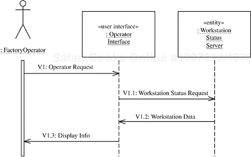
The interaction among objects can also be shown on a sequence diagram, which shows object interactions arranged in time sequence. A sequence diagram shows the objects participating in the interaction and the sequence in which messages are sent. Sequence diagrams and communication diagrams depict similar (although not identical) information, but in different ways. Usually either communication diagrams or sequence diagrams are used to describe a system, but not both. Sequence diagrams have been substantially enhanced in UML 2.0, although only the UML 1.x subset is used in this chapter.
Because the sequence diagram shows the order of messages sent sequentially from the top to the bottom of the diagram, numbering the messages is not necessary. In the following example, however, the messages on the sequence diagram are numbered to show their correspondence to the communication diagram.
An example of a sequence diagram for the View Workstation Status use case is shown in Figure 7.2. This sequence diagram conveys the same information as the communication diagram shown in Figure 7.1. The messages are numbered on this diagram to show the correspondence with the communication diagram. In fact, the message sequence description given in the previous section is applicable to both the sequence diagram and the communication diagram.
Note that in the analysis phase, no decision is made about whether an object is active or passive, so no assumptions should be made about object activation. Consequently, the object lifeline is always shown as a dashed line in the analysis model. On the other hand, the lifeline for the actor is always shown as an activation (double line), because it is assumed that the actor is active.
Either a sequence diagram or a communication diagram can be used to depict the object interaction and sequence of messages passed among objects. The sequence diagram clearly shows the order in which messages are passed between objects, but seeing how the objects are connected to each other is difficult. The communication diagram shows the layout of the objects—in particular, how the objects are connected to each other. The message sequence is shown on both diagrams. Because the message sequence depicted on the communication diagram is less readily visible than on the sequence diagram, the message sequence is numbered. However, even with the message numbering on the communication diagram, it sometimes takes longer to see the sequence of messages. On the other hand, if an interaction involves many objects, a sequence diagram also becomes difficult to read. The diagram might have to be shrunk to fit on a page, or it might span several pages.
In the PLUS method, communication diagrams are generally preferred over sequence diagrams—for several reasons. First, an impact analysis of the effect of features on the object interactions can be clearly depicted on communication diagrams. Second, an important step in the transition from analysis to design is the integration of the communication diagrams to create feature-based communication diagrams (as described in Chapter 9) and the software architecture of the system (as described in Chapter 11). This integration is much easier with communication diagrams than with sequence diagrams. If the analysis started with sequence diagrams, it would be necessary to convert each sequence diagram to a communication diagram before the integration could be done. Sometimes, however, the sequence diagram is very helpful—in particular, for very complex interactions and for timing diagrams in real-time applications (Gomaa 2000).
A scenario is one specific path through a use case. Thus a particular message sequence depicted on an interaction diagram actually depicts a scenario and not a use case. To show all the alternatives through a use case, development of more than one interaction diagram is often necessary.
By using conditions, it is possible to depict alternatives on an interaction diagram and hence to depict the whole use case on a single interaction diagram. However, such comprehensive interaction diagrams are usually more difficult to read. In practice, depicting an individual scenario on an interaction diagram is usually clearer.
The two forms of an interaction (sequence or communication) diagram are the generic form (also referred to as descriptor form) and the instance form. The instance form describes a specific scenario in detail, depicting one possible sequence of interactions among object instances. The generic form describes all possible interactions in which the objects might participate, so it can include loops, branches, and conditions. The generic form of an interaction diagram can be used to describe both the main sequence and the alternatives of a use case. The instance form is used to depict a specific scenario, which is one instance of the use case. Using the instance form might require several interaction diagrams to depict a given use case, depending on how many alternatives are described in the use case.
For all but the simplest use cases, an interaction diagram is usually much clearer when it depicts an instance form rather than a generic form of interaction. It can rapidly become too complicated if several alternatives are depicted on the same diagram.
In the instance form of the sequence diagram, time moves down the page. In the generic form—with loops, branches, and conditions—this is no longer the case. Thus, with the generic form one of the main benefits of using sequence diagrams is lost.
The sequence and communication diagrams shown in this chapter all use the instance form of interaction diagram. The generic form of communication diagram is used for feature-based communication diagrams in Chapter 9 and to depict the software architecture in Chapter 11. There are some differences in notation for the generic form, which will be pointed out in Chapter 9.
In single systems, every use case is required. In software product lines, however, use cases are categorized as kernel, optional, or alternative. A given member of the product line needs all the kernel use cases but only some of the optional and/or alternative use cases. For software product lines, it is necessary to perform dynamic modeling on all the use cases—whatever their reuse category—in order to determine what objects are needed for each use case and how they interact with each other.
As one would do for single systems, develop at least one communication diagram for each use case. Communication diagrams are categorized as kernel, optional, or alternative, corresponding to the reuse category of the use cases for which they are developed. Variant communication diagrams can also be developed to show the impact of use case variation points.
In addition, it is possible to develop feature-based communication diagrams—that is, a communication diagram for each functional feature. This approach is useful when use cases are reused together and hence combined into a feature, for which a feature-based communication diagram is developed, as described in Chapter 9.
Evolutionary dynamic analysis is an iterative strategy to help determine how the analysis model objects interact with each other to support the use cases. Dynamic analysis is carried out for each use case. A first attempt is made to determine the objects that participate in a use case, using the object structuring criteria described in Chapter 6. Then the way in which these objects collaborate to execute the use case is analyzed. This analysis might show a need for additional objects and/or additional interactions to be defined.
Given that the use cases have been categorized as kernel, optional, or alternative, the evolutionary dynamic analysis strategy starts with the kernel first approach (described in Section 7.3), followed by the product line evolution approach (described in Section 7.4). In other words, the strategy starts with the kernel use cases followed by the optional and alternative use cases. Furthermore, the order of developing the object communication diagrams follows the feature dependency hierarchy, as described in Chapter 5. This means that when a communication diagram is developed, it can assume the existence of objects supporting prerequisite features and use cases.
Dynamic analysis can be either state-dependent or non-state-dependent, depending on whether the object communication is state-dependent. This chapter describes non-state-dependent dynamic analysis. State-dependent dynamic analysis is described in Chapter 8.
With the kernel first approach, the dynamic analysis is carried out for the kernel use cases, which are the use cases that are needed by every member of the software product line. The kernel use cases define the kernel of the product line, which is also referred to as the kernel system. Dynamic analysis for the kernel system is similar to dynamic analysis for a single system. Thus communication diagrams for the kernel system, referred to as kernel communication diagrams, are similar to communication diagrams for a single system. Only kernel objects participate in kernel communication diagrams, except when default objects are also needed, as will be described here.
The kernel system is a minimal member of the product line. In some product lines the kernel system consists of only the kernel objects. For other product lines, some objects may be needed in addition to the kernel objects. This can happen when there are alternative use cases, one of which must be selected. In that case, some product line members consist of the kernel system plus objects from one or other of the use cases, but not the kernel system by itself. Objects other than the kernel objects may also be needed when there is a variation point in a kernel use case that necessitates the inclusion of an alternative object. For the kernel system to be a complete system, it might be necessary to include certain default objects or to select one (or more) objects from a group(s) of alternatives. In this situation, the kernel system consists of the kernel objects together with the default objects.
The main steps in the non-state-dependent kernel first approach are as follows: Start with a kernel use case and consider each interaction between the primary actor and the kernel system. Start by developing the communication for the scenario described in the main path of the use case. (The actor starts the interaction with the kernel system through an external event. The sequence of external events generated by the actor is described in the use case.) Consider each interaction in sequence, as follows:
Determine interface object(s). Consider the actor (or actors) that participates in the use case; determine the external objects (external to the system) through which the actor interfaces with the system and the software internal objects that receive the actor's inputs.
Start by considering the events generated by the external objects that interface to the system and participate in the use case. For each external event, consider the software objects required to process the event. An interface object is needed to receive the external event from the external environment. On receipt of the external input, the interface object does some processing and typically sends a message to an internal object.
Determine internal objects. Start with the main sequence of the use case. Using the object structuring criteria, make a first attempt at determining the internal objects that participate in the use case, such as control or entity objects.
Determine object communication. For each external event generated by an actor, consider the communication required between the interface object that receives the event and the subsequent objects—entity or control objects—that cooperate in processing this event. Draw a communication diagram or sequence diagram showing the objects participating in the use case and the sequence of messages passing between them. Repeat this process for each subsequent interaction between the actor(s) and the system. As a result, additional objects may be required to participate, and additional message communication, along with message sequence numbering, will need to be specified.
Consider alternative sequences. Consider the different alternatives, such as error handling, that the use case needs to address. Then consider what objects need to be involved in executing the alternative branches.
Consider the variation points. Consider what objects are needed and what message sequences are needed to address each variation point. Variant communication diagrams are developed as described in Section 7.4.3.
As an example of the non-state-dependent kernel first approach, consider the Factory Operator use cases from the factory automation product line. These use cases are kernel use cases. Kernel objects depicted include Workstation Status Server, Alarm Handling Server, and Workstation Controller. For each kernel use case, a kernel communication diagram is developed, such as the one for View Workstation Status shown in Figure 7.1b.
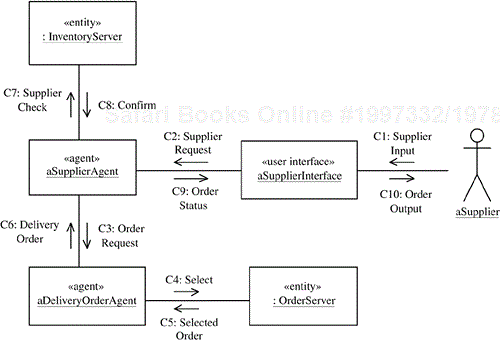
As another example of the non-state-dependent kernel first approach, consider a kernel use case from the electronic commerce software product line. The Process Delivery Order use case is kernel because it is used in all member electronic commerce systems. In this use case, the supplier starts working on a customer's delivery order.
First the supplier must check that sufficient inventory exists to satisfy the order. From an object structuring point of view, there is a user interface object (Supplier Interface), and there are two entity objects (Inventory Server and Order Server). In addition, this case study adopts a software agent solution, so there are two agent objects: Supplier Agent (which acts on behalf of the supplier) and Delivery Order Agent (which acts on behalf of the delivery order server, interacting with other software agents, including Supplier Agent).
Because these objects participate in a kernel use case, they will later be categorized as kernel objects from a reuse perspective, as described in Chapter 9. Note that although a first cut at object reuse categorization might determine an object as kernel, subsequent dynamic modeling might determine that the object is really a default or optional object. For this reason, object reuse categorization is deferred until all dynamic modeling has been completed.
In the communication diagram for the Process Delivery Order use case (Figure 7.3), Supplier Agent queries Delivery Order Agent for a new delivery order from Order Server; the agent selects a delivery order. The Supplier Agent checks the inventory maintained by Inventory Server and then displays the order and inventory information to the supplier via Supplier Interface.
The software product line evolution approach starts with the kernel communication diagrams developed with the kernel first approach, as described in Section 7.3. The product line evolves with the addition of the optional and alternative use cases. With the software product line evolution approach, optional and alternative communication diagrams are developed to depict the objects that participate in the optional and alternative use cases, as well as the sequence of object interactions.
The approach for developing individual optional or alternative communication diagrams is similar to that used for the kernel communication diagrams. It is to be expected that new objects will appear on these additional communication diagrams, which are then categorized as optional or variant objects.
There are two main types of evolution to consider. In the first case, one or more variation points within a use case need to be considered. In that situation, the communication diagram that needs to be developed is a modified version of the original communication diagram, which is referred to as a variant communication diagram. In the second case, there are separate optional and/or alternative use cases, for which separate optional and/or alternative communication diagrams need to be developed. This section describes the development of the optional and alternative communication diagrams for the separate use cases before describing the variant communication diagrams.
For optional use cases, product line evolution consists of developing optional communication diagrams in which optional and possibly variant objects participate. The approach is to develop a separate optional communication diagram for each optional use case, depicting the optional and variant objects that participate in that use case. In some cases these optional and variant objects might interact with kernel objects in order to execute the use case. In such cases, the kernel objects involved are also depicted on the optional communication diagram.
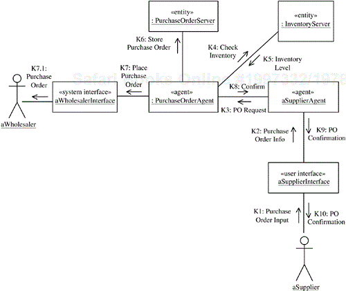
Consider the optional communication diagram (Figure 7.4) for an optional use case, Prepare Purchase Order, which is also from the electronic commerce software product line. This use case is optional because for some members, purchase orders are handled by the product line system, whereas for other members, purchase orders are handled by an external system. The objects required for this communication include Supplier Interface, Inventory Server, and Supplier Agent. These objects were previously categorized as kernel objects because they participate in the kernel use case Process Delivery Order.
Three additional objects are needed to handle a purchase order: (1) an entity object, Purchase Order Server; (2) another software agent, Purchase Order Agent; and (3) a system interface object, Wholesaler Interface. These objects will be categorized as optional objects from a reuse perspective (as described in Chapter 9) because they participate only in optional use cases. The role of Purchase Order Agent is to make sure that the purchase order is created and sent to the wholesaler, to handle the purchase order when it is delivered by updating inventory and updating the purchase order, and to send an electronic payment request to the supplier's bank, as described in Chapter 14.
Alternative communication diagrams are developed for alternative use cases that occur in different members of the product line. Because alternative use cases are mutually exclusive, the alternative communication diagrams are also mutually exclusive. This means that the alternative communication diagrams can never be part of the same product line member. However, they will be in different product line members.
For each alternative use case, a separate alternative communication diagram is developed to depict the variant objects and/or optional objects that participate in that use case, and possibly some kernel objects. Consider also an example from the electronic commerce software product line in which alternative use cases support two mutually exclusive member systems: business-to-consumer (B2C) applications and business-to-business (B2B) applications.
The Bill Customer use case is an example of a B2C use case in which the home customer is billed directly for a purchase. The alternative is the Send Invoice B2B use case for business customers who receive invoices for their purchases. The communication diagram for Bill Customer (Figure 7.5) involves three kernel objects from the kernel use case: Supplier Interface, Delivery Order Agent, and Supplier Agent. In addition, three other objects are required: (1) Customer Account Server, to encapsulate home customer accounts, and (2) Billing Agent, which is responsible for making sure that customer accounts are first validated and later billed by sending payment requests to (3) Authorization Center Interface. These new objects will be categorized as optional objects from a reuse perspective. Although these objects participate in an alternative use case, they are categorized as optional (and not variant) because their roles are unique in the product line and there are no other variant objects. Chapter 9 will provide more details on object categorization for reuse.
For a use case that has one or more variation points (which correspond to features) specified within it, a different approach is used. Instead of developing a different communication diagram for each use case, the approach is to consider the impact of each variation point on the original communication diagram for the use case and develop optional branches on that diagram. This section describes the approach in terms of variation points to a kernel use case. However, the approach is the same regardless of whether the use case is kernel, optional, or alternative.
Consider a kernel use case with variation points. First the kernel communication diagram is developed as described in Section 7.3. Next the impact of each variation point on the kernel communication diagram is analyzed by the development of optional branches on the kernel communication diagrams corresponding to optional interactions. The optional branches depict optional and/or variant objects and the interaction between these objects. These optional and variant objects can also interact with kernel objects. For this reason the variant communication diagram also depicts the interaction of the objects in the optional branch with the kernel objects.
There are two ways to depict a variant communication diagram. The first is to show the optional branches added to the kernel communication diagram. The other approach is just to show the changes to the communication diagram—in other words, just to depict the newly added optional and/or variant objects, as well as the objects affected by the variation point.
Messages on a communication diagram or sequence diagram are given message sequence numbers. This section provides some guidelines for numbering message sequences. These guidelines follow the general UML conventions; however, they have been extended to address concurrency, alternatives, and large message sequences better. These conventions are followed in the example of evolutionary dynamic modeling for the microwave oven product line given in Section 7.6 and in the case studies in Chapters 13, 14, and 15. This section can be skipped at first reading.
A message label on a communication or sequence diagram has the following syntax (only those parts of the message label that are relevant in the analysis phase are described here):
[sequence expression]: Message Name (argument list)
where the sequence expression consists of the message sequence number and an indicator of recurrence.
Message sequence number. The message sequence number is described as follows: The first message sequence number represents the event that initiates the message sequence depicted on the communication diagram. Typical message sequences are 1, 2, 3, …; A1, A2, A3, …
A more elaborate message sequence can be depicted with the Dewey classification system, such that A1.1 precedes A1.1.1, which in turn precedes A1.2. In the Dewey system, the a typical message numbering sequence would be A1, A1.1, A1.1.1, A1.2.
Recurrence. The recurrence term is optional and represents conditional or iterative execution only on communication diagrams. It is no longer used on UML 2.0 sequence diagrams, because UML 2.0 uses a different notation for iterative and conditional execution. The recurrence term represents zero or more messages that are sent, depending on the conditions being met. There are two choices:
* [iteration-clause]. An asterisk (*) is added after the message sequence number to indicate that more than one message is sent. The optional iteration clause is used to specify repeated execution, such as [j := 1,n]. An example of an iteration by putting an asterisk after the message sequence number is 3*.
[condition-clause]. A condition is specified in square brackets to indicate a branch condition. The optional condition clause is used for specifying branches—for example, [x < n]—meaning that the message is sent only if the condition is true. Examples of conditional message passing by showing a condition after the message sequence number are 4[x < n] and 5[Normal]. In each case, the message is sent only if the condition is true.
Message name. The message name is specified.
Argument list. The argument list of the message is optional and specifies any parameters sent as part of the message.
There can also be optional return values from the message sent. However, it is recommended to use only simple messages during the analysis phase, in which case there are no return values, and to postpone to the design phase the decision about which kind of message to use.
On a communication diagram supporting a use case, the sequence in which the objects participate in each use case is described and depicted by message sequence numbers. A message sequence number for a use case takes the following form:
[first optional letter sequence] [numeric sequence] [second optional letter sequence]
The first optional letter sequence is an optional use case ID and identifies a specific concrete use case or abstract use case. The first letter is an uppercase letter and might be followed by one or more upper- or lowercase letters if a more descriptive use case ID is desired.
In an interactive system with several external inputs from the actor, it is often helpful to include a numeric sequence—that is, to number the external events as whole numbers followed by decimal numbers for the ensuing internal events. For example, if the actor's inputs were designated as A1, A2, and A3, the full message sequence depicted on the communication diagram would be A1, A1.1, A1.2, A1.3, …, A2, A2.1, A2.2, …, and A3, A3.1, A3.2, ….
An example is V1, where the letter V identifies the use case and the number identifies the message sequence within the communication diagram supporting the use case. The object sending the first message—V1—is the initiator of the use case–based communication. In a concrete use case, the initiator should be an actor; in an abstract use case, however, the initiator can be an object. Thus, in the communication and sequence diagram examples in Figures 7.1 and 7.2, respectively, the input from the actor is V1. Subsequent message numbers following this input message are V1.1, V1.2, and V1.3. If the dialog were to continue, the next input from the actor would be V2.
The second optional letter sequence is used to depict special cases of branches—either concurrent or alternative—in the message sequence numbering.
Concurrent message sequences may also be depicted on a communication diagram. A lowercase letter represents a concurrent sequence; in other words, sequences designated as A3 and A3a would be concurrent sequences. For example, the arrival of message A2 at an object X might result in the sending of two messages from object X to two objects Y and Z, which could then execute in parallel. To indicate the concurrency in this case, the message sent to object Y would be designated as A3; and the one to object Z, as A3a. Subsequent messages in the A3 sequence would be A4, A5, A6, …, and subsequent messages in the independent A3a sequence would be A3a.1, A3a.2, A3a.3, and so on. Because the sequence numbering is more cumbersome for the A3a sequence, use A3 for the main message sequence and A3a and A3b for the supporting message sequences. An alternative way to show two concurrent sequences is to avoid A3 altogether and use the sequence numbers A3a and A3b; however, this can lead to a more cumbersome numbering scheme if A3a initiates another concurrent sequence, so the former approach is preferred.
Alternative message sequences are depicted with the condition indicated after the message. An uppercase letter is used to name the alternative branch. For example, the main branch may be labeled 1.4[Normal], and the other, less frequently used branch could be named 1.4A[Error]. The message sequence numbers for the normal branch would be 1.4[Normal], 1.5, 1.6, and so on. The message sequence numbers for the alternative branch would be 1.4A[Error], 1.4A.1, 1.4A.2, and so on.
Examples of concurrent and alternative message sequences are given in the following example and in the case studies.
This section gives an example of evolutionary dynamic analysis, which starts with the kernel first approach and continues with the product line evolution approach. Evolutionary dynamic analysis is used in the microwave oven product line (see Chapter 13), where several scenarios involving optional objects are depicted. The communication diagrams for these scenarios depict variations on the kernel communication diagram resulting from the presence of variation points in the kernel use case Cook Food.
With the kernel first approach, the objective is first to determine objects in the kernel use case. These objects consist of kernel objects—that is, objects used by every member of a product line—and default objects. A default object is one of a group of variant objects in the product line. The default object is the variant object that is automatically selected for a given member of the product line unless an alternative user selection is made.
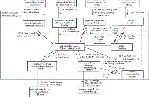
Several kernel objects are required for the Cook Food use case, as depicted on the kernel communication diagram (Figure 7.6) for the use case. These include Door Sensor Interface, Weight Sensor Interface, and Keypad Interface, which are kernel input device interface objects. Heating Element Interface and Display Interface are kernel output device interface objects. Oven Timer is the software timer object. There is an entity object to store microwave oven data, such as the cooking time, which is called Oven Data. Finally, because of the complex sequencing and control required for the oven, a state-dependent control object is required, Microwave Oven Control, which executes the statechart for the oven.
On the basis of the object structuring criteria described in Chapter 6, the kernel objects are categorized as follows:
Input device interface objects:
Door Sensor InterfaceWeight Sensor InterfaceKeypad Interface
Output device interface objects:
Heating Element InterfaceDisplay Interface
Microwave Oven ControlOven Timer
Oven DataDisplay Prompts
In addition, the following default objects are determined from the kernel use case and variation points:
Boolean Weight Sensor InterfaceOne-level Heating Element InterfaceOne-line Display InterfaceEnglish Display Prompts
The kernel objects, together with the default objects already named, constitute the kernel system.
After the kernel first approach is applied, the product line evolution approach is applied to determine the impact of optional and alternative features on the kernel communication diagram. The approach, which is called feature-based impact analysis, systematically analyzes the impact of each feature and variation point on the kernel communication diagram
Consider the impact of the use case variation points. First consider a variation point, which represents an optional feature—for example, the Beeper variation point. This optional feature requires the addition of the Beeper Interface optional object to the Microwave Oven Kernel communication diagram, as shown in Figure 7.7. This variant communication diagram shows the addition of the optional Beeper Interface object and the optional Beeper external hardware object, as well as the modified Microwave Oven Control object, which has to send the Beep message (message 8.4a) to the Beeper Interface object, which in turns sends Beep Output (message 8.4a.1) to the Beeper external output device. Because this is a conditional message, it is guarded by a Boolean feature condition [beeper], which is true only if the feature is provided. This means that the Beep message is sent only if the [beeper] condition is true—that is, if the microwave oven system provides this feature. Note that, by convention, the first letter of a feature condition is lowercase to distinguish it from other types of conditions.
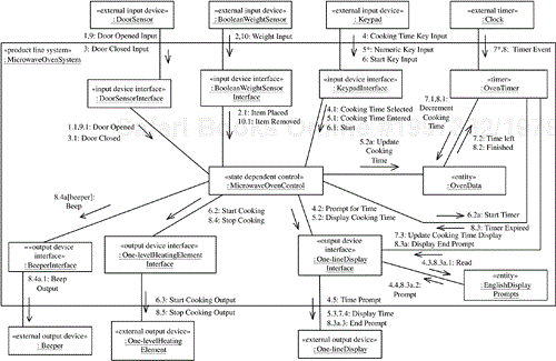
Figure 7.7. Variant communication diagram depicting the impact of the Beeper variation point and optional feature
Another way of depicting the same information is to show only the branch that has changed on the communication diagram. This branch consists of the Microwave Oven Control, Beeper Interface, and Beeper objects, starting with the Beep message, as depicted in Figure 7.8. Because this diagram shows the impact of the variation point much more clearly than Figure 7.7 does, it is the preferred approach and will be used in future. An alternative, however, is to use color coding—that is, to show the complete communication diagram, with the affected objects in a different color.
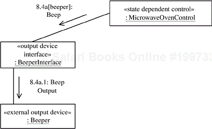
Figure 7.8. Variant Beeper branch depicting the impact of the Beeper variation point and optional feature
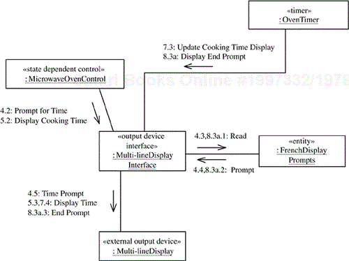
Now consider the situation in which the use case variation point represents an alternative feature; for example, Display Language is French instead of English. In this case, a variant object, French Display Prompts, replaces a default object, English Display Prompts, as shown in Figure 7.9. The impact of another alternative feature, Display Unit = Multi-line Display (also shown in Figure 7.9), results in the variant output device interface object Multi-line Display Interface replacing the default One-line Display Interface object. More-complicated alternatives might lead to the development of alternative branches on kernel communication diagrams, showing how the variant and optional objects interact with kernel objects.
Variation points and features can affect the kernel system in different ways. Consider the impact of variation points and features through the following examples:
Impact of variation points that lead to new concurrent actions. The impact of the
Beeperfeature described in the preceding section is to result in the newBeeper Interfaceobject andBeeperexternal object (see Figures 7.7 and 7.8), a newBeeperbranch on the communication diagram, and a change toMicrowave Oven Control, which has to send aBeepmessage toBeeper Interface. BecauseMicrowave Oven Controlsends theBeepmessage at the same time as it sends theStop Cookingmessage, the convention for concurrent message sequences (see Section 7.5.3) is used. Thus theBeepmessage, depicted as 8.4a:Beep, is sent toBeeper Interfaceat the same time as the message 8.4:Stop Cookingis sent toHeating Element Interface. TheBeepmessage has a ripple effect because 8.4a:Beepis followed byBeeper Interfacesending the 8.4.a.1:Beep Outputmessage to the externalBeeperobject.Impact of variation points that lead to additional sequential actions. Some variation points lead to optional sequential actions that need to be inserted into the message sequence depicted on the kernel communication diagrams. The
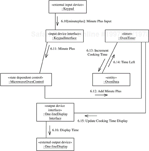
Minute Plusfeature allows the user to press a Minute Plus key either before or during cooking. In the latter case, a minute is added to the cooking time and cooking continues without interruption. On the kernel communication diagram, message 6 is theStart Key Inputmessage from the externalKeypadobject to start cooking, which leads to a sequence ending in 6.3:Start Cooking Outputto the externalHeating Elementobject (see Figure 7.6). The next message on the kernel communication diagram is 7*:Timer Event. Because the effect of theMinute Plusfeature is that the externalKeypadobject sendsKeypad Interfacea message between messages 6.3 and 7, the convention is to show the additional key press as 6.10[minuteplus]:Minute Plus Input, as shown in Figure 7.10. The “6.10” indicates that this message is sent between 6.3 and 7. The message sequence number 6.10 is preferred over 6.4 to delineate between the 6:Start Key Inputsequence and the 6.10:Minute Plus Inputsequence. The 6.10 sequence is followed by 6.11, 6.12, and so on. The [minuteplus] condition is a feature condition, which indicates that the 6.10[minuteplus] sequence is a conditional sequence, taking place only when the Boolean feature condition [minuteplus] is true.Impact of variation points that lead to alternative actions. Continuing with the
Minute Plusfeature, a second option is for the Minute Plus key to be pressed before cooking has started, as shown in Figure 7.11. In this case, cooking is started and will stop after a minute (unless another external event takes place first). Pressing Minute Plus in this situation takes the place of pressing three other types of keys shown in Figure 7.6: the Cooking Time key (message 4:Cooking Time Key Input), the numeric keys (message 5*:Numeric Key Input), and the Start key (message 6:Start Key Input). Because pressing Minute Plus in this situation is an alternative sequence, the message sequence numbering starts with 4M[minuteplus]:Minute Plus Input. The 4M indicates that this is an alternative sequence. As in the previous example, the [minuteplus] condition is a feature condition indicating that this is a conditional sequence.Impact of new features resulting from optional use cases. The
TOD Clockfeature is captured by two use cases—Set Time of DayandDisplay Time of Day—as described in Chapter 5. Each of these use cases is realized as depicted on a communication diagram. In this situation, it is more concise to show the impact of both use cases on the same communication diagram, as Figure 7.12 does. However, it is important to clearly distinguish between the message sequences depicting the realization of each use case. The following measures help make this distinction:The message sequence for the
Set Time of Daycommunication is prefixed by the letter C, starting with C1:TOD Clock Key Inputsent byKeypadtoKeypad Interface.The message sequence for the
Display Time of Daycommunication is prefixed by the letter T, starting with T1*:Timer Eventsent by the externalClockobject toTOD Timer.
This chapter described dynamic modeling for software product lines. The dynamic model addresses interaction between objects, describing how objects interact with each other; as well as within objects, describing how an active state-dependent object is defined by means of a finite state machine and depicted as a statechart. The state-dependent aspect of dynamic modeling involving finite state machines and statecharts is described in Chapter 8.
This chapter briefly described dynamic modeling in single systems before describing dynamic modeling for software product lines. It then described how the kernel first approach is used to determine the interaction among kernel objects, which realize the kernel use cases. The discussion continued with an explanation of how the product line evolution approach is subsequently used to determine the interaction among optional and variant objects. Optional communication diagrams are developed to realize the optional use cases, while alternative communication diagrams are developed to realize the alternative use cases; variant communication diagrams are developed to depict the impact of variation points in use cases.
Chapter 9 will describe how communication diagrams are integrated to form feature-based communication diagrams. Chapter 10 will describe software architectural communication patterns using communication diagrams. Chapter 11 will describe how communication diagrams can be used to depict software architectures.

