
This chapter describes key concepts in the software design of software product lines, as well as important concepts for developing the architecture of these systems. First, object-oriented concepts are introduced, including a description of objects and classes, as well as a discussion of the role of information hiding in object-oriented design and an introduction to the concept of inheritance. Next the concurrent processing concept is introduced, as well as the concept of concurrent objects in concurrent applications. The chapter also describes the underlying technologies for designing software product lines, including component-based systems and technologies. Examples in this chapter are described in UML. An overview of the UML notation is given in Appendix A.
Section 2.1 provides an overview of object-oriented concepts. Section 2.2 describes information hiding. Section 2.3 describes the relationships between classes, including associations, whole/part relationships, and generalization/specialization relationships. Section 2.4 provides an overview of dynamic modeling. Section 2.5 discusses the differences between sequential and concurrent applications and provides an overview of concurrent objects. Finally, Section 2.6 gives an overview of software architecture and the main characteristics of component-based systems.
The term object-oriented was first introduced in connection to object-oriented programming and Smalltalk (Goldberg and Robson 1983), although the object-oriented concepts of information hiding and inheritance have earlier origins. Information hiding and its use in software design date back to Parnas (1972), who advocated using information hiding as a way to design modules that were more self-contained and hence could be changed with little or no impact on other modules. The concepts of classes and inheritance were first used in Simula 67 (Dahl and Hoare 1972), but only with the introduction of Smalltalk did they start gaining widespread acceptance.
Object-oriented concepts are considered important in product line development because they address fundamental issues of adaptation and evolution. Because the object-oriented model of software development is considered especially conducive to evolution and change, the product line modeling approach takes an object-oriented perspective. The goal is to apply object-oriented concepts and extend them to modeling software product lines.
An object is a real-world physical or conceptual entity that provides an understanding of the real world and hence forms the basis for a software solution. A real-world object can have physical properties (they can be seen or touched); examples are a door, motor, or lamp. A conceptual object is a more abstract concept, such as an account or transaction.
Object-oriented applications consist of objects. From a design perspective, an object groups both data and procedures that operate on the data. The procedures are usually called operations or methods. Some approaches, including the UML notation, refer to the operation as the specification of a function performed by an object and the method as the implementation of the function (Rumbaugh et al. 2005). In this book the term operation refers to both the specification and the implementation, in common with Gamma et al. 1995, Meyer 1997, and others.
The signature of an operation specifies the operation's name, the operation's parameters, and the operation's return value. An object's interface is the set of operations it provides, as defined by the signatures of the operations. An object's type is defined by its interface. An object's implementation is defined by its class. Thus, Meyer refers to a class as an implementation of an abstract data type (Meyer 1997).
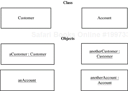
An object (also referred to as an object instance) is a single “thing”—for example, John's car or Mary's account. A class (also referred to as an object class) is a collection of objects with the same characteristics; for example, Account, Employee, Car, or Customer. Figure 2.1 depicts a class Customer and two objects: a Customer and another Customer,[1] which are instances of the class Customer. The objects an Account and another Account are instances of the class Account.
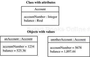
An attribute is a data value held by an object in a class. Each object has a specific value of an attribute. Figure 2.2 shows a class with attributes. The class Account has two attributes: account Number and balance. Two objects of the Account class are shown: an Account and another Account. Each account has specific values of the attributes. For example, the value of account Number of the object an Account is 1234, and the value of account Number of the object another Account is 5678. The value of balance of the former object is $525.36, and the value of balance of the latter is $1,897.44.
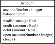
An operation is the specification of a function performed by an object. An object has one or more operations. The operations manipulate the values of the attributes maintained by the object. Operations may have input and output parameters. All objects in the same class have the same operations. For example, the class Account has the operations read Balance, credit, debit, open, and close. Figure 2.3 shows the Account class with its operations.
An object is an instance of a class. Individual objects are instantiated as required at execution time. Each object has a unique identity, which is the characteristic that distinguishes it from other objects. In some cases, this identity may be an attribute (e.g., an account number or a customer name), but it does not need to be an attribute. Consider two blue balls: They are identical in every respect; however, they have different identities.
Information hiding is a fundamental software design concept relevant to the design of all software systems. Early systems were frequently error-prone and difficult to modify because they made widespread use of global data. Parnas (1972, 1979) showed that by using information hiding, developers could design software systems to be substantially more modifiable by greatly reducing or—ideally—eliminating global data. Parnas advocated information hiding as a criterion for decomposing a software system into modules. Each information hiding module should hide a design decision that is considered likely to change. Each changeable decision is called the secret of the module. With this approach, the goal of design for change could be achieved.
Information hiding is a basic concept of object-oriented design. Information hiding is used in designing the object, in particular when deciding what information should be visible and what information should be hidden. Aspects of an object that need not be visible to other objects are hidden. Hence, if the internals of the object change, only this object is affected. The term encapsulation is also used to describe information hiding by an object.
With information hiding, the information that could potentially change is encapsulated (i.e., hidden) inside an object. The information can be externally accessed only indirectly by the invocation of operations—access procedures or functions—that are also part of the object. Only these operations can access the information directly. Thus the hidden information and the operations that access it are bound together to form an information hiding object. The specification of the operations (i.e., the name and the parameters of the operations) is called the interface of the object. The object's interface is also referred to as the abstract interface, virtual interface, or external interface. The interface represents the visible part of the object—that is, the part that is revealed to users of the object. Other objects access the hidden information indirectly by calling the operations provided by the object.
A potential problem in application software development is that an important data structure, one that is accessed by several objects, might need to be changed. Without information hiding, any change to the data structure is likely to require changes to all the objects that access that data structure. Information hiding can be used to hide the design decision concerning the data structure, its internal linkage, and the details of the operations that manipulate it. The information hiding solution is to encapsulate the data structure in an object. The data structure is accessed only directly by the operations provided by the object.
Other objects may only indirectly access the encapsulated data structure by calling the operations of the object. Thus, if the data structure changes, the only object affected is the one containing the data structure. The external interface supported by the object does not change; hence the objects that indirectly access the data structure are not affected by the change. This form of information hiding is called data abstraction.
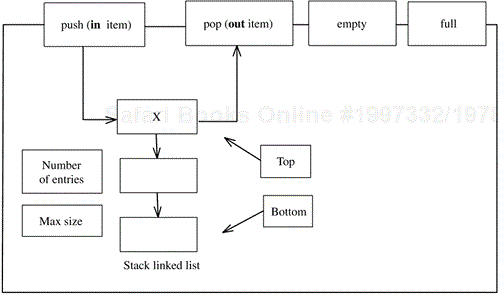
An example of information hiding is a stack object. The information hiding solution is to hide the representation of the stack—for example, an array—from the objects needing to access it. An information hiding object—the stack object—is designed as follows (see Figure 2.4):
A set of operations is defined to manipulate the data structure. In the case of the stack, typical operations are
push,pop,full, andempty.The data structure is defined. In the case of the stack, for example, a one-dimensional array is defined. A variable is defined to refer to the top of the stack, and another variable has the value of the size of the array.
Other objects are not permitted to access the data structure directly. They can access the data structure only indirectly by calling the object's operations.
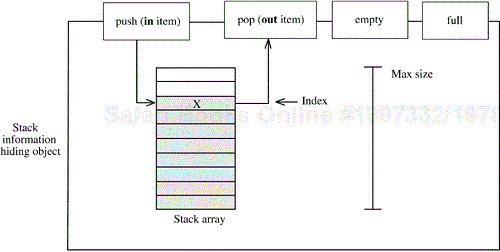
Note: This diagram does not use the UML notation.
Figure 2.4. Example of a stack information hiding object implemented as an array
Now assume that the design of the stack is changed from an array to a linked list. In the information hiding solution, in addition to the internal stack data structure changing drastically, the internals of the information hiding object's operations have to change because they now access a linked list instead of an array (see Figure 2.5). However, the external interface of the object, which is what is visible to the other objects, does not change. Thus the objects that use the stack are not affected by the change; they continue to call the object's operations without even needing to be aware of the change.
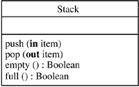
The same concepts can be applied to designing a stack class, which is a template for creating stack objects. A stack class is defined as containing the data structure to be used for the stack and the operations that manipulate it, as shown in Figure 2.6. Individual stack objects are instantiated as required by the application. Each stack object has its own identity. It also has its own local copy of the stack data structure, as well as a local copy of any other instance variables required by the stack's operations.
There are three main types of relationships between classes: associations, whole/part relationships, and generalization/specialization relationships. Sections 2.3.1 through 2.3.3 describe each type in turn.
An association is a static, structural relationship between two or more classes. The multiplicity of an association specifies how many instances of one class may relate to a single instance of another class. The multiplicity of an association may be
One-to-one (1..1). In a one-to-one association between two classes, the association is one-to-one in both directions.
One-to-many (1..*). In a one-to-many association, two classes have a one-to-many association in one direction and a one-to-one association in the opposite direction.
Numerically specified (m..n). A numerically specified association is an association that refers to a specific range of numbers.
Optional (0..1). In an optional association, two classes have a zero-to-one association in one direction and a one-to-one association in the opposite direction. This means that there might not always be a link from an object in one class to an object in the other class.
Many-to-many (*). In a many-to-many association, two classes have a one-to-many association in each direction.
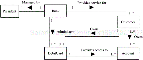
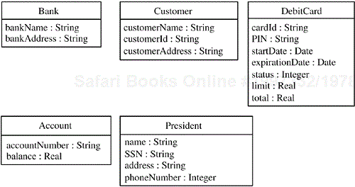
An example of classes and their associations in a banking application is given in Figure 2.7. The Bank class has a one-to-many relationship with the Customer class and the Debit Card class. Customer has a many-to-many relationship with Account; so a customer might have more than one account, and an account could be a joint account belonging to more than one customer. Customer has an optional association with Debit Card; so a given customer might or might not own a debit card, but a debit card must belong to a customer. Bank has a one-to-one relationship with President; so a bank can have only one president, and a president can be president of only one bank. The attributes of these classes are shown in Figure 2.8.
Composition and aggregation are special forms of relationships in which the classes are tightly bound by the whole/part relationship. Both composition and aggregation hierarchies address a class that is made up of other classes.
Composition is a stronger form of aggregation, and an aggregation is stronger than an association. In particular, the composition relationship demonstrates a stronger relationship between the parts and the whole than does the aggregation relationship. A composition is also a relationship among instances. Thus the part objects are created, live, and die together with the whole. The part object can belong to only one whole.
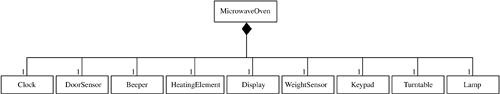
An example of a composition hierarchy is the class Microwave Oven, which represents the whole and is composed of several part classes: Door Sensor, Heating Element, Display, Weight Sensor, and Turntable. There is a one-to-one association between the Microwave Oven composite class and each of the part classes, as shown in Figure 2.9.
The aggregation hierarchy is a weaker form of whole/part relationship. In an aggregation, part instances can be added to and removed from the aggregate whole. For this reason, aggregations are likely to be used to model conceptual classes rather than physical classes. In addition, a part may belong to more than one aggregation.
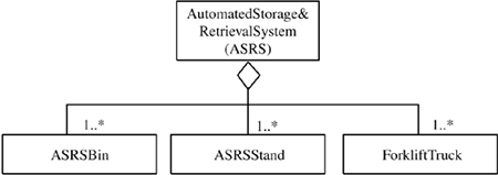
An example of an aggregation hierarchy is the Automated Storage & Retrieval System (ASRS), which consists of one-to-many relationships with ASRS Bin, ASRS Stand, and Forklift Truck (see Figure 2.10). The reason that the ASRS is modeled as an aggregation is that it could be expanded to add more bins, stands, and trucks after it has been created.
Inheritance is a useful abstraction mechanism in analysis and design. Inheritance naturally models objects that are similar in some but not all respects, thus having some common properties but other unique properties that distinguish them. Inheritance is a classification mechanism that has been widely used in other fields. An example is the taxonomy of the animal kingdom, in which animals are classified as mammals, fish, reptiles, and so on. Cats and dogs have common properties that are generalized into the properties of mammals. However, they also have unique properties: A dog barks and a cat mews.
Inheritance is a mechanism for sharing and reusing code between classes. A child class inherits the properties (encapsulated data and operations) of a parent class. It can then adapt the structure (i.e., encapsulated data) and behavior (i.e., operations) of its parent class. The parent class is referred to as a superclass or base class. The child class is referred to as a subclass or derived class. The adaptation of a parent class to form a child class is referred to as specialization. Child classes may be further specialized, allowing the creation of class hierarchies, also referred to as generalization/specialization hierarchies.
Class inheritance is a mechanism for extending an application's functionality by reusing the functionality specified in parent classes. Thus a new class can be incrementally defined in terms of an existing class. A child class can adapt the encapsulated data (referred to as instance variables) and operations of its parent class. It adapts the encapsulated data by adding new instance variables. It adapts the operations by adding new operations or by redefining existing operations. It is also possible for a child class to suppress an operation of the parent; however, such suppression is not recommended, because in that case the subclass no longer shares the interface of the superclass.
Consider the example of bank accounts given in Figure 2.11. Checking accounts and savings accounts have some attributes in common and others that are different. The attributes that are common to all accounts—namely, account Number and balance—are made attributes of an Account superclass. Attributes specific to a savings account, such as cumulative Interest (in this bank, checking accounts do not accumulate any interest), are made attributes of the subclass Savings Account. Attributes specific to a checking account, such as last Deposit Amount, are made attributes of the subclass Checking Account.

For each of the subclasses, new operations are added. For the Savings Account subclass, the new operations are read Cumulative Interest to read cumulative Interest, and add Interest to add the daily interest. For the Checking Account subclass, the new operation is read Last Deposit Amount. This example is treated in more detail in Chapter 9.
Whereas static modeling provides insight into the static structure of a system, dynamic modeling provides a view of a system in which control and sequencing are considered, either within an object (by means of a finite state machine) or among objects (by consideration of the sequence of interactions among them).
To model the sequence of interaction among objects for a particular scenario, it is necessary to define the objects that participate in the scenario, the external object and external event that trigger the scenario, and the subsequent sequence of interactions among the internal objects. If an object's actions are state-dependent, then its sequence of internal states, events, and actions can be modeled with a finite state machine.
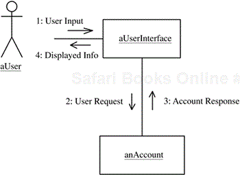
An example of dynamic modeling is given in Figure 2.12, in which a user makes a request to view some account information. The object named a User Interface sends the read request to the object an Account, which responds with the account data. The user interface object then formats and displays the response to the user. The messages are numbered to depict the sequence of message interactions, as shown in the UML communication diagram in Figure 2.12.
An object may be active or passive. Whereas objects are often passive—that is, they wait for another object to invoke an operation and never initiate any actions—some object-oriented methods and languages, such as Ada and Java, support active objects. Active (concurrent) objects execute independently of other active objects.
A sequential application is a sequential program that consists of passive objects and has only one thread of control. When an object invokes an operation in another object, control is passed from the calling operation to the called operation. When the called operation finishes executing, control is passed back to the calling operation. In a sequential application, only synchronous message communication (i.e. procedure call or method invocation) is supported.
In a concurrent application, there are typically several concurrent objects, each with its own thread of control. Asynchronous message communication is supported, so a concurrent source object can send an asynchronous message to a concurrent destination object and then continue executing, regardless of when the destination object receives the message. If the destination object is busy when the message arrives, the message is buffered for the object.
Concurrent objects are also referred to as active objects, concurrent tasks, or threads (Gomaa 2000). A concurrent object (active object) has its own thread of control and can initiate actions that affect other objects. Passive objects have operations that are invoked by concurrent objects. Passive objects can invoke operations in other passive objects. A passive object has no thread of control; thus, passive objects are instances of passive classes. An operation of a passive object, once invoked by a concurrent object, executes within the thread of control of the concurrent object.
A concurrent object represents the execution of a sequential program or a sequential component in a concurrent program. Each concurrent object deals with one sequential thread of execution; thus, no concurrency is allowed within a concurrent object. However, overall system concurrency is achieved by the execution of multiple concurrent objects in parallel. Concurrent objects often execute asynchronously (i.e., at different speeds) and are relatively independent of each other for significant periods of time. From time to time, concurrent objects need to communicate and synchronize their actions.
In the design of concurrent systems, several problems need to be considered that do not arise in the design of sequential systems. In most concurrent applications, concurrent objects must cooperate with each other in order to perform the services required by the application. The following three problems commonly arise when concurrent objects cooperate with each other:
The mutual exclusion problem occurs when concurrent objects need to have exclusive access to a resource, such as shared data or a physical device. A variation on this problem, in which the mutual exclusion constraint can sometimes be relaxed, is the multiple readers and writers problem.
The synchronization problem occurs when two concurrent objects need to synchronize their operations with each other.
The producer/consumer problem occurs when concurrent objects need to communicate with each other in order to pass data from one concurrent object to another. Communication between concurrent objects is often referred to as interprocess communication (IPC).
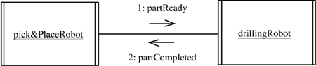
Consider an example of event synchronization from concurrent robot systems. Each robot system is designed as a concurrent object and controls a moving robot arm. A pick-and-place robot brings a part to the work location so that a drilling robot can drill four holes in the part. On completion of the drilling operation, the pick-and-place robot moves the part away.
Several synchronization problems need to be solved here. First, there is a collision zone where the pick-and-place and drilling robot arms could potentially collide. Second, the pick-and-place robot must deposit the part before the drilling robot can start drilling the holes. Third, the drilling robot must finish drilling before the pick-and-place robot can remove the part. The solution is to use event synchronization, as described next.
The pick-and-place robot moves the part to the work location, moves out of the collision zone, and then signals the event part Ready. This signal awakens the drilling robot, which moves to the work location and drills the holes. After completing the drilling operation, the drilling robot moves out of the collision zone and then signals a second event, part Completed, which the pick-and-place robot is waiting to receive. After being awakened, the pick-and-place robot removes the part. Each robot task executes a loop, because the robots repetitively perform their operations. The solution is as follows (see also Figure 2.13):
A software architecture (Bass et al. 2003; Shaw and Garlan 1996) separates the overall structure of the system, in terms of components and their interconnections, from the internal details of the individual components. The emphasis on components and their interconnections is sometimes referred to as programming-in-the-large, and the detailed design of individual components is referred to as programming-in-the-small.
Component-based systems need an infrastructure that is specifically intended to accommodate preexisting components. Previously developed components are integrated with other components. For such integration to be possible, components must conform to a particular software architecture standard.
This section describes the main characteristics of component-based systems that make them a vehicle for building flexible and extensible software product lines. Component technology provides an environment for software product lines to evolve more easily and to be more easily integrated with legacy systems.
The concepts listed here, which are fundamental to software components and component-based systems regardless of the specific technology used, are described in Sections 2.6.1 through 2.6.8:
Components and component interfaces
Connectors
Middleware
Distributed component communication protocols
Application services
Registration services
Brokering and discovery services
Wrapper components
A component is a self-contained, usually concurrent, object with a well-defined interface, capable of being used in different applications from that for which it was originally designed. To fully specify a component, it is necessary to define it in terms of the operations it provides and the operations it requires (Magee et al. 1994; Shaw and Garlan 1996). Such a definition is in contrast to conventional object-oriented approaches, which describe an object only in terms of the operations it provides. However, if a preexisting component is to be integrated into a component-based system, it is just as important to understand—and therefore to represent explicitly—both the operations that the component requires and those that it provides.
In addition to defining the components, a software architecture must define the connectors that join the components. A connector encapsulates the interconnection protocol between two or more components. Different kinds of message communication between components include asynchronous (loosely coupled) and synchronous (tightly coupled). The interaction protocols for each of these types of communication can be encapsulated in a connector. For example, although asynchronous message communication between components on the same node is logically the same as between components on different nodes, different connectors would be used in the two cases. In the former case, the connector could use a shared memory buffer; the latter case would use a different connector that sends messages over a network.
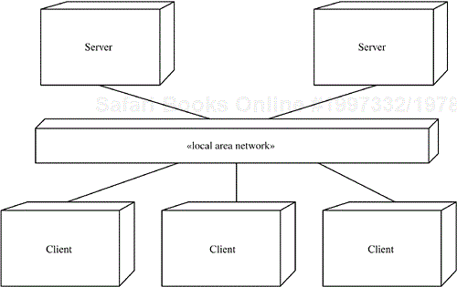
Middleware is a layer of software that sits above the heterogeneous operating system to provide a uniform platform above which distributed applications, such as client/server systems (Figure 2.14), can run (Bacon 1997). An early form of middleware was the remote procedure call (RPC). Other examples of middleware technology are DCE (Distributed Computing Environment) that uses RPC technology, Java remote method invocation (RMI), Component Object Model (COM) (Box 1998), Jini (Arnold et al. 1999), J2EE (Java 2 Platform Enterprise Edition) (Szyperski 2003), and CORBA (Common Object Request Broker Architecture) (Mowbray and Ruh 1997).
By providing a uniform way of interconnecting and reusing objects, middleware technologies such as CORBA, COM, and JavaBeans promote component reuse, and hence are also referred to as component technologies (Szyperski 2003). Distributed component technologies include CORBA, which is an OMG standard, COM and .NET from Microsoft, and JavaBeans and Jini connection technology from Sun Microsystems.
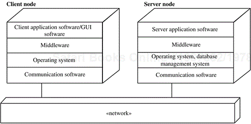
An example of middleware in a client/server configuration is shown in Figure 2.15. On the client node is the client application, which uses a graphical user interface (GUI). There is a standard operating system, such as Windows XP, and network communication software, such as TCP/IP (Transmission Control Protocol/Internet Protocol), which is the most widely used protocol on the Internet. A middleware layer sits above the operating system and the network communication software. On the server node is the server application software, which makes use of the middleware services that reside on top of the operating system (e.g., UNIX or Windows XP), and the network communication software. A file or database management system, usually relational, is used for long-term information storage.
Application components need to have a communication protocol for intercomponent communication—for example, between clients and servers. Distributed components communicate over a network using a network protocol, such as TCP/IP. Applications communicate using an application layer protocol that sits above TCP/IP, such as FTP (File Transfer Protocol), electronic mail, and HTTP (HyperText Transfer Protocol) on the World Wide Web.
XML (Extensible Markup Language) is a technology that allows different systems to interoperate through exchange of data and text. The Simple Object Access Protocol (SOAP) is a lightweight protocol, developed by the World Wide Web Consortium (W3C), that builds on XML and HTTP to permit exchange of information in a distributed environment. SOAP defines a unified approach for sending XML-encoded data consisting of three parts: an envelope that defines a framework for describing what is in a message and how to process it, a set of encoding rules for expressing instances of application-defined data types, and a convention for representing remote procedure calls and responses.
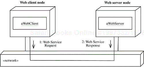
Applications provide services for clients. One example of application services is Web services, which use the World Wide Web for application-to-application communication. From a software perspective, Web services are the application programming interfaces (APIs) made available to provide a standard means of communication among different software applications on the World Wide Web. From a business application perspective, a Web service is business functionality provided by a company in the form of an explicit service over the Internet for other companies or programs to use. A Web service is provided by a service provider and may be composed of other services to form new services and applications. An example of a Web client invoking a Web service is given in Figure 2.16.
Several component technologies exist to support the building of applications by means of component technology and Web services, including .NET, J2EE, WebSphere, and WebLogic.
A registration service is provided for servers to make their services available to clients. Servers register their services with a registration service—a process referred to as publishing or registering the service. Most brokers, such as CORBA and Web service brokers, provide a registration service. For Web services, a service registry is provided to allow services to be published and located via the World Wide Web. Service providers register their services together with service descriptions in a service registry. Clients searching for a service can look up the service registry to find a suitable service. The Web Services Description Language (WSDL) is an XML-based language used to describe what a service does, where it resides, and how to invoke it.
In a distributed environment, an object broker is an intermediary in interactions between clients and servers. Servers register the services that they provide with the broker. Clients can then request these services via the broker. The broker provides location transparency and platform transparency. Sophisticated object brokers provide white pages (naming services) and yellow pages (trader services) to help clients locate services more easily. Broker patterns are described in Chapter 10.
An example of brokering technology is the Common Object Request Broker Architecture (CORBA), which is an open systems standard, developed by the Object Management Group, that allows communication between objects on heterogeneous platforms (Mowbray and Ruh 1997). The Object Request Broker (ORB) middleware allows client/server relationships between distributed objects. Server objects provide services that can be invoked from client objects by means of the ORB. Using an ORB, a client object can invoke an operation on a server object without having to know where the object is located, what platform (hardware and operating system) it is running on, what communication protocol is required to reach it, or what programming language it is implemented in.
Another example of brokering technology is a Web services broker. Information about a Web service can be defined by the Universal Description, Discovery, and Integration (UDDI) framework for Web services integration. A UDDI specification consists of several related documents and an XML schema that defines a SOAP-based protocol for registering and discovering Web services. A Web services broker can use the UDDI framework to provide a mechanism for clients to dynamically find services on the Web.
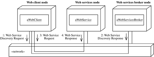
Figure 2.17 shows an example of a Web client making a Web services discovery request to a Web services broker and getting a response from the broker identifying a particular Web service. The Web client then sends a request to the Web server for the discovered service.
Although many legacy applications cannot be easily integrated into a software product line, one approach is to develop wrapper components. A wrapper component is a distributed application component that handles the communication and management of client requests to legacy applications (Mowbray and Ruh 1997). A wrapper registers its service with the naming service so that it can receive client service requests.
Most legacy applications were developed as stand-alone applications. In some cases the legacy code is modified so that the wrapper component can access it. However, such modification is often impractical because there is often little or no documentation and the original developers are no longer present. Consequently, wrapper components often interface to legacy code through crude mechanisms such as files, which might be purely sequential or indexed sequential files. The wrapper component reads or updates files maintained by the legacy application. If the legacy application uses a database, the database could be accessed directly through the use of database wrapper components that would hide the details of how to access the database. For example, with a relational database, the database wrapper would use Structured Query Language (SQL) statements to access the database.
Developers can integrate legacy code into a component-based application by placing a wrapper around the legacy code and providing an interface to it. The wrapper maps external requests from components into calls in the legacy code. The wrapper also maps outputs from the legacy code into responses to the component.
This chapter described key concepts in the design of software product lines, as well as important concepts for developing the component-based architecture of these systems. The object-oriented concepts introduced here form the basis of several of the forthcoming chapters. Chapter 6 will describe how static modeling is applied to modeling software product lines. Chapters 7 and 8 will describe how dynamic modeling is applied to modeling software product lines—Chapter 7 focusing on dynamic modeling between objects using object interaction modeling, and Chapter 8 focusing on dynamic modeling within an object using finite state machines.
This chapter also described the concepts of components and component-based systems, emphasizing component fundamentals rather than technologies, which tend to change frequently. The development of component-based software architectures will be described further in Chapter 11. All three case studies in Chapters 13, 14, and 15 will develop component-based software solutions.
[1] See Appendix A for an overview of the UML notation. To improve readibility, spaces are inserted in multiword names of classes, objects, and other design elements when they appear in the text itself. See Section A.11 in Appendix A for a complete explanation of the naming conventions used in this book.