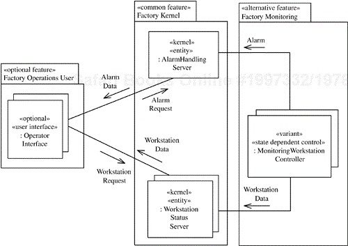
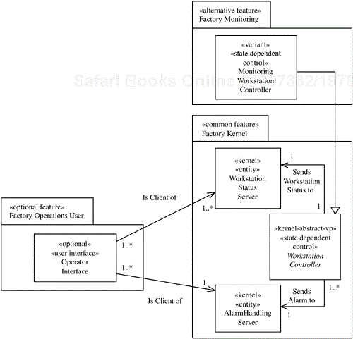
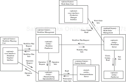
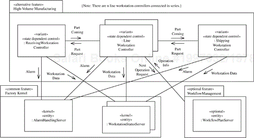
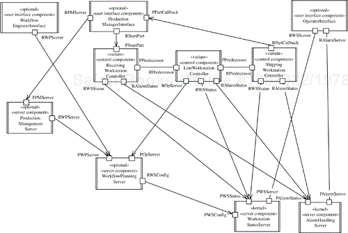
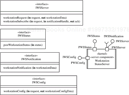
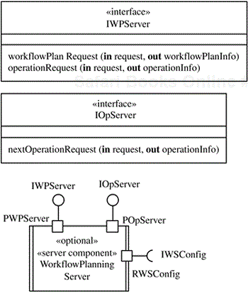
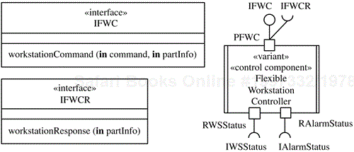
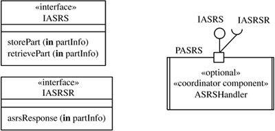
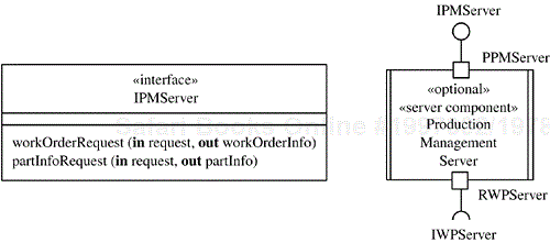
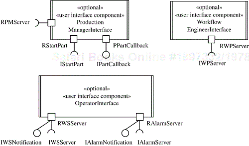
As another example of designing a software product line, this chapter describes a factory automation software product line. This is a highly distributed product line, with several clients and servers, a real-time control component, and examples of client/server communication, as well as peer-to-peer communication. Because this product line begins with existing factory automation systems that are candidates for modernization and inclusion in the product line, the reverse evolutionary engineering strategy is applied. This case study starts by analyzing the systems that are being considered for inclusion in the product line—namely, the factory monitoring, high-volume manufacturing, and flexible manufacturing systems. It then goes on to develop requirements, analysis, and design models for the integrated factory automation software product line.
The problem description is given in Section 15.1. Section 15.2 describes the use case model for the factory automation product line, which starts by modeling the use cases for factory monitoring, high-volume manufacturing, and flexible manufacturing systems in preparation for integration of the three use case models into a product line use case model. Section 15.3 goes on to describe the factory automation product line feature model, in which common, optional, and alternative features are determined from the use case model. Section 15.4 describes the product line static model, covering static modeling of both the product line context and entity classes. In both cases, static models for the factory monitoring, high-volume manufacturing, and flexible manufacturing systems are developed and then integrated into a product line static model. Section 15.5 describes dynamic modeling, starting with the kernel first approach in which communication diagrams are developed for each of the kernel use cases. Following this discussion, in Section 15.6 the product line evolution approach is used for dynamic modeling of the optional and alternative use cases. Section 15.7 describes the feature/class dependencies, explaining how they are determined from the dynamic model. Section 15.8 describes the design model for the factory automation software product line, which is designed as a layered architecture based on the Layers of Abstraction pattern combined with the client/server and control patterns. The design also takes an iterative approach in which the kernel software architecture is developed first, and then the optional and variant components are modeled. Section 15.9 describes software application engineering.
A factory automation system consists of several manufacturing workstations. The capabilities of factory automation systems vary widely. The factory automation product line encompasses high-volume manufacturing systems (which have high-volume production but low flexibility), flexible manufacturing systems (which have low-volume production but high flexibility), and factory monitoring systems.
Factory monitoring systems are relatively simple because part manufacturing is not carried out in these systems; instead, the status of the factory is monitored with a variety of sensors. These sensors are attached to factory robots, which send status information about the factory workstations to which they belong. In addition, they send factory alarms concerning undesirable situations in the factory that require human intervention. Factory operators view the status of the different workstations and view and update alarm conditions.
In high-volume manufacturing plants, manufacturing workstations are physically laid out in a manufacturing line such as an assembly line (for an example, see Figure 15.1). Parts are moved between workstations on a conveyor belt. A part is processed at each workstation in sequence. Because workstations are programmable, variations on a given product can be handled. Typically, multiple parts of the same type are produced, followed by multiple parts of a different type.
Each manufacturing workstation has a manufacturing robot for operating on the product and a pick-and-place robot for picking parts off and placing parts on the conveyor. Each robot is equipped with sensors and actuators. Sensors are used for monitoring operating conditions (e.g., detecting part arrival), and actuators are used for switching automation equipment on and off (e.g., switching the conveyor on and off). The first workstation is the receiving workstation, and the last workstation is the shipping workstation. These workstations have only a pick-and-place robot. All other workstations are referred to as line workstations; they have a manufacturing robot in addition to the pick-and-place robot. Factory operators look at workstation status and alarms.
The manufacturing steps required to manufacture a given part in the factory, from raw material to finished product, are defined in a workflow plan. The workflow plan defines the part type and the sequence of manufacturing operations. Each operation is carried out at a workstation. Workflow engineers create workflow plans and their constituent operations.
The processing of new parts in the factory is initiated when a human production manager creates a work order. The work order defines the quantity of parts required for a given part type.
In flexible manufacturing plants, a given part can be processed at any one of several manufacturing workstations of the same type. A part is dynamically allocated to a free workstation. Parts are moved between workstations on automated guided vehicles. Raw material, parts that have been partially processed, and finished parts are stored in an automated storage and retrieval system.
A flexible manufacturing system is a computer-controlled system for the automated manufacturing of parts in a factory. The flexible manufacturing system interfaces to robot controllers (abbreviated RC in Figure 15.2), an automated storage and retrieval system (ASRS), and an automated guided vehicle (AGV). In addition, it interacts with several human users—namely, production supervisors, human operators, and workflow engineers.
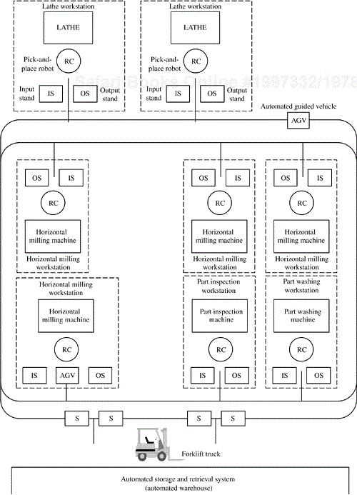
An example of the layout of the factory floor for a flexible manufacturing system is shown in Figure 15.2. There are several manufacturing workstations, most of which have the following components:
A microcomputer-controlled factory manufacturing robot, which could be a numerically controlled machine tool or assembly robot.
Two pickup/dropoff stands. One stand is used as an input stand (abbreviated IS in the figure), upon which an AGV can place a part. The second stand is used as an output stand (abbreviated OS), from which an AGV can remove a part.
A microcomputer-controlled pick-and-place robot for picking up a part from the input stand and placing it in the work location before the start of a manufacturing or assembly operation. The robot also picks up the part after the operation has been completed and places it on the output stand.
An automated storage and retrieval system is similar to an automated warehouse and is used to store raw material, parts between operations (work in process), and finished parts (i.e., ready to be shipped). For storage, an automated forklift truck takes a part from a pickup/dropoff stand (labeled S on Figure 15.2) and stores it in a location in the ASRS. For retrieval, the truck removes the part from the ASRS and puts it on the stand. The ASRS has several stands, each of which may function as an input (IS) or output (OS) stand.
Parts are moved between workstations and to/from the ASRS via automated guided vehicles. An AGV picks up a part from a pickup/dropoff stand at the source workstation or ASRS, and delivers it to a stand at the destination workstation or at the ASRS.
The manufacturing steps required to manufacture a given part in the factory, from raw material to finished product, are defined in a workflow plan. The workflow plan defines the part type and the sequence of manufacturing operations. Each operation is carried out at a manufacturing workstation. The workflow plan is defined by a human workflow engineer.
The processing of new parts in the factory is initiated when a human production supervisor creates a work order. The work order defines the quantity of parts required for a given part type.
This section describes the use case model for the factory automation software product line. With the reverse engineering approach, use cases are developed first for each of the major factory systems: factory monitoring systems, high-volume manufacturing systems, and flexible manufacturing systems. As the use cases are developed, it is useful to look for use cases that can be reused among these systems—in particular, to attempt to identify product line commonality, which can be described in kernel use cases.
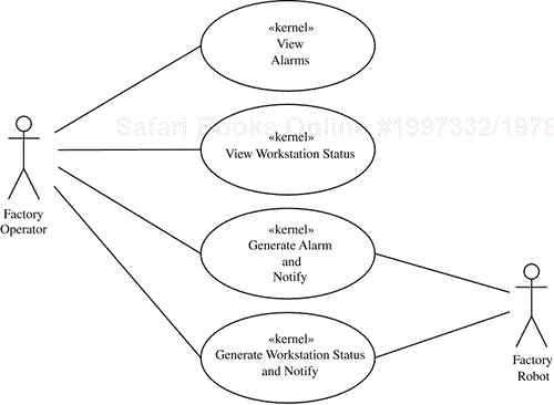
Factory monitoring systems are the simplest of the three major kinds of factory systems. They have one human actor: Factory Operator. Four use cases involve Factory Operator, as either primary or secondary actor, as depicted in Figure 15.3 and described here:
View Alarms. The factory operator views outstanding alarms and acknowledges that the cause of an alarm is being addressed. The operator may also subscribe to receive notification of alarms of a given type.View Workstation Status. The factory operator requests to view the current status of one or more factory workstations. Operator requests are made on demand. The operator may also subscribe to receive notification of changes in workstation status.Generate Workstation Status and Notify. Workstation status is generated on an ongoing basis, for example, when processing of a part at a workstation starts or completes. Operators are notified of workstation status events to which they have subscribed. There is one variation point within the use case—Workstation Type—which can be a factory monitoring workstation, a high-volume manufacturing workstation, or a flexible manufacturing workstation.Generate Alarm and Notify. If an alarm condition is detected during part processing, an alarm is generated. Operators are notified of alarms to which they have subscribed. There is one variation point within the use case—Workstation Type—which can be a factory monitoring workstation, a high-volume manufacturing workstation, or a flexible manufacturing workstation.
Next, the use cases for high-volume manufacturing systems are developed. The human actors are Production Manager, Factory Operator, and WorkflowEngineer. In addition, there are actors that correspond to external systems. These are the Manufacturing Robot and Pick & Place Robot actors. The use cases are described next and illustrated in Figures 15.3 through 15.5.
Factory Operator initiates or participates in four use cases, as described for factory monitoring systems in the previous section (see Figure 15.3). These use cases—View Alarms, View Workstation Status, Generate Alarm and Notify, and Generate Workstation Status and Notify—are also used in high-volume manufacturing systems.
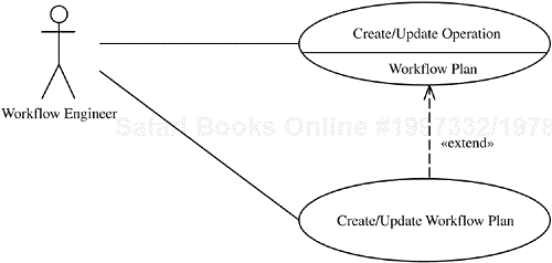
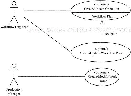
Workflow Engineer defines several manufacturing operations and then creates a workflow plan to define a sequence of operations to manufacture a part. Two related use cases are developed for this purpose (see Figure 15.4). The workflow engineer uses the Create/Update Operation use case to create, update, and modify manufacturing operations. Create/Update Operation is a base use case that is executed once for each operation created. Workflow Engineer can then use the Create/Update Workflow Plan use case to create, update, and modify a workflow plan that defines the sequence of operations to manufacture a part. The Create/Update Workflow Plan use case extends the Create/Update Operation use case. Thus an optional alternative in the Create/Update Operation use case is to create a workflow plan.
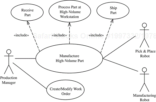
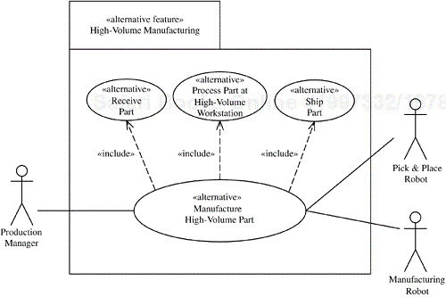
Production Manager initiates the Create/Modify Work Order use case to create and modify work orders. Production Manager also initiates a complex use case called Manufacture High-Volume Part, which deals with processing parts in a high-volume factory (see Figure 15.5). The production manager releases a work order to be processed in the factory. Each part starts processing at the receiving workstation, where a raw part is loaded onto the conveyor belt. At the next workstation the part is picked off the conveyor belt by the pick-and-place robot, has a manufacturing operation performed on it by the manufacturing robot, and is then placed back on the conveyor belt by the pick-and-place robot and transported to the next workstation. This process continues until the finished part reaches the shipping workstation where it is picked off the conveyor in preparation for shipping to the customer. A just-in-time algorithm is used in the factory, meaning that a workstation receives a part only when it is ready to process a part, so parts do not pile up at each workstation.
From examination of the Manufacture High-Volume Part use case, it can be determined that the use case is made more general by being divided into the following three abstract use cases, which are included in the Manufacture High-Volume Part concrete use case:
Receive Part. The receiving workstation receives the request from the production manager to manufacture a new part and sends the part to the first line manufacturing workstation in the sequence.Process Part at High-Volume Workstation. The line manufacturing workstation receives the part from the previous workstation (referred to as the predecessor workstation), performs the manufacturing operation on the part, and sends the part to the next line manufacturing workstation in the sequence (referred to as the successor workstation). This use case is repeated several times.Ship Part. The last line manufacturing workstation sends the finished part to the shipping workstation, which sends an acknowledgment of part completion to the production manager.
Flexible manufacturing systems have several use cases in common with factory monitoring and high-volume manufacturing systems. They support the same four Factory Operator use cases described in Section 15.2.1 and illustrated in Figure 15.3. And like high-volume systems, flexible manufacturing systems need three additional use cases: Create/Update Operation and Create/Update Workflow Plan (for workflow planning), and Create/Modify Work Order, as described in Section 15.2.2. However, flexible manufacturing systems handle part processing quite differently from high-volume systems.
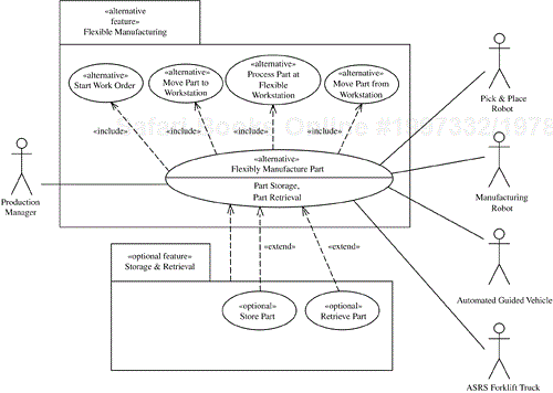
The Flexibly Manufacture Part use case addresses part processing in a flexible manufacturing system (see Figure 15.6). The raw material to make the part is initially stored in the ASRS. The part is then retrieved by an ASRS forklift truck and moved to the ASRS stand. Next, an AGV is sent to pick up the part and move it to the input stand of the first workstation. After delivery, the part is processed at the workstation and then placed on the workstation output stand. From there the part is picked up by an AGV and either moved to the next workstation or moved back to the ASRS for temporary storage. A finished part is moved back to the ASRS and then shipped.
It is possible to have a more limited flexible manufacturing system that uses the ASRS only for storing raw material prior to the start of part manufacturing and for storing finished parts after the completion of part manufacturing. This more limited form of part manufacturing is addressed by the Flexibly Manufacture Part use case. The more general use case, in which the ASRS is used for intermediate storage and retrieval during part manufacturing, consists of two extension use cases to the Flexibly Manufacture Part use case—Store Part and Retrieve Part—as shown in Figure 15.6.
The concrete Flexibly Manufacture Part use case can be divided into four abstract inclusion use cases as follows:
Start Work Order. The factory supervisor releases a work order to the factory floor. The first workstation for each part is determined from the workflow plan.Move Part to Workstation. A workstation is allocated to a part. The part is moved from the ASRS to the workstation input stand.Move Part from Workstation. The next workstation is determined for the part. If a workstation is available, an AGV moves the part to the next workstation's input stand. If a workstation is unavailable, the AGV moves the part to the ASRS.Process Part at Flexible Workstation. The pick-and-place robot picks up the part from the workstation input stand and places it in the workplace (e.g., location, bench). The manufacturing robot operates on the part. When the operation is complete, the pick-and-place robot picks up the part and places it on the workstation output stand.
The Store Part extension use case extends Flexibly Manufacture Part at the extension point Part Storage, and the Retrieve Part extension use case extends Flexibly Manufacture Part at the extension point Part Retrieval, as shown in Figure 15.6.
As described in Section 4.8.2, there is a product line condition that must be true for the extension use case to be enabled. A product line member that provides the ASRS extensions for intermediate storage has the product line condition called [storage] set to true. In addition, for the extension use case to be executed, the selection condition must also be true during runtime execution. To invoke the Store Part extension use case at the extension point Part Storage, both the product line condition and the selection condition [store command] must be true; thus, [storage AND store command] must be true (see Figure 15.6). For the Retrieve Part extension use case to be invoked at the extension point Part Retrieval, both the product line condition and the selection condition [retrieve command] must be true; thus, [storage AND retrieve command] must be true.
Commonality/variability analysis of the factory automation software product line begins with analysis of the three use case models described in Section 15.2 in search of use cases that are common across the product line—that is, use cases that all members of the product line use. These common use cases are referred to as kernel use cases; they form the basis for determining the common features of the product line. After the kernel use cases have been determined, groups of use cases that are common to a subset of the members of the family are sought; these use cases form optional use cases or optional features.
Analysis of the factory automation software product line reveals that the following factory operator use cases are used by all factory automation systems, so they are categorized as kernel use cases (Figure 15.7): View Alarms, View Workstation Status, Generate Alarm and Notify, and Generate Workstation Status and Notify. Two of these use cases—View Alarms and View Workstation Status—are used directly by all factory systems. The other two use cases—Generate Alarm and Notify and Generate Workstation Status and Notify—are also used by all factory systems, but with one difference. The difference is that the workstations that generate the alarms and workstation status are different, although the way they behave in these use cases is identical. The nature of the alarms and workstation status varies in different factories. It is therefore necessary to provide the capability for different alarms and workstation status to be configured so that these two use cases can be reused. Because of this variability, a variation point called Workstation Type needs to be introduced into each use case. The value of Workstation Type needs to be set during product line member derivation and remain unchanged for a given product line member.
These four use cases have the potential of being combined into one common feature. However, a factory could be totally automated, lacking any operator user interface, although still needing to store and retrieve workstation and alarm status, which could then be accessed remotely from a different system. To achieve this overall functionality, the preceding four use cases are mapped to two features: a common feature called Factory Kernel (which consists of the functionality of the four kernel use cases without the user interface) and an optional feature called Factory Operations User (which consists of the user interface functionality). With the feature notation described in Chapter 5, these features are depicted as follows:
«common feature» Factory Kernel
«optional feature» Factory Operations User {prerequisite = Factory
Kernel}
The Create/Update Operation, Create/Update Workflow Plan, and Create/Modify Work Order use cases are used by a subset of the family—namely, both high-volume and flexible manufacturing systems, but not factory monitoring systems. Hence they are categorized as optional use cases, as Figure 15.8 shows.
There are two approaches for handling workflow plans and operations because there must be some way of entering workflow plans into the system. It is possible for both to be present in any one system. For this reason, the Create/Update Operation and Create/Update Workflow Plan use cases are mapped to two features:
Workflow Management. Storing and updating workflow plans, either created locally by a workflow engineer or downloaded from an external system, imply the need for server functionality to manage, store, and update requests from different types of clients. TheWorkflow Managementfeature provides all the functionality of the use cases apart from the user interface:«optional feature» Workflow Management {prerequisite = Factory Kernel}Workflow Planning User. Creation and modification of workflow plans imply the need for the client user interface to allow a workflow engineer to create and modify operations and workflow plans. TheWorkflow Planning Userfeature depends on theWorkflow Managementfeature:
«optional feature» Workflow Planning User {prerequisite = Workflow
Management}
Work orders also could be downloaded from an external system. Consequently, the Create/Modify Work Order use case needs to be mapped to two optional features called Work Order User and Work Order Management, respectively—the former providing the user interface and the latter providing all the other functionality of the use case. The Work Order User feature depends on the Work Order Management feature:
«optional feature» Work Order Management {mutually includes = Workflow
Management}

«optional feature» Work Order User {prerequisite = Work Order
Management}
The Manufacture High-Volume Part use cases are specific to high-volume manufacturing systems. Consequently, the three abstract use cases and the one concrete use case are categorized as alternative use cases. Furthermore, they are considered as one alternative feature and depicted as one use case package called the High-Volume Manufacturing feature (see Figure 15.9):
«alternative feature» High-Volume Manufacturing {mutually includes =
Work Order Management}
Because the Flexibly Manufacture Part use cases (see Section 15.2.3) are specific to flexible manufacturing systems, they are also categorized as alternative use cases and treated as one use case package representing an alternative feature. Within flexible manufacturing systems, there is a choice of whether or not to have parts stored in and retrieved from an automated storage and retrieval system during part processing. Hence the features are Flexible Manufacturing (encompassing the Flexibly Manufacture Part use case and its four abstract use cases) and Storage and Retrieval (see Figure 15.10), which consists of the Retrieve Part and Store Part extension use cases:
«alternative feature» Flexible Manufacturing {mutually includes = Work
Order Management}

«optional feature» Storage and Retrieval {prerequisite = Flexible
Manufacturing}
In addition, an alternative Factory Monitoring feature captures the variability required by factory monitoring systems. This feature corresponds not to a use case but rather to a variation point called Workstation Type in the two use cases that deal with workstation status: View Workstation Status and Generate Workstation Status and Notify:
«alternative feature» Factory Monitoring {prerequisite = Factory
Kernel}
The feature/use case dependencies of the entire factory automation software product line are depicted in Table 15.1, which shows the features, feature categories, use cases that each feature depends on, and use case categories. Also depicted is a variation point that affects three features.
Table 15.1. Feature/use case dependencies of the factory automation software product line
Once the features have been determined, they are organized into a feature dependency diagram (see Figure 15.11), which uses the static modeling notation. Each feature and feature group is depicted as a metaclass with the stereotype identifying the feature category or feature group category. The feature dependency diagram depicts the common feature as the root node. Apart from the common feature, all features are optional or alternative features. There is also one feature constraint in the form an exactly-one-of feature group: the Factory Management feature group, so called because a factory system must be one of the three alternatives—monitoring, high-volume manufacturing, or flexible manufacturing:
«exactly-one-of feature group» Factory Management {alternative =
Factory Monitoring, High-Volume Manufacturing, Flexible
Manufacturing}
Two optional features in Figure 15.11 (Workflow Management and Factory Operations User) and the Factory Management feature group depend directly on the Factory Kernel feature. Two alternative features (High-Volume Manufacturing and Flexible Manufacturing) depend mutually inclusively on the Work Order Management optional feature, which in turn depends mutually inclusively on the Workflow Management feature. The mutually includes dependency is used instead of the requires dependency so that the Workflow Management and Work Order Management optional features are prevented from being selected independently. They must be selected in conjunction with one of the alternative features (High-Volume Manufacturing or Flexible Manufacturing) to create a viable factory automation system. The remaining optional features—Workflow Planning User, Work Order User, and Storage & Retrieval—can be selected for a product line member if their prerequisite features are also selected.
In addition to the functional features that have been mentioned already, several configuration parameters need to be defined when a factory member system is deployed. These parameters include the following:
Number of workstations, workstation IDs
Number of operators, operator names, and operator IDs
Workstation status ID and status text
Alarm ID, alarm type, and alarm text
At each workstation: IDs of robots and sensors
The static model for the factory automation product line is developed with the reverse engineering strategy, whereby static models are developed first for the different kinds of factory automation systems—namely, factory monitoring systems, high-volume manufacturing systems, and flexible manufacturing systems. These three static models are then integrated into a static model for the entire factory automation product line.
The static model for factory monitoring systems is quite simple, as shown in Figure 15.12. A factory consists of factory monitoring workstations, which generate alarms. Thus the Factory class is an aggregate class composed of the Factory Monitoring Workstation class.
Because a workstation can generate multiple alarms, there is a one-to-many relationship between the Factory Monitoring Workstation class and the Alarm class. Each Factory Monitoring Workstation also generates Workstation Status (a one-to-one association), which is viewed by the Factory Operator. Any operator can view the status of any workstation, which implies a many-to-many association.
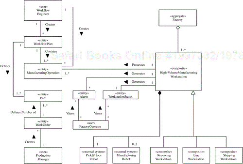
The static model for the high-volume manufacturing system is shown in Figure 15.13. Because a factory consists of workstations, Factory is modeled as an aggregate class composed of High-Volume Manufacturing Workstation classes. There are three types of high-volume manufacturing workstations—receiving workstations, line workstations, and shipping workstations—so they are modeled as a generalization/specialization hierarchy; that is, the High-Volume Manufacturing Workstation class is specialized into three subclasses: Receiving Workstation, Shipping Workstation, and Line Workstation.
A workflow plan defines the steps for manufacturing a part of a given type; it contains several operations, where an operation defines a single manufacturing step carried out at a workstation. Consequently, there is a one-to-many association between the Workflow Plan class and the Manufacturing Operation class. Because several different operations are processed at a given factory workstation, there is also a one-to-many association between the High-Volume Manufacturing Workstation class and the Manufacturing Operation class. A work order defines the number of parts to be manufactured of a given part type. Thus the Work Order class has a one-to-many association with the Part class. Because a workflow plan defines how all parts of a given part type are manufactured, the Workflow Plan class also has a one-to-many association with the Part class.
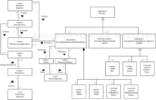
The static model for flexible manufacturing systems is more complicated, as shown in Figure 15.14. The factory is an aggregation of factory workstations, automated guided vehicles (AGVs), and an automated storage and retrieval system (ASRS). An ASRS consists of ASRS bins (where parts are stored), ASRS stands (where parts are placed after retrieval from an ASRS bin or prior to storage in an ASRS bin), and forklift trucks (which move parts from the stands to the bins for storage and vice versa for retrieval). The static model consists of an aggregate Factory class, which is composed of the Flexible Manufacturing Workstation class, the Automated Guided Vehicle class, and the Automated Storage & Retrieval System (ASRS) class. The ASRS class is also an aggregate class, composed of the ASRS Bin, ASRS Stand, and Forklift Truck classes. The Workflow Plan, Manufacturing Operation, Work Order, and Part classes are modeled in the same way as in the static model for the high-volume manufacturing system (see Figure 15.13).
The way to develop the static model for the factory automation product line is to integrate the static models for the three different kinds of factory systems: factory monitoring systems, high-volume manufacturing systems, and flexible manufacturing systems. This kind of model integration is similar to view integration in logical database design, and for this reason the three different models are referred to as views in the following discussion. The integrated static model for the factory automation software product line is described in this section.
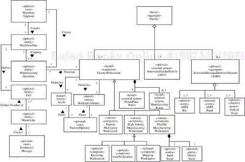
When the factory monitoring, high-volume manufacturing, and flexible manufacturing static models are integrated (see Figure 15.15), classes that are common to all three views become kernel classes. Classes that are in one view but not the others become optional classes. Classes that are different in each view are generalized so that the different classes become specialized subclasses of the superclass.
Some classes exist in one kind of system but not the others; for example, the AGV and ASRS classes exist only in flexible manufacturing systems. Some classes exist in more than one kind of system; for example, Workflow Plan and Manufacturing Operation exist in both flexible and high-volume manufacturing systems.
Classes that vary from one kind of system to another, such as Factory Workstation, are designed as subclasses of a generalized superclass. Thus a Factory Workstation superclass is introduced (which does not exist in any of the three views shown in Figures 15.12 through 15.14) and specialized to produce three subclass variants: Factory Monitoring Workstation, High-Volume Manufacturing Workstation, and Flexible Manufacturing Workstation. As in the static model for the high-volume manufacturing system, High-Volume Manufacturing Workstation is specialized into three subclasses: Receiving Workstation, Line Workstation, and Shipping Workstation.
Factory is an aggregate class composed of the Factory Workstation class, the optional Automated Guided Vehicle (AGV) class, and the optional Automated Storage and Retrieval System (ASRS) class. The first of these is used by all factory systems, albeit specialized as required. The latter two classes are used only in flexible manufacturing systems. As in the static model for the flexible manufacturing system, the ASRS class is an aggregate class composed of the ASRS Bin, ASRS Stand, and Forklift Truck classes.
The attributes of the classes in the static model are depicted in Figure 15.16. It is necessary to determine the attributes of the entity classes in particular before developing the communication diagrams because several of the objects in communication diagrams read or update the values of the entity class attributes.
The product line context class diagram, which defines the boundary of a product line system, is determined in the reverse engineering approach by consideration of the context class diagrams of each of the major factory systems. For a factory monitoring system, the external classes consist of one external user (Factory Operator) and two external systems (Manufacturing Robot and Pick & Place Robot), as shown in Figure 15.17.
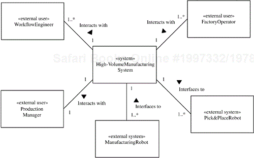
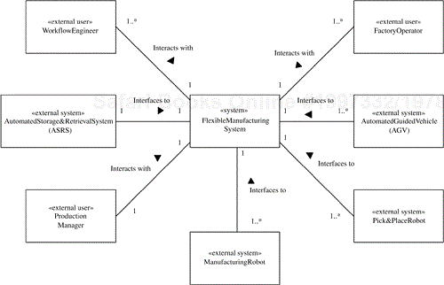
For a high-volume manufacturing system (see Figure 15.18), the external classes consist of three external users (Production Manager, Workflow Engineer, and Factory Operator) and the same two external systems (Manufacturing Robot and Pick & Place Robot). A flexible manufacturing system has the same five external classes, as illustrated in Figure 15.19. In addition, there are two further external systems: Automated Guided Vehicle (AGV) and Automated Storage and Retrieval System (ASRS).
The context class diagrams for each system are integrated to create the product line context class diagram, as shown in Figure 15.20. In this diagram the external classes that are required by all factory systems are kernel. Two of the external systems (Manufacturing Robot and Pick & Place Robot) and one external user (Factory Operator) fall into this category. However, because of an additional product line requirement that some factory systems should operate unmanned, the Factory Operator external user class is recategorized as optional. The remaining external classes are optional because they are needed in only some of factory automation systems, and individual members of the product line can be configured without them. The optional classes are the external systems AGV and ASRS (which are needed only in flexible manufacturing systems) and the two external users Production Manager and Workflow Engineer (which are needed by high-volume manufacturing systems and flexible manufacturing systems but not by factory monitoring systems).
In order to understand fully the relationship between the use cases, it is necessary to analyze how the objects in the factory automation product line participate in the use cases. The dynamic model for the product line is depicted on communication diagrams. Statecharts are also used for the dynamic modeling of state-dependent objects, as described in Chapter 8. Dynamic modeling is carried out first for the kernel of the product line, starting with the kernel use cases, and then (using product line evolution) for the optional and alternative use cases. Because object/class structuring and dynamic modeling are iterative activities, they are both described in this section.
During dynamic modeling, the objects that participate in each use case are determined, and then the sequence of interactions among the objects is analyzed. The first step is to analyze how the factory automation product line is structured into objects.
Entity objects are long-living objects that store information. The entity objects for the factory automation product line are Workflow Plan, Manufacturing Operation, Work Order, and Part. There are also Workstation Status and Alarm entity objects. The entity objects are depicted in the static model in Figure 15.15, and their attributes are given in Figure 15.16. The entity objects are all server objects that are accessed by various client objects. Hence, on communication diagrams the entity objects are depicted as server objects: Workflow Plan Server, Manufacturing Operation Server, Work Order Server, Part Server, Workstation Status Server, and Alarm Server.
For each of the human actors there needs to be a user interface object. These objects are Workflow Engineer Interface, Production Manager Interface, and Factory Operator Interface.
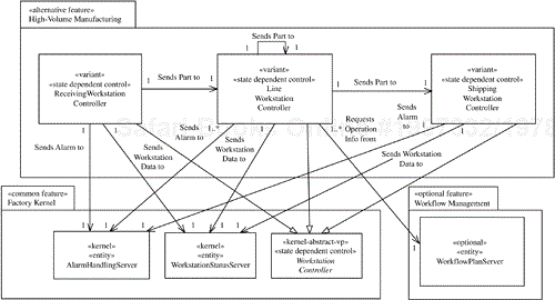
For the factory automation product line, which is distributed in nature, several control objects provide distributed control. Several instances of the Workstation Controller class exist—one instance for each manufacturing workstation. However, different variants of this class are used by the different members of the product line. For high-volume systems, there is one instance of Receiving Workstation Controller, one of Shipping Workstation Controller, and several of Line Workstation Controller (one for each workstation). For flexible systems, there is one instance of Flexible Workstation Controller for each workstation. For factory monitoring systems, there is one instance of Monitoring Workstation Controller for each workstation.
After object structuring, dynamic modeling for product lines follows the kernel first approach as described in this section. First the communication diagrams for the kernel use cases—namely, the factory monitoring use cases—are determined. In analyzing the object communication for each use case, various architectural patterns are recognized for future reference during design,
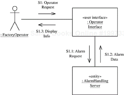
Consider the Factory Operator use cases, which form the basis of the factory monitoring communication diagrams. Two of these communication diagrams involve the Client/Server pattern, in which a client—in this case a user interface client—interacts with a server. First consider the communication diagram for the View Alarms use case, depicted in Figure 15.21. The message sequence is as follows:
S1: The factory operator requests an alarm handling service—for example, to view alarms or to subscribe to receive alarm messages of a specific type.
S1.1:
Operator Interfacesends the alarm request toAlarm Handling Server.S1.2:
Alarm Handling Serverperforms the request—for example, reads the list of current alarms or adds the name of this client to the subscription list—and sends a response to theOperator Interfaceobject.S1.3:
Operator Interfacedisplays the response—for example, alarm information—to the operator.
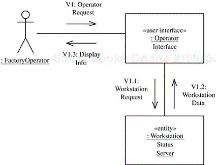
The communication diagram for the View Workstation Status use case also represents the Client/Server pattern and is very similar (Figure 15.22). The message sequence is as follows:
V1: The factory operator requests a workstation status service—for example, to view the current status of a workstation.
V1.1:
Operator Interfacesends a workstation status request toWorkstation Status Server.V1.2:
Workstation Status Serverresponds—for example, with the requested workstation status data.V1.3:
Operator Interfacedisplays the workstation status information to the operator.
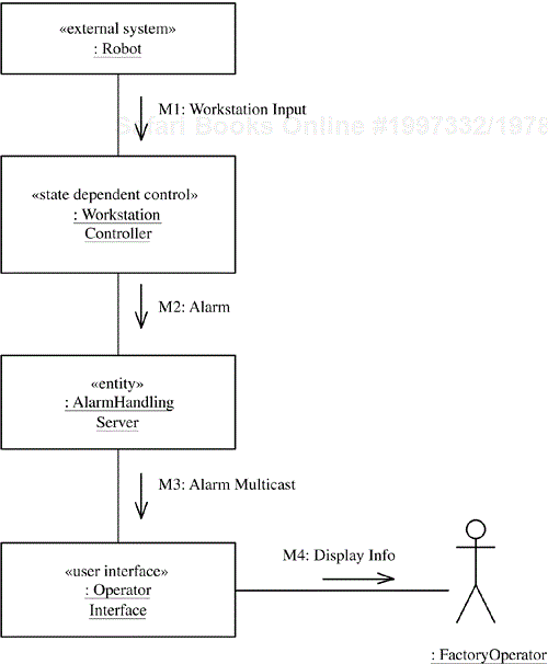
The two other kernel use cases are Subscription/Notification patterns, in which a client is notified of new events previously subscribed to in a client/server use case. Consider the communication diagram for the Generate Alarm and Notify use case, shown in Figure 15.23. The message sequence is as follows:
M1:
Workstation Controllerreceives workstation input from the external robot, indicating a problem condition.M2:
Workstation Controllersends an alarm toAlarm Handling Server.M3:
Alarm Handling Serversends a multicast message containing the alarm to all subscribers registered to receive messages of this type.M4:
Operator Interfacereceives the alarm notification and displays the information to the factory operator.
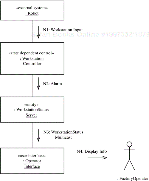
The communication diagram for the Generate Workstation Status and Notify use case is also a Subscription/Notification pattern and is shown in Figure 15.24. The message sequence is as follows:
N1:
Workstation Controllerreceives workstation input from the external robot, indicating a change in workstation status—for example, part completed.N2:
Workstation Controllersends a workstation status message toWorkstation Status Server.N3:
Workstation Status Serversends a multicast message containing the new workstation status to all subscribers registered to receive messages of this type.N4:
Operator Interfacereceives the workstation status message and displays the information to the factory operator.
After the kernel first approach is applied to development of the kernel communication diagrams, the product line evolution approach is used to develop the communication diagrams for the optional and alternative use cases. This approach is used for both the high-volume and the flexible manufacturing use cases.
With the product line evolution approach, the communication diagrams for the high-volume manufacturing use cases are determined next.
Consider first the interactions for the Factory Operator use cases. The first two communication diagrams—for View Alarms and View Workstation Status—are identical to the factory monitoring system diagrams for those use cases (see Figures 15.21 and 15.22). The other two communication diagrams—for Generate Alarm and Notify and Generate Workstation Status and Notify—are very similar to the factory monitoring system diagrams for those use cases (see Figures 15.23 and 15.24), with one subtle difference.
There are three different types of Workstation Controller objects: Monitoring Workstation Controller, (high-volume) Line Workstation Controller, and Flexible Workstation Controller. However, the way these three Workstation Controller variants operate in the Generate Alarm and Notify and Generate Workstation Status and Notify use cases is identical. Consequently, the generalized form of the Workstation Controller is used, rather than a specific subclass. (Workstation Controller is an abstract class that needs to be specialized as required for a given kind of factory before it can be instantiated.)
The workflow and work order use cases are those that involve workflow planning, as carried out by the workflow engineer, and work order management, as performed by the production manager.
Consider the workflow planning use cases initiated by Workflow Engineer. These use cases are used in both high-volume and flexible systems. A workflow engineer has to create manufacturing operations and then create a workflow plan that consists of a sequence of operations. Two use cases are used for this purpose (see Section 15.2.2 and Figure 15.8): Create/Update Operation and Create/Update Workflow Plan, where Create/Update Workflow Plan extends Create/Update Operation (see Figure 15.4). First consider the communication diagram for the Create/Update Operation use case (see Figure 15.25). The message sequence is as follows:
O1:
Workflow Engineerinputs information for creating an operation toWorkflow Engineer Interface. This information includes the operation name, workstation type, and robot programs to be used.O1.1:
Workflow Engineer Interfacesends aCreate Operationrequest toManufacturing Operation Server.O1.2:
Manufacturing Operation Serversends aCheck Workstationmessage toWorkstation Status Server, which maintains information about all the manufacturing workstations.O1.3:
Workstation Status Serverresponds with aWorkstation Statusmessage, allowingManufacturing Operation Serverto check whether the workstation type exists for the new operation.O1.4:
Manufacturing Operation Serversends the operation information toWorkflow Engineer Interface.O1.5:
Workflow Engineer Interfaceobject displays the operation information toWorkflow Engineer. The engineer may iterate, creating more operations.
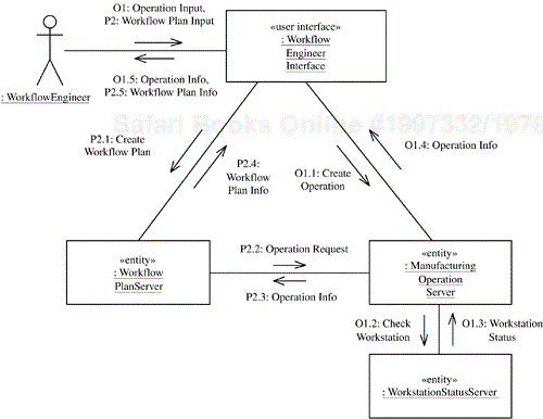
Figure 15.25. Communication diagram for the Create/Update Operation and Create/Update Workflow Plan use cases
Now consider the Create/Update Workflow Plan use case (also shown in Figure 15.8), which extends Create/Update Operation because it creates the workflow plan from operations created in the Create/Update Operation use case. The message sequence for the communication diagram shown in Figure 15.25 is as follows (the sequence numbering starts with 2 because the sequence follows on from operation creation):
P2:
Workflow Engineerinputs information for creating a workflow plan toWorkflow Engineer Interface. This information includes the plan name and part type, raw material, and operation information for the first manufacturing operation.P2.1:
Workflow Engineer Interfacesends aCreate Workflow Planrequest toWorkflow Plan Server.P2.2:
Workflow Plan Serversends anOperation Requestmessage toManufacturing Operation Server.P2.3:
Manufacturing Operation Serverresponds with information about the requested operation.P2.4:
Workflow Plan Serversends the workflow plan information toWorkflow Engineer Interface.P2.5:
Workflow Engineer Interfacedisplays the workflow plan information toWorkflow Engineer. The engineer adds other operations to the workflow plan.
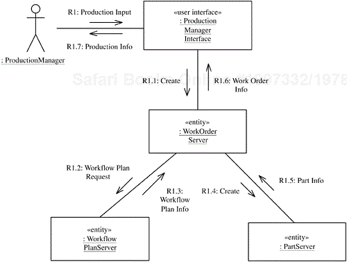
Next consider the communication diagram for the Create/Modify Work Order use case initiated by Production Manager, in which three entity objects—Work Order Server, Part Server, and Workflow Plan Server—are accessed (see Figure 15.26). The message sequence is as follows:
R1:
Production Managerinputs production information toProduction Manager Interface. This information includes the type of part to be manufactured.R1.1:
Production Manager Interfacesends aCreaterequest toWork Order Server.R1.2:
Work Order Serversends aWorkflow Plan Requestmessage toWorkflow Plan Server, which retrieves workflow plan information for the specified part type.R1.3:
Workflow Plan Serverreturns the workflow plan information toWork Order Server.R1.4:
Work Order Serversends aCreaterequest toPart Serverfor each part to be manufactured.R1.5:
Part Serveracknowledges part creation.R1.6:
Work Order Serversends the work order information toProduction Manager Interface.R1.7:
Production Manager Interfacedisplays the production information toProduction Manager.
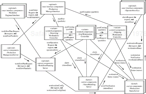
The high-volume manufacturing use case is a complex use case initiated by the production manager and called Manufacture High-Volume Part, in which a part is manufactured in the high-volume factory from raw material to finished product. This use case requires three different types of workstation controllers: a Receiving Workstation Controller object, several Line Workstation Controller objects, and a Shipping Workstation Controller object. There is one instance of the Line Workstation Controller class for each manufacturing workstation, and the instances are connected in series. When the production manager releases a work order to the factory, a Start Part message identifying the part ID and number of parts required is sent to Receiving Workstation Controller. This step ensures that for each part to be manufactured, a piece of raw material of the appropriate type is obtained and loaded onto the conveyor. At the shipping workstation, the Shipping Workstation Controller object removes finished parts from the conveyor and places them in a shipping area.
In a just-in-time algorithm, a workstation requests a part only when it is ready to process a part, so parts do not pile up at a workstation. When a workstation completes a part, it waits for a message from its successor workstation requesting the part. When the message is received, the workstation controller sends a Place command to the Pick & Place Robot to place the part on the conveyor. Next, the workstation controller sends a Part Coming message to the successor workstation and a Part Request message to the predecessor workstation. The Receiving Workstation Controller object maintains a count of the remaining number of parts for a given work order. Shipping Workstation Controller controls the removal of each finished part from the conveyor in preparation for shipping, after which it sends a Part Complete message to Production Manager Interface.
The three abstract use cases for part manufacturing (shown in Figure 15.9) are as follows:
Receive Part.Receiving Workstation Controllersends the part to the firstLine Workstation Controllerobject in the sequence.Process Part at High-Volume Workstation.Line Workstation Controllern sends part toLine Workstation Controllern + 1. This use case is repeated several times.Ship Part. The lastLine Workstation Controllerobject sends the part toShipping Workstation Controller.
A concrete use case for a part that has to visit n line workstations consists of one execution of the Receive Part use case (A), w – 1 (where w is the number of line workstation controllers) executions of the Process Part at High-Volume Workstation use case (B), and one execution of the Ship Part use case (C). The three part manufacturing abstract use cases are shown on communication diagrams (Figures 15.30 through 15.32), where events are labeled A, B, and C, corresponding to the three use cases described here.
In general, a workstation controller receives a part from a predecessor workstation controller (which could be a receiving or line workstation controller) and sends a part to a successor workstation controller (which could be a line or shipping workstation controller).
Because Workstation Controller is a state-dependent control object, it is defined by means of a statechart, which is described next, prior to the detailed description of the three communication diagrams.
The statechart for Line Workstation Controller consists of two orthogonal statecharts: the Part Processing statechart and the Part Requesting statechart. The two orthogonal statecharts are depicted as superstates on a high-level statechart, with a dashed line separating them (see Figure 15.27). At any one time, a workstation controller is in one of the substates of the High-Volume Part Processing superstate (see Figure 15.28), reflecting the current situation in processing of the part at this workstation; and in one of the substates of the Part Requesting superstate (see Figure 15.29), reflecting whether or not a part has been requested by the successor workstation. This orthogonal statechart does not imply that there is any concurrency within a Line Workstation Controller object, but merely that it is simpler to model these relatively independent event occurrences in this way.

Figure 15.28. Statechart for Line Workstation Controller: decomposition of the High-Volume Part Processing superstate

Figure 15.29. Statechart for Line Workstation Controller: decomposition of the Part Requesting superstate
The High-Volume Part Processing superstate contains the following substates. The transitions between the substates are described in the context of the communication diagrams (Figures 15.30–15.32):
Awaiting Part from Predecessor Workstation. This is the initial state, in which the workstation is idle, waiting for the arrival of a part.Part Arriving. This state is entered when the line workstation controller receives aPart Comingmessage from the predecessor workstation indicating that the next part is on the way.Robot Picking. The pick-and-place robot is picking the part off the conveyor belt and bringing it to the workstation. This state is entered when the part has arrived at the workstation.Operating on Part. The manufacturing robot is operating on the part. This state is entered when the line workstation controller receives a message indicating that the part is ready at the workstation.Robot Placing. The pick-and-place robot is placing the part on the conveyor belt to send to the successor workstation. This state is entered when robot manufacturing at this workstation has been completed and a part request has been received from the successor workstation.Awaiting Part Request from Successor Workstation. This state is entered when robot manufacturing at this workstation has been completed but a part request has not been received from the successor workstation.
The Part Requesting superstate has the following substates:
Part Not Requested. A part has not been requested by the successor workstation.Part Has Been Requested. A part has been requested by the successor workstation.
These two substates are used as conditions to be checked in the Part Processing statechart for determining what state to enter when robot manufacturing has completed.
The details of the three high-volume part manufacturing use cases are discussed in this section and illustrated in Figures 15.30 through 15.32. Each line and shipping workstation controller sends a Part Request message to its predecessor workstation at initialization. This message is represented by the B2 and C2 messages, which are also shown on the statechart in Figure 15.28. The production manager initiates the main event sequence by creating a work order (message A1). To make an abstract use case more reusable, an object in one use case–based communication diagram is allowed to send a message to an object in another use case–based communication diagram. Although the message numbers in the two use cases are usually different, the message numbers are said to be equivalent.
At system initialization, the message sequence is as follows:
B1, C1: When the internal
Workstation Startupevent occurs,Workstation Controllertransitions to theAwaiting Part from Predecessor Workstationstate, as shown in the statechart in Figure 15.28.B2, C2: As a result of the state transition, the
Workstation Controllerobject sends aPart Requestmessage to the predecessorWorkstation Controllerobject.Part Requestis an output event on thePart Processingstatechart that is propagated to thePart Requestingstatechart of the predecessor, where it appears as an input event that causes a transition from thePart Not Requestedstate to thePart Has Been Requestedstate.
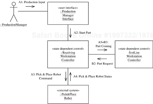
In the communication diagram for the Receive Part abstract use case (Figure 15.30), the receiving workstation controller sends a part to the first line workstation controller. The message sequence is as follows:
A1: The actor, the human production manager, initiates processing of a work order, which necessitates the start of manufacturing each part in the work order.
A2:
Production Manager Interfacesends toReceiving Workstation ControlleraStart Partmessage containing the part type and number of parts to be manufactured.A3:
Receiving Workstation Controllersends a command toPick & Place Robotto place on the conveyor the raw material from which the part is to be manufactured.A4:
Pick & Place Robotplaces the material on the conveyor and notifiesReceiving Workstation Controller.A5 = B3:
Receiving Workstation Controllersends aPart Comingmessage tofirst Line Workstation Controller. This message constitutes the end of the message communication (A5) for theReceive Partcommunication diagram and the next event in the event sequence (B3) of theProcess Part at High-Volume Workstationcommunication diagram.
In the communication diagram for the Process Part at High-Volume Workstation use case (Figure 15.31), Line Workstation Controller n sends a part to Line Workstation Controller n + 1. The following event sequence is shown on both the Process Part at High-Volume Workstation communication diagram (Figure 15.31) and the statechart for Line Workstation Controller (Figure 15.28). The message sequence is as follows:
B1, B2: As explained at the start of this section.
B3: On receiving the
Part Comingmessage from the predecessor workstation,Line Workstation Controllertransitions into thePart Arrivingstate (see Figure 15.28).B4: The action associated with the state transition is that
Line Workstation Controllerissues toWorkflow Plan ServeraNext Operation Requestmessage containing the part type and current workflow step number (initially 1).B5:
Workflow Plan Serverincrements the workflow step number for this part's workflow plan, determines the operation ID for this workflow step, and issues anOperation Requestmessage toManufacturing Operation Serverfor the next operation in sequence.B6:
Manufacturing Operation Serverretrieves the operation information and sends it back.B7:
Workflow Plan Serversends the operation information toLine Workstation Controller.B8: A sensor at
Pick & Place Robotdetects arrival of the part at the workstation and sends aPart Arrivedmessage toLine Workstation Controller. As a result,Line Workstation Controllertransitions to theRobot Pickingstate.B9: As a result of the state transition,
Line Workstation Controllersends a command toPick & Place Robotto pick the part off the conveyor.B10:
Pick & Place Robotpicks the part off the conveyor and places it in the workstation. On completion,Pick & Place RobotnotifiesLineWorkstation Controller.Line Workstation Controllertransitions to theOperating on Partstate.B11:
Line Workstation Controllersends theStart Operationcommand toManufacturing Robot, which operates on the part.B12: On completion of the manufacturing operation,
Manufacturing Robotsends anOperation Endstatus message toLine Workstation Controller. If a part has been requested (C2),Line Workstation Controllertransitions to theRobot Placingstate; if not,Line Workstation Controllertransitions toAwaiting Part Request from Successor Workstation.B13: As a result of the transition to
Robot Placingstate,Line Workstation Controllersends a command toPick & Place Robotto place the part on the conveyor.B14: On completion of its job,
Pick & Place Robotsends aPart Placedmessage toLine Workstation Controller.Line Workstation Controllertransitions toAwaiting Part from Predecessor Workstation. As a result of the transition, two concurrent actions take place: B15 and B15a.B15 = C3:
Line Workstation Controllersends aPart Comingmessage to the successor workstation.Part Comingis an output event on thePart Processingstatechart that is propagated to thePart Requestingorthogonal statechart, where it appears as an input event that causes a transition fromPart Has Been RequestedtoPart Not Requested.B15a (parallel sequence):
Line Workstation Controllersends aPart Requestmessage to the predecessor workstation.
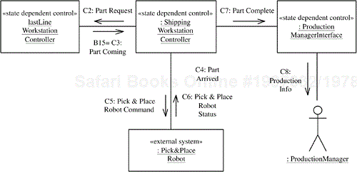
The communication diagram for the Ship Part abstract use case (Figure 15.32), in which last Line Workstation Controller sends a part to Shipping Workstation Controller, consists of the following message sequence (C1, C2, and C3 have been previously described):
C4: At
Shipping Workstation Controller, a sensor detects part arrival and sends thePart Arrivedmessage.C5, C6:
Pick & Place Robotpicks the part off the conveyor and notifiesShipping Workstation Controller.C7:
Shipping Workstation Controllerstores the part in the finished parts inventory and sends aPart Completemessage toProduction Manager Interface.C8:
Production Manager Interfacedisplays the part completion information to the human production manager.
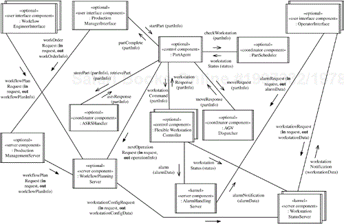
Now consider the communication diagrams for the flexible manufacturing use cases. In the Flexibly Manufacture Part use case, parts released to the factory floor are handled by Part Scheduler, which schedules parts to the various workstations on the basis of workstation availability and the workstation type required, as indicated by the next operation to be processed for that part. To move a part to the workstation, AGV Dispatcher is responsible for ensuring that the part is moved from its current location to the appropriate workstation. When the part has been delivered, Flexible Workstation Controller is informed that the part has arrived. Part Scheduler is informed of the completion of the operation so that it can schedule the part to the next workstation.
Flexible manufacturing systems use an automated storage and retrieval system (ASRS) to store raw material and finished parts. In some flexible manufacturing systems, parts in process are also temporarily stored in the ASRS as described by the Store Part and Retrieve Part extension use cases. In this situation, if all workstations are busy, Part Scheduler may decide to temporarily move the part to the ASRS. AGV Dispatcher is requested to move the part to the ASRS. When the part arrives at the ASRS, ASRS Handler is requested to place the part in storage.
To avoid having overly centralized part scheduling, part processing is divided as follows: Part Scheduler decides which workstation a part should move to next. Part Agent (one object for each part) acts on behalf of the part, making requests to the following objects:
Part Scheduler, when a decision about the next workstation is requiredAGV Dispatcher, when a move to a workstation is required, which interfaces to an external AGV systemASRS Handler, if a move to the ASRS is required, which interfaces to an external ASRSFlexible Workstation Controller, to inform it of the part arriving and to receive part status information
This means that the part processing activity is divided between a decision maker (Part Scheduler) and an implementer of the scheduler's decisions for a given part (Part Agent). Part Agent executes a statechart that represents the part's progress through the factory. This design allows further decentralization, if deemed necessary, because it allows for a Workcell Scheduler, which schedules part processing for a given workcell (a workcell consists of all workstations of a given type). With this alternative design, there is no centralized Part Scheduler.
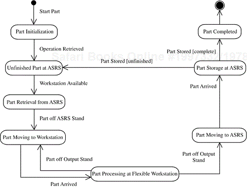
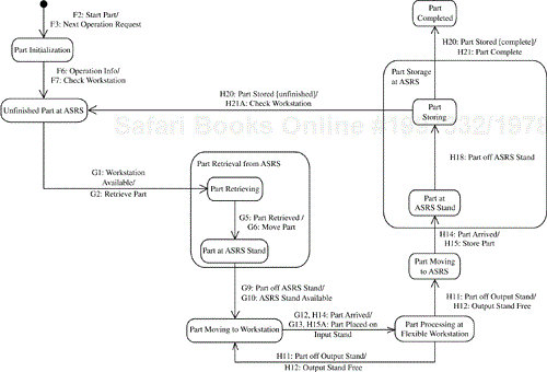
A high-level statechart for the processing of a part in a flexible manufacturing system, which is executed by the Part Agent object, is shown in Figure 15.33 (more detail is provided later, in Figure 15.34). The states are described here. How the Part Agent object transitions between the different states is described in the scenarios in Section 15.6.8.
Part Initialization. Raw material is found for the part from the ASRS, and the first operation for the part is retrieved.Unfinished Part at ASRS. The part is in the ASRS waiting to be dispatched to the next workstation.Part Retrieval from ASRS. The part is in the process of being removed from its bin by the forklift truck and placed on the ASRS stand. This superstate is decomposed into two substates, as shown in Figure 15.34:Part Retrieving. The forklift truck is removing the part from the ASRS warehouse and taking it to the ASRS stand.Part at ASRS Stand. The part has been placed on the ASRS stand by the forklift truck.
Part Moving to Workstation. The part is being moved to the next workstation by an AGV.Part Processing at Flexible Workstation. The part has arrived at the workstation input stand and is being processed at the workstation.Part Moving to ASRS. The part is being moved by an AGV from the workstation output stand to the ASRS stand for storage.Part Storage at ASRS. The part is being taken off the ASRS stand by the forklift truck to be stored in an ASRS bin. This superstate is decomposed into two substates, as shown in Figure 15.34:Part at ASRS Stand. The part has been placed on the ASRS stand by the AGV.Part Storing. The part is being taken to the ASRS by the forklift truck. The forklift truck is removing the part from the ASRS stand and taking it to the ASRS warehouse.
Part Completed. All operations on the part have been completed (or part processing failed), and the completed part has been stored in the ASRS.
A more detailed statechart for Part Agent is given in Figure 15.34, and the substates for the Part Processing at Flexible Workstation superstate are given in Figure 15.35. In each of these statecharts, both the events and the actions are shown.
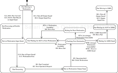
Figure 15.35. Statechart of Part Agent: decomposition of Part Processing at Flexible Workstation superstate
The Part Processing at Flexible Workstation superstate is decomposed into the following states (see Figure 15.35):
Part on Workstation Input Stand. The AGV has placed the part on the input stand.Part Processing. The part is being processed at the workstation.Part on Workstation Output Stand. The part is ready to be removed.Checking Next Destination.Part Agentis determining which workstation is next and whether that workstation is free.Waiting for Next Workstation. The part is on the output stand waiting for a workstation to become free (this state is entered only if the ASRS is unavailable for intermediate storage, as indicated by the feature condition [no storage]).Part Waiting for AGV to Next Workstation. The next workstation is free, and an AGV is coming to take the part to it.Waiting for ASRS Stand. The next workstation is not free, and the part is to be moved to the ASRS once a free stand has been located (this state is entered only if the ASRS is available for intermediate storage, as indicated by the feature condition [storage]).Part Waiting for AGV to ASRS. A free ASRS stand has been located, and an AGV is coming to take the part to the ASRS.
The communication diagrams for the flexible manufacturing use cases are shown in Figures 15.36 through 15.38. Instead of having one large use case, the flexible manufacturing use cases are divided into the following abstract use cases:
Start Work OrderMove Part to WorkstationProcess Part at Flexible WorkstationMove Part from Workstation
Because the use cases are state-dependent, events are shown on both communication diagrams and statecharts. The statecharts are for two particular state-dependent control objects that participate in these use cases: Part Agent and Flexible Workstation Controller. Thus, whenever an event is sent or received by one of these two objects, it is shown on both the communication diagram and the relevant statechart.
The communication diagram for the Start Work Order use case is described first. The production manager is the actor. The software objects participating in this use case are Production Manager Interface, Part Agent, Part Scheduler, Workflow Plan Server, and Manufacturing Operation Server. The communication diagram is shown in Figure 15.36. The message sequence is as follows:
F1: The human production manager creates a work order.
F2:
Production Manager InterfaceinstantiatesPart Agentand sends aStart Partmessage to it.F3:
Part Agentsends aNext Operation Requestmessage toWorkflow Plan Server.F4:
Workflow Plan Serverdetermines the next operation for this part and sends anOperation Requestmessage toManufacturing Operation Server.F5:
Manufacturing Operation Serverresponds with the operation information.F6:
Workflow Plan Serversends the operation information toPart Agent.F7:
Part AgentrequestsPart Schedulerto check if a workstation is available to process the part. If a workstation is available, the communication diagram for theMove Part to Workstationuse case (see Figure 15.37) is initiated. Otherwise the request is added to the queue for workstations of this type.
The communication diagram for the Move Part to Workstation use case is described next (see Figure 15.37). The software objects participating in this use case are Part Scheduler, Part Agent, ASRS Handler, AGV Dispatcher, and Flexible Workstation Controller. There are two external systems: ASRS Forklift Truck and AGV. The message sequence is as follows:
G1:
Part Schedulerdetermines that a workstation is available for the part, either as a result of the F7 request (see Figure 15.36) or because a message arrives indicating that a workstation input stand has become free and this part is at the top of the queue.Part Schedulerreserves the workstation input stand for the part and sends aWorkstation Availablemessage toPart Agent.G2:
Part Agentsends aRetrieve Partmessage toASRS Handler.G3:
ASRS Handlerselects a forklift truck and sends aRetrieve Partmessage toASRS Forklift Truckto fetch the part from the ASRS bin and move it to the ASRS stand.G4:
ASRS Forklift Trucksends a message indicating that the part is on the ASRS stand.G5:
ASRS Handlersends aPart Retrievedmessage toPart Agent. (Part Schedulerdoes not need to know.)G6:
Part Agentsends aMove Part(ASRS stand to workstation x) message toAGV Dispatcher.G7:
AGV Dispatcherselects an AGV and sendsAGVaMove Part(to workstation x input stand) message.G8:
AGVinformsAGV Dispatcherthat the part has been removed from the ASRS stand.G9:
AGV DispatcherinformsPart Agentthat the ASRS stand is available.G10:
Part AgentinformsASRS Handlerthat the ASRS stand is available.G11:
AGVinformsAGV Dispatcherthat the part has arrived at the workstation input stand.G12:
AGV DispatcherinformsPart Agentthat the part has arrived at the workstation input stand. (Part Schedulerdoes not need to know.)G13 = W1:
Part Agentsends aPart Placed on Input Standmessage toFlexible Workstation Controller. (The W sequence is continued in theFlexible Workstation Controllerinteractions depicted in Figure 15.42 and described in Section 15.6.9.)W4 = G14:
Flexible Workstation ControllerinformsPart Agentthat the workstation input stand is free.G15:
Part AgentinformsPart Schedulerthat the workstation input stand is free.Part Scheduleruses this information to schedule another part to this workstation (see step G1 at the start of this sequence).
The communication diagram for the Move Part from Workstation use case is described next (see Figure 15.38). The software objects participating in this use case are Part Scheduler, Part Agent, Production Manager Interface, Workflow Plan Server, Manufacturing Operation Server, ASRS Handler, AGV Dispatcher, and Flexible Workstation Controller. As before, there are two external systems: ASRS Forklift Truck and AGV. The message sequence is as follows:
W10 = H1:
Flexible Workstation Controllersends aPart Completemessage toPart Agent.H2–H5:
Part Agentsends aNext Operation Requestmessage toWorkflow Plan Server. As in steps F3 through F6 (see Figure 15.36),Workflow Plan Serverretrieves the manufacturing operation information, including the workstation type of the next workstation, fromManufacturing Operation Serverand sends it toPart Agent.H6:
Part AgentrequestsPart Schedulerto to check whether a workstation of the required type is available.H7:
Part Schedulerreports toPart Agentthat the required workstation is available, so the part will be moved by an AGV to the next workstation's input stand.H7A: [no storage].
Part Schedulerreports toPart Agentthat the required workstation is unavailable, so the part must wait on the output stand for a workstation to become available. (This variant branch is taken only if the ASRS is unavailable for intermediate storage, as indicated by the feature condition [no storage]).H7A.1:
Part Schedulerreports toPart Agentthat the required workstation has become available, so the part can now be moved by an AGV to the next workstation's input stand.H7B: [storage].
Part Schedulerreports toPart Agentthat the required workstation is unavailable, so the part will be moved to the ASRS. (This variant branch is taken only if the ASRS is available for intermediate storage, as indicated by the feature condition [storage]).H7B.1:
Part Agentsends aReserve Standmessage to ASRS Handler to find an ASRS stand to which the part can be moved.H7B.2:
ASRS Handlerresponds with the ID of a vacant ASRS stand.H8:
Part Agentsends aMove Partmessage toAGV Dispatcherto move the part from the workstation output stand to a destination stand (either the next workstation input stand or an ASRS stand).H9:
AGV Dispatcherselects an AGV and instructs AGV to move the part to the destination stand.H10:
AGVinformsAGV Dispatcherthat the part has been removed from the workstation output stand.H11:
AGV DispatcherinformsPart Agentthat the workstation output stand is available.H12 = W7.1:
Part AgentnotifiesFlexible Workstation Controllerthat the workstation output stand is free.H13:
AGVinformsAGV Dispatcherthat the part has arrived at the destination stand.H14:
AGV DispatcherinformsPart Agentthat the part has arrived at the destination stand.H15A = W1: If the part destination stand is the workstation input stand,
Part AgentinformsFlexible Workstation Controllerthat the part is on the input stand. (This is the end of the sequence for this alternative branch; the W sequence is continued in theFlexible Workstation Controllerinteractions depicted in Figure 15.42 and described in Section 15.6.9).H15: If the part destination stand is the ASRS stand,
Part Agentsends aStore Partmessage toASRS Handler.H16:
ASRS HandlerinstructsASRS Forklift Truckto move the part from the ASRS stand and store it in an ASRS bin.H17:
ASRS Forklift TruckinformsASRS Handlerthat the part is off the ASRS stand.H18:
ASRS HandlerinformsPart Agentthat the part is off the ASRS stand.H19:
ASRS Forklift TruckinformsASRS Handlerthat the part has been moved to an ASRS bin.H20:
ASRS HandlerinformsPart Agentthat the part has been stored.H21A: If this is not the last manufacturing operation of the workflow plan, then
Part AgentrequestsPart Schedulerto check if the next workstation is available.H21: If this is the last manufacturing operation of the workflow plan, then
Part AgentinformsProduction Manager Interfacethat part processing is complete.H22:
Production Manager Interfaceinforms the production manager that part processing is complete.
This section discusses the dynamic modeling for flexible workstation control—first the statechart for the Flexible Workstation Controller class and then the communication diagram for the Process Part at Flexible Workstation use case.
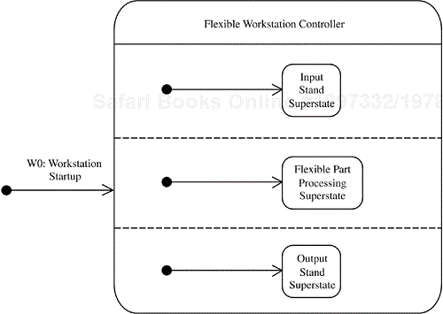
The Flexible Workstation Controller statechart (Figure 15.39) consists of three orthogonal statecharts (Figures 15.40 and 15.41), each of which is depicted as a superstate. The superstates are as follows:
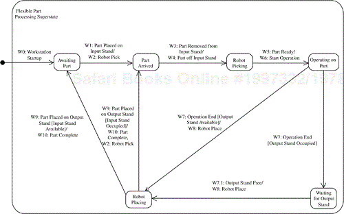
Input Stand Superstate. This superstate consists of two substates:Input Stand AvailableandInput Stand Occupied(see Figure 15.41a).Output Stand Superstate. This superstate consists of two substates:Output Stand AvailableandOutput Stand Occupied(see Figure 15.41b).Flexible Part Processing Superstate. This superstate depicts the different states that a part goes through at a workstation. TheFlexible Part Processingsuperstate contains the following substates (see Figure 15.40). The transitions between the substates are described in the context of the communication diagram (Figure 15.42):Awaiting Part. This is the initial state, in which the workstation is idle, waiting for the arrival of a part.Part Arrived. This state is entered when the workstation receives a message indicating that the next part has been placed on the input stand.Robot Picking.Flexible Workstation Controlleris in this state when pick-and-place robot is picking the part off the input stand and bringing it to the work location.Operating on Part.Flexible Workstation Controllerenters this state when it receives a message indicating that the part is ready at the workstation. The manufacturing robot is operating on the part.Robot Placing. The pick-and-place robot is placing the part on the output stand. This state is entered when the robot operation has been completed and the output stand is available.Waiting for Output Stand. This state is entered when robot manufacturing has been completed but the output stand is not available.
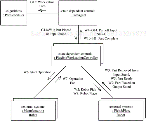
The communication diagram for the Process Part at Flexible Workstation use case is shown in Figure 15.42. The software objects participating in this use case are Flexible Workstation Controller, Part Agent, and Part Scheduler. Two of these—Part Agent and Flexible Workstation Controller—are state-dependent control objects. There are also two external systems: Pick & Place Robot and Manufacturing Robot. The message sequence is as follows (see Figures 15.40 and 15.42):
G13 = W1:
Part AgentinformsFlexible Workstation Controllerthat the part is on the input stand.W2:
Flexible Workstation ControllerrequestsPick & Place Robotto move the part off the input stand.W3:
Pick & Place Robotresponds when it has moved the part off the input stand.W4 = G14:
Flexible Workstation ControllerinformsPart Agentthat the workstation input stand is free.W5:
Pick & Place Robotsends a message toFlexible Workstation Controllerwhen the part has been placed in the workstation and is ready for processing.W6:
Flexible Workstation ControllerrequestsManufacturing Robotto start the manufacturing operation.W7:
Manufacturing RobotinformsFlexible Workstation Controllerwhen the part manufacturing is complete. Depending on whether the output stand is free or not, the state transition is either toRobot Placingstate orWaiting for Output Standstate.H12 = W7.1:
Part AgentnotifiesFlexible Workstation Controllerthat the workstation output stand is free (see Figure 15.38). The statechart transitions toRobot Placingstate.W8:
Flexible Workstation ControllerrequestsPick & Place Robotto move the part to the workstation output stand.W9:
Pick & Place RobotinformsFlexible Workstation Controllerwhen the part is on the workstation output stand.W10 = H1:
Flexible Workstation Controllersends aPart Completemessage toPart Agent. (Part Schedulerdoes not need to know.)
A feature describes a requirement or characteristic that is provided by one or more members of the product line. During this step, feature/class dependencies are determined, describing the classes that support the feature and how they interact. The feature/class dependencies for the factory automation software product line are described in this section and summarized in Table 15.2.
Table 15.2. Feature/class dependencies of the factory automation software product line
Feature Name | Feature Category | Class Name | Class Category |
|---|---|---|---|
Factory Kernel | common | Alarm Handling Server | kernel |
Workstation Status Server | kernel | ||
Workstation Controller | kernel-abstract-vp | ||
Factory Operations User | optional | Operator Interface | optional |
Factory Monitoring | alternative | Monitoring Workstation Controller | variant |
Workflow Management | optional | Workflow Plan Server | optional |
Manufacturing Operation Server | optional | ||
Workflow Planning User | optional | Workflow Engineer Interface | optional |
Work Order Management | optional | Work Order Server | optional |
Part Server | optional | ||
Work Order User | optional | Production Manager Interface | optional |
High-Volume Manufacturing | alternative | Receiving Workstation Controller | variant |
Line Workstation Controller | variant | ||
Shipping Workstation Controller | variant | ||
Flexible Manufacturing | alternative | Part Agent | optional |
Part Scheduler | optional | ||
Flexible Workstation Controller | variant | ||
AGV Dispatcher | optional | ||
ASRS Handler | optional | ||
Storage & Retrieval | optional | Part Scheduler With Storage | variant |
The kernel of the product line consists of those classes that are required by every member of the product line. Thus the classes required to support the common features form the kernel of the product line. The kernel classes of the factory
automation software product line are Alarm Handling Server, Workstation Status Server, and Workstation Controller. In order to accommodate all kinds of factory automation systems, Workstation Controller is designed as a generalized abstract workstation controller class, which needs to be specialized into a specific subclass before it can be instantiated. Workstation Controller is specialized to give the following subclasses: Receiving Workstation Controller, Line Workstation Controller, Shipping Workstation Controller, Flexible Workstation Controller, and Monitoring Workstation Controller, as shown in the generalization/specialization hierarchy in Figure 15.43. In addition to being abstract and a kernel class, Workstation Controller is a variation point, so product line variability can be introduced through specialization of this class.
In order to determine the feature/class dependencies, it is necessary to determine the feature/object dependencies first. Thus it is necessary to analyze the dynamic model by considering the communication diagrams for each use case and the feature/use case dependencies. Start by considering the common feature, Factory Kernel, which relates to the four use cases involving the Factory Operator actor: View Alarms, View Workstation Status, Generate Alarm and Notify, and Generate Workstation Status and Notify (see Figure 15.7). The communication diagrams for these four use cases, created during dynamic modeling of the factory automation product line, are shown in Figures 15.21 through 15.24. The software objects that participate in these communication diagrams are Operator Interface, Alarm Handling Server, Workstation Status Server, and Workstation Controller. These four communication diagrams are integrated into a feature-based generic communication diagram as shown in Figure 15.44.
Because Workstation Controller is an abstract class, it does not have any instances; it is therefore necessary to depict an instance of one of its subclasses. For this exercise, the Monitoring Workstation Controller is chosen because it is the simplest to consider first. Usually the objects that participate in kernel use cases are all kernel objects supporting the Factory Kernel common feature. But because the product line needs to allow for factory systems that do not support a user interface (which is provided instead by an external system), it is necessary to categorize the Operator Interface object as an optional object, which supports a separate optional feature (Factory Operations User), as shown in Figure 15.44. Factory Kernel is supported by the two kernel objects: Alarm Handling Server and Workstation Status Server, which is a multi-instance object. Monitoring Workstation Controller is a variant object that supports the alternative feature Factory Monitoring.
The next step is to develop the feature/class dependencies, which follow directly from the feature-based communication diagram. The common Factory Kernel feature and the optional Factory Operations User feature are shown with the classes that support them in the feature-based class diagram in Figure 15.45, which is determined directly from Figure 15.44. The fact that the optional Factory Operations User feature depends on the common Factory Kernel feature is shown by the Is Client of association between the optional Operator Interface class and the kernel Alarm Handling Server and Workstation Status Server classes. Figure 15.45 also depicts the Factory Monitoring feature, which is an alternative feature because it is mutually exclusive with the High-Volume Manufacturing and Flexible Manufacturing features. The Factory Monitoring feature is supported by the variant Monitoring Workstation Controller class, which is a specialized subclass of the Workstation Controller kernel superclass, as shown in Figure 15.45. Thus a superclass can support one feature and be a kernel class while its variant subclasses support different features.
Next, consider the optional use cases initiated by Workflow Engineer—that is, Create/Update Operation and Create/Update Workflow Plan (see Figure 15.4). As described in Section 15.3, these use cases are organized into two features: Workflow Management and Workflow Planning User. The communication diagram for the two use cases is depicted in Figure 15.25, which shows four objects: Workflow Engineer Interface, Workflow Plan Server, Manufacturing Operation Server, and Workstation Status Server. Of these four objects, Workstation Status Server has already been categorized as a kernel object. The other three objects are all categorized as optional objects. Because of the need for factory systems without a user interface, however, Workflow Engineer Interface is allocated to a different feature (Workflow Planning User) than the remaining two server objects (Workflow Plan Server and Manufacturing Operation Server), which are allocated to the Workflow Management feature, as shown in the feature-based communication diagram in Figure 15.46.
Consider the optional use case initiated by Production Manager: Create/Modify Work Order. This use case is supported by the communication diagram shown in Figure 15.26. Of the four objects depicted there, Workflow Plan Server has already been allocated to the Workflow Management feature. Following a similar approach to that taken for the Workflow Engineer features, Work Order Server and Part Server are categorized as optional objects that are allocated to the optional Work Order Management feature, and Production Manager Interface is categorized as an optional object allocated to the optional Work Order User feature. The feature-based class diagram for all these features (Figure 15.47) is determined directly from the feature-based communication diagram (Figure 15.46).
Consider how the workflow and work order features (those initiated by Workflow Engineer and Production Manager) are used in flexible and high-volume manufacturing systems. The Workflow Planning User and Work Order User features are optional because it is possible to have a system in which workflow plans and work orders are downloaded from an external system and are not created or modified on this system. Of the optional classes shown in Figure 15.47, the server classes (namely, Workflow Plan Server and Manufacturing Operation Server) are always required by flexible and high-volume manufacturing systems and therefore should be kept separate from the client class Workflow Engineer Interface, which is required only sometimes. Thus a Workflow Management feature that includes the Workflow Plan Server and Manufacturing Operation Server classes is defined. This optional class, called Workflow Engineer Interface, is kept separate and is placed in the Workflow Planning User feature.
Now consider the feature/class dependencies that apply to only one kind of factory system. Classes that have already been allocated to kernel and optional features in the previous sections are factored out. For feature/class dependencies determined from the High-Volume Part Processing communication diagrams, the classes Production Manager Interface, Workflow Plan Server, and Manufacturing Operation Server are factored out because they are already in the workflow and work order features. Similarly, for feature/class dependencies determined from the Flexibly Manufacture Part communication diagram, the same three classes are factored out.
Consider the communication diagrams for the high-volume manufacturing use cases. There are four use cases, consisting of one concrete use case (Manufacture High-Volume Part) that includes three abstract use cases (Receive Part, Process Part at High-Volume Workstation, and Ship Part), which are are mapped to the alternative High-Volume Manufacturing feature, as shown in Figure 15.9. The abstract use cases contain all the functionality. The communication diagrams for these use cases are shown in Figures 15.30 through 15.32. The communication diagram for the Receive Part use case has the Production Manager Interface, Receiving Workstation Controller, and Line Workstation Controller objects (see Figure 15.30). The communication diagram for the Process Part at High-Volume Workstation use case has the Line Workstation Controller, Workflow Plan Server, and Manufacturing Operation Server objects (see Figure 15.31). The communication diagram for the Ship Part use case has the Line Workstation Controller, Shipping Workstation Controller, and Production Manager Interface objects (see Figure 15.32 ).
An integrated communication diagram would normally include all the objects from the three use case–based communication diagrams. In the feature-based communication diagram (Figure 15.48), however, the objects that appear in prerequisite communication diagrams are removed. In particular, the Workflow Plan Server, Manufacturing Operation Server, and Production Manager Interface objects are assigned to prerequisite communication diagrams and are thus removed from the feature-based communication diagram for the High-Volume Manufacturing feature. The remaining objects supporting this feature are Receiving Workstation Controller, Line Workstation Controller, and Shipping Workstation Controller.
The feature-based class diagram (Figure 15.49) is determined from the feature-based communication diagram in Figure 15.48. The class diagram also shows the abstract superclass Workstation Controller, from which the three subclasses Receiving Workstation Controller, Line Workstation Controller, and Shipping Workstation Controller are derived.
Now consider the flexible manufacturing use cases, which support the alternative Flexible Manufacturing feature, as shown in Figure 15.10. The Flexibly Manufacture Part use cases (Start Work Order, Move Part to Workstation, Process Part at Flexible Workstation, and Move Part from Workstation) are mapped to the Flexible Manufacturing feature.
The communication diagrams for the flexible manufacturing use cases are shown in Figures 15.36 through 15.38. The feature-based communication diagram is created by integration of the individual flexible manufacturing communication diagrams and then removal of the objects that have already been allocated to other kernel and optional features—following the approach used in the previous section for the High-Volume Manufacturing feature. The result is shown in Figure 15.50, where all the objects are categorized as optional except for Flexible Workstation Controller, which is a variant class because it is a subclass of Workstation Controller. Further analysis indicates that it is possible for a flexible manufacturing system either to support intermediate storage and retrieval, in which parts are temporarily stored in the ASRS, or not. This refinement leads to two features: Flexible Manufacturing and Storage & Retrieval.
The classes supporting the former feature are Part Scheduler, AGV Dispatcher, Flexible Workstation Controller, Part Agent, and ASRS Handler. The feature-based class diagram for this feature is shown in Figure 15.51.
The Store Part and Retrieve Part extension use cases are mapped to the Storage & Retrieval feature, which is supported by the specialized Part Scheduler With Storage class. The feature-based class diagram for this feature is shown in Figure 15.52.
Storage & Retrieval is an optional feature that requires Flexible Manufacturing as a prerequisite. However, it is also necessary to extend Part Scheduler (which now needs to schedule trips to and from the ASRS) and Part Agent (whose statechart needs to be extended to allow ASRS handling). This extension of functionality could be handled by specialization: having ASRS variants of Part Scheduler and Part Agent. Alternatively, it could be handled by parameterization, meaning that the ASRS functionality is built into the components from the start and then the feature conditions [storage] and [no storage] are used. If the feature condition were set to [no storage], Part Scheduler would never schedule a part to the ASRS; otherwise, if the feature condition were set to [storage], it would. If a part were never scheduled to the ASRS, those states in Part Agent would never be entered. The solution adopted is to use parameterization for Part Agent because the feature conditions [storage] and [no storage] (as depicted on the statechart in Figure 15.35) determine whether or not a part is moved to the ASRS when a workstation is unavailable. Specialization is used for Part Scheduler because the scheduling algorithm needs to be extended to handle intermediate scheduling to the ASRS.
Figure 15.45 shows the static model for the Factory Monitoring feature together with the Factory Kernel feature and the Factory Operations User feature. Grouped together, these three features form the Factory Monitoring System, which is one of the target systems of the factory automation product line. The Monitoring Workstation Controller class in the Factory Monitoring feature is a specialization of the Workstation Controller class in the Factory Kernel feature.
The software architecture for the factory automation software product line is designed as a distributed component-based architecture that applies the software architectural patterns described in Chapter 10. The product line architecture is designed as a layered architecture based on the Layers of Abstraction architectural pattern. The kernel of the product line is designed as the lowest layer of the architecture.
Applying the component structuring criteria, the following components are determined:
Server components. The server components are
Alarm Handling Server,Workstation Status Server,Workflow Planning Server(which is a composite component composed of theWorkflow Plan ServerandManufacturing Operation Serverclasses), andProduction Management Server(a composite component composed of theWork Order ServerandPart Serverclasses).User interface components. The user interface components are
Operator Interface,Workflow Engineer Interface, andProduction Manager Interface.Control components. The control components are all the variant
Workstation Controllercomponents (as shown in Figure 15.43) andPart Agent.Part Agentis redesigned as a composite component that contains simple agents (one for each part).Coordinator components. The coordinator components are
Part Scheduler,AGV Dispatcher, andASRS Handler.
Each component is depicted with two stereotypes: the component stereotype (what kind of component it is, as specified by the component structuring criteria) and the product line stereotype (the reuse category—kernel, optional, or variant). The components are structured into the layered architecture such that each component is in a layer where it needs the service provided by components in the layers below but not the layers above. This layered architecture is based on the Flexible Layers of Abstraction pattern, which is a less restrictive variant of the Layers of Abstraction pattern in which a layer can use the services of any of the layers below it, not just the layer immediately below it. This layered architecture, depicted in Figure 15.53, facilitates adaptation of the factory automation software product line architecture to derive individual application members of the product line:
Layer 1:
Kernel Server Layer. This layer consists of the kernel server components:Alarm Handling ServerandWorkstation Status Server. This layer constitutes the kernel of the product line following the Kernel pattern.Layer 2:
Workflow Server Layer. This layer consists of the optionalWorkflow Planning Servercomponent. It requires theWorkstation Status Servercomponent from theKernel Server Layer.Layer 3:
Production Server Layer. This layer consists of the optionalProduction Management Servercomponent. It requires theWorkflow Planning Servercomponent from theWorkflow Server Layer.Layer 4:
Distributed Control Layer. This layer consists of the variant and optional control components that provide distributed control, includingAGV Dispatcher,ASRS Handler, and the followingWorkstation Controllervariants:Monitoring Workstation Controller,Line Workstation Controller,Receiving Workstation Controller,Shipping Workstation Controller, andFlexible Workstation Controller. All of theWorkstation Controllercomponents requireAlarm HandlingServerandWorkstation Status Serverfrom layer 1.Line Workstation Controlleralso requiresWorkflow Planning Serverfrom layer 2.Layer 5:
Hierarchical Control Layer. This layer consists of the optional control and coordinator components that provide hierarchical control:Part AgentandPart Scheduler.Part AgentrequiresFlexible Workstation Controller,AGV Dispatcher, andASRS Handler(all from theDistributed Control Layer);Workflow Planning Server(from theWorkflow Server Layer), andPart Scheduler(from the same layer).Layer 6:
User Interface Layer. This layer consists of the optional user interface components:Operator Interface,Workflow Engineer Interface, andProduction Manager Interface.Operator InterfacerequiresAlarm Handling ServerandWorkstation Status Serverfrom layer 1.Workflow Engineer InterfacerequiresWorkflow Planning Serverfrom layer 2.Production Manager InterfacerequiresProduction Management Server(from layer 3),Part Agent(from layer 5),Receiving Workstation Controller, andShipping Workstation Controller(both from layer 4).

Figure 15.53. Layered architecture of the factory automation software product line (Note: Layers are compressed due to page size.)
If two layers do not depend on each other, such as layers 3 and 4 above, the choice of which layer should be higher is a design decision. In addition to the Layers of Abstraction and Kernel architectural patterns, several other architectural structure patterns are applied in the factory automation software product line architecture:
Client/Server pattern. There are several client user interface/server and client control/server interactions in the architecture. In the Layers of Abstraction architecture, client components are designed to be at higher layers than the servers that they require. With the Flexible Layers of Abstraction architecture, a client can be at any of the higher levels. For example,
Operator Interface, which is a client user interface component, is at layer 6, whereas the servers it uses (Alarm Handling ServerandWorkstation Status Server), are at layer 1.Distributed Control pattern. In high-volume manufacturing systems, control is distributed among several control components that are at the same layer of the architecture (layer 4). These are
Receiving Workstation Controller, several instances ofLine Workstation Controller, andShipping Workstation Controller.Hierarchical Control pattern. In flexible manufacturing systems, there are two layers of control. At the lower layer (layer 4) are
AGV Dispatcher,ASRS Handler, and multiple instances ofFlexible Workstation Controller. At the higher layer (layer 5) arePart AgentandPart Scheduler. On the basis of manufacturing workstation availability,Part Schedulerdetermines which workstation a part should be moved to next or whether it should be moved to the ASRS for temporary storage.Part Agentthen implements this decision by communicating withAGV Dispatcher,ASRS Handler, and the specificFlexible Workstation Controllercomponents.
The major application systems that can be derived from the factory automation software product line architecture are shown in Figures 15.54 through 15.56. These are the static models for factory monitoring systems, high-volume manufacturing systems, and flexible manufacturing systems, respectively. The dependencies between the components are determined by the Layers of Abstraction architecture and are depicted in detail in the static models.

Figure 15.56. Static model of a flexible manufacturing system. (Note: Layers are compressed due to page size.)
The class diagram for the factory monitoring system (Figure 15.54) is developed from the layered architecture of the product line in Figure 15.53, combined with consideration of the components needed by the relevant features in this system. The components and relationships are determined from the corresponding communication diagrams (Figures 15.21–15.24) and the feature/class diagram in Figure 15.45, which incorporates components from the Factory Kernel, Factory Monitoring, and Factory Operations User features. Four executable components and three layers are involved. Both Monitoring Workstation Controller and Operator Interface are clients of the kernel Workstation Status Server and Alarm Handling Server components.
The class diagram for the high-volume manufacturing system (Figure 15.55) has five layers and ten components. In addition to kernel components from Figure 15.45, this architecture incorporates components from the workflow and work order features of Figure 15.47 and the High-Volume Manufacturing feature of Figure 15.49. The Production Management Server component in Figure 15.55 is a composition of Work Order Server and Part Server from Figure 15.47, and the Workflow Planning Server component is a composition of Workflow Plan Server and Manufacturing Operation Server.

Figure 15.55. Static model of a high-volume manufacturing system. (Note: Layers are compressed due to page size.)
The class diagram for the flexible manufacturing system (Figure 15.56) has six layers and twelve components. In addition to kernel components from Figure 15.45, this architecture incorporates components from the workflow and work order features of 15.47 and the Flexible Manufacturing feature of Figure 15.51.
The generic concurrent communication diagrams shown in Figures 15.57 through 15.59 depict the major application systems that can be derived from the factory automation software product line architecture. These diagrams are for factory monitoring, high-volume manufacturing, and flexible manufacturing systems, respectively. The diagrams depict the components structured according to the Layers of Abstraction architecture, but they omit the layer packages to make the communication between components clearer. The concurrent communication diagrams explicitly show the type of message communication—synchronous or asynchronous.
The components in the concurrent communication diagram for the factory monitoring system (Figure 15.57) are determined directly from the components in the class diagram in Figure 15.54. The communication between these components is determined from the communication diagrams in Figures 15.21 through 15.24 and the feature-based communication diagram of Figure 15.44, which show the messages passed between the components. Because of the client/server communication, the communication patterns used are Synchronous Message Communication with Reply and Subscription/Notification.
The concurrent communication diagram for the high-volume manufacturing system (Figure 15.58) is determined from the components in the class diagram in Figure 15.55 and the communication diagrams that support the high-volume manufacturing use cases (Figures 15.30–15.32), which show the messages passed between these components. This architecture adds asynchronous message communication between the distributed control components.
The communication diagram for the flexible manufacturing system (Figure 15.59) is determined from the components in the class diagram in Figure 15.56 and the communication diagrams that support the flexible manufacturing use cases (Figures 15.36–15.38), which show the messages passed between these components. This architecture also uses a combination of patterns, with asynchronous communication between the control and coordinator components.
To handle the variety of communication between the components in the software product line architecture, several communication patterns are applied, as depicted on the communication diagrams in Figures 15.57 through 15.59:
Asynchronous Message Communication. The different
Workstation Controllervariants all send asynchronous messages toAlarm Handling ServerandWorkstation Status Server(as shown in all three figures: 15.57 through 15.59). The reason for asynchronous communication is that theWorkstation Controllercomponents need to post alarms and workstation status on a regular basis, they need to continue executing without delay, and they do not need a response.Bidirectional Asynchronous Message Communication. In high-volume manufacturing systems, each high-volume workstation controller communicates with its two neighbors, the predecessor workstation controller (
ReceivingorLine) and the successor workstation controller (LineorShipping) via asynchronous messages (see Figure 15.58). A givenWorkstation Controllercomponent sends an asynchronousPart Requestmessage to its predecessor and then later receives an asynchronousPart Comingmessage from the predecessor. The messages are asynchronous to allow these two components to communicate with other components during the period when they are also communicating with each other.Synchronous Message Communication with Reply. This is the typical client/server pattern of communication and is used when the client needs information from the server and cannot proceed before receiving the response. This pattern is used between the user interface clients and servers. For example, it is used between
Workflow Engineer InterfaceandWorkflow Planning Server, as well as betweenProduction Manager InterfaceandProduction Management Server(see Figures 15.58 and 15.59).Broker Handle. Broker patterns are used during system initialization. Servers register their services and locations with the broker. The Broker Handle pattern allows clients to query the broker to determine the servers to which they should be connected. Workstation controllers also use the Broker Handle pattern to determine the remote references of their neighbors.
Subscription/Notification (Multicast).
Operator Interfacehas two patterns of communication withAlarm Handling ServerandWorkstation Status Server(see Figures 15.57, 15.58, and 15.59). The first is the regular client/server Synchronous Message Communication with Reply pattern, which is used to make alarm requests and receive responses. The second pattern is the Subscription/Notification pattern, in whichOperator Interfacesubscribes to receive alarms of a certain type (e.g., high-priority alarms). When the workstation controller posts an alarm of that type toAlarm Handling Server, the server notifies all subscriberOperator Interfacecomponents of the new alarm. The same approach is used for communication withWorkstation Status Server.
The software architecture of each of the main factory automation systems is depicted in Figures 15.60 through 15.62. All the concurrent components communicate through ports. The ports are provided ports that support provided interfaces, required ports that support required interfaces, or complex ports that support both provided and required interfaces. The interfaces are explicitly depicted in subsequent figures. By convention, the name of a port with a provided interface starts with the prefix P (e.g., PAlarmServer), and the name of a port with a required interface starts with the prefix R (e.g., RAlarmServer).
The software architecture of the factory monitoring system (Figure 15.60) depicts two server components that each support one provided port with a provided interface and one complex port with provided and required interfaces. The two client components each support one required port with a required interface and one complex port with provided and required interfaces. In this architecture, it is Monitoring Workstation Controller that sends alarm status and workstation status messages to Alarm Handling Server and Workstation Status Server, respectively.
In the software architecture of the high-volume manufacturing system (Figure 15.61), three different workstation controllers (Receiving, Line, and Shipping) send alarm status and workstation status messages to Alarm Handling Server and Workstation Status Server, respectively. The multiple instances of the Workstation Controller components are connected in series so that they can provide distributed control. For greatest flexibility, each Line Workstation Controller component has a required port to communicate with its predecessor and a provided port to communicate with its successor. The Receiving Workstation Controller component has only a provided port, and the Shipping Workstation Controller component has only a required port.
In the software architecture of the flexible manufacturing system (Figure 15.62), Part Agent and Part Scheduler together provide the hierarchical control, controlling the lower-level Flexible Workstation Controller, AGV Dispatcher, and ASRS Handler objects. The lower-level controllers have provided ports to receive the commands sent by Part Agent through its corresponding required ports.
The interfaces for the individual components are depicted in Figures 15.63 through 15.75. For each component port, the required and/or provided interface used by that port is depicted. In addition, the operations provided by each interface are specified. Consider an example of a server component with its ports, interfaces, and operations; consider also the clients that communicate with this server. The example is the Alarm Handling Server component, which has two ports: PAlarmStatus and PAlarmServer (as shown in Figure 15.63). The PAlarmStatus port consists of one provided interface called IAlarmStatus, which provides one operation, called post Alarm. The PAlarmServer port has one provided interface (IAlarmServer) and one required interface (IAlarmNotification). The interfaces and operations are specified as follows:
These interfaces are used as follows:
The
Operator Interfacecomponent (depicted in Figures 15.60 through 15.62) uses theIAlarmServerrequired interface (see Figure 15.75) via theRAlarmServercomplex port to send alarm requests and subscriptions toAlarm Handling Server.The
Workstation Controllercomponents (depicted in Figures 15.60 through 15.62) use theIAlarmStatusrequired interface via theRAlarmStatusrequired port (e.g., see Figure 15.66) to post new alarms atAlarm Handling Server.The
Alarm Handling Servercomponent (depicted in Figures 15.60 through 15.62) sends alarm notifications to theOperator Interfacecomponent by using itsIAlarmNotificationrequired interface via thePAlarmServercomplex port (see Figure 15.63).
In Figures 15.63 through 15.75, each component is depicted with both its ports and its provided and required interfaces. Each interface is explicitly depicted in terms of the operations it provides. Each operation specifies its name, input parameters, and output parameters.
In order to derive a factory automation application from the factory automation software product line architecture and components, it is necessary to start with the feature model, which is depicted in Figure 15.11 and Table 15.1. There is also a feature group constraint in the form of an exactly-one-of feature group:
«exactly-one-of feature group» Factory Management {alternative =
Factory Monitoring, High-Volume Manufacturing, Flexible Manufacturing}
Software applications that can be derived from the factory automation product line architecture include high-volume manufacturing, flexible manufacturing, flexible manufacturing with storage, and factory monitoring applications, with possible smaller variations within each of these systems. These applications are derived from the product line architecture by selection of the High-Volume Manufacturing feature, the Flexible Manufacturing feature, the Storage & Retrieval feature, and the Factory Monitoring feature, respectively. The reason that each application can be derived by selection of only one feature is clear from Figure 15.11, which shows that, because of the feature dependencies, each of these four features depends on other features. Table 15.1 shows the feature/use case dependencies; Table 15.2 shows the feature/class dependencies.
To derive a factory system, it is necessary to choose among the High-Volume Manufacturing, Flexible Manufacturing, and Factory Monitoring features. One and only one of the corresponding features can be chosen. For this example, the High-Volume Manufacturing feature is selected. This feature mutually includes the Work Order Management implicit feature, which in turn mutually includes the Workflow Management implicit feature. An implicit feature cannot be selected on its own; it must be selected in conjunction with an explicit feature that requires it.
To derive a high-volume manufacturing system, the application engineer would need to select the High-Volume Manufacturing feature. This feature depends on the Work Order Management feature, which in turn depends on the Workflow Management feature. The common feature Factory Kernel is implicitly required by all optional features. Assume that the application engineer also selects the Factory Operations User, Workflow Planning User, and Work Order User features. The resulting high-volume manufacturing system would then have the following features:
«common feature» Factory Kernel
«optional feature» Factory Operations User {prerequisite = Factory Kernel}
«optional feature» Workflow Management {prerequisite = Factory Kernel}
«optional feature» Workflow Planning User {prerequisite = Workflow Management}
«optional feature» Work Order Management {mutually includes = Workflow Management}
«optional feature» Work Order User {prerequisite = Work Order Management}
«alternative feature» High-Volume Manufacturing {mutually includes = Work Order Management}
Consider the feature/class dependencies shown in Table 15.2, tailored to contain only the features selected for the high-volume manufacturing application and the classes that support these features, as shown in Table 15.3.
Table 15.3. Feature/class dependencies of a high-volume manufacturing system
Feature Name | Feature Category | Class Name | Class Category |
|---|---|---|---|
Factory Kernel | common | Alarm Handling Server | kernel |
Workstation Status Server | kernel | ||
Workstation Controller | kernel-abstract-vp | ||
Factory Operations User | optional | Operator Interface | optional |
Workflow Management | optional | Workflow Plan Server | optional |
Manufacturing Operation Server | optional | ||
Workflow Planning User | optional | Workflow Engineer Interface | optional |
Work Order Management | optional | Work Order Server | optional |
Part Server | optional | ||
Work Order User | optional | Production Manager Interface | optional |
High-Volume Manufacturing | alternative | Receiving Workstation Controller | variant |
Line Workstation Controller | variant | ||
Shipping Workstation Controller | variant |
The static model for the high-volume manufacturing system is depicted in Figure 15.55, the dynamic model is depicted in Figure 15.58, and the software architecture is depicted in Figure 15.61. The deployment diagram for the high-volume manufacturing system is depicted in Figure 15.76.


