Finite state machines are used for modeling the control and sequencing view of a system. Many systems, such as real-time systems, are highly state-dependent. That is, their actions depend not only on their inputs but also on what has previously happened in the system. Notations used to define finite state machines are the state transition diagram, statechart, and state transition table. In highly state-dependent systems, these notations can help substantially by providing a means of understanding the complexity of these systems.
In the UML notation, a state transition diagram is referred to as a statechart diagram. The UML statechart diagram notation is based on Harel's statechart notation (Harel 1988; Harel and Politi 1998). In this book the terms statechart and statechart diagram are used interchangeably. We refer to a traditional state transition diagram, which is not hierarchical, as a flat statechart and use the term hierarchical statechart to refer to the concept of hierarchical state decomposition. A brief overview of the statechart notation is given in Appendix A (Section A.6).
This chapter describes how to develop finite state machines (also referred to as just state machines) and statecharts for software product lines. Although statecharts can be used to model different perspectives of a system, such as the different states of a state-dependent use case (Gomaa 2000), the best use of statecharts in software product lines is for modeling state-dependent classes and objects. In particular, each state-dependent control class—whether kernel, optional, or variant—needs to be modeled with a finite state machine and depicted as a statechart. It is also possible to model variability in a software product line by using inherited state machines and parameterized state machines.
In dynamic interaction modeling, as described in Chapter 7, if the object interaction is state-dependent, then a state-dependent control object is needed, which executes a statechart. The state-dependent interactions are much clearer to understand if the corresponding events are depicted on both the statechart and the interaction diagram.
This chapter starts in Section 8.1 with a description of the finite state machines for the kernel system of software product lines, which is similar to the design of finite state machines for single systems. Section 8.2 then describes the hierarchical decomposition of statecharts, a unique capability that distinguishes statecharts from state transition diagrams. Section 8.3 considers developing finite state machines for software product lines. Two approaches to modeling variability are described: Section 8.4 describes inherited state machines in software product lines, Section 8.5 describes parameterized state machines in software product lines, and Section 8.6 compares the two approaches. The discussion then returns to a theme first introduced in Chapter 7—namely, dynamic analysis using interaction models—except that the treatment in this chapter is of state-dependent dynamic analysis, in which both statecharts and interaction diagrams are depicted. The kernel first approach to state-dependent dynamic analysis is described in Section 8.7, and the product line evolution approach is described in Section 8.8. Finally, Section 8.9 describes dynamic analysis with communicating state-dependent objects.
A finite state machine (also referred to as just state machine) is a conceptual machine with a finite number of states. It can be in only one of the states at any specific time. A state transition is a change in state that is caused by an input event. In response to an input event, the finite state machine might transition to a different state. Alternatively, the event may have no effect, in which case the finite state machine remains in the same state. The next state depends on the current state, as well as on the input event. Optionally, an output action may result from the state transition.
Although a whole system can be modeled by means of a finite state machine, in object-oriented analysis and design a finite state machine is encapsulated inside one object. In other words, the object is state-dependent and is always in one of the states of the finite state machine. The object's finite state machine is depicted by means of a statechart. In an object-oriented model, the state-dependent aspects of a system are defined by means of one or more finite state machines, where each finite state machine is encapsulated inside its own object. This section briefly reviews the basic concepts of events and states before giving some examples of statecharts.
An event is an occurrence at a point in time; it is also known as a discrete signal or stimulus. An event is an atomic occurrence (not interruptible) and conceptually has zero duration. Examples of events are ATM Card Inserted, Part Removed, Part Placed, Brake Pressed, and Elevator Departed.
A timer event is a special event, specified by the keyword after, which indicates that an event occurs after an elapsed time identified by an expression in parentheses, such as after (10 seconds) or after (elapsed time). On a statechart, the timer event causes a transition out of a given state. The elapsed time is measured from the time of entry into that state until exit from the state, which is caused by the timer event.
A state represents a recognizable situation that exists over an interval of time. Whereas an event occurs at a point in time, a finite state machine is in a given state over an interval of time. The arrival of an event at the finite state machine usually causes a transition from one state to another. Alternatively, an event can have a null effect, in which case the finite state machine remains in the same state. In theory, a state transition is meant to take zero time to occur. In practice, the time for a state transition to occur is negligible compared to the time spent in the state.
The initial state of a statechart is the state that is entered when the statechart is activated.
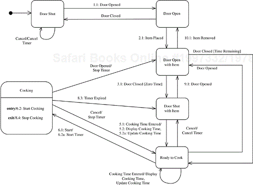
As an example of a statechart, consider the Microwave Oven Control kernel statechart, which is taken from the microwave oven product line case study and shown in Figure 8.1. The statechart follows the sequencing described in the Cook Food use case (see Chapter 13) and shows the different states for cooking food. The initial state is Door Shut. When the user opens the door, the statechart transitions into the Door Open state. The user places an item in the oven, causing the statechart to transition into the Door Open with Item state. When the user closes the door, the statechart then transitions into the Door Shut with Item state. After the user inputs the cooking time, the Ready to Cook state is entered. When the user presses the Start button, the statechart transitions into the Cooking state. When the timer expires, the Door Shut with Item state is reentered. If instead the door were opened during cooking, the Door Open with Item state would be entered. Another possibility is for the user to press the Cancel button during cooking, in which case the Ready to Cook state is entered.
In the microwave oven product line, the Microwave Oven Control kernel object executes the statechart shown in Figure 8.1. The sequence numbers in Figure 8.1 correspond to the main sequence of events and actions for the Cook Food kernel communication diagram, as explained in Section 8.7.
Events and guard conditions may be combined in defining a state transition. The notation used is Event [Condition]. Thus an event is allowed to cause a state transition, provided that the guard condition given in parentheses is true. Conditions are optional.
In some cases an event does not cause an immediate state transition, but its impact needs to be remembered because it will affect a future state transition. The fact that an event has occurred can be stored as a condition that can be checked later.
Examples of guard conditions in Figure 8.1 are Zero Time and Time Remaining. The two transitions out of the Door Open with Item state are Door Closed [Zero Time] and Door Closed [Time Remaining]. Thus the transition taken depends on whether the user has entered the time or not. If the condition Zero Time is true, the statechart transitions to Door Shut with Item, waiting for the user to enter the time. If the condition Time Remaining is true, the statechart transitions to the Ready to Cook state.
Associated with a state transition is an optional output action. An action is a computation that executes as a result of a state transition. An action is triggered at a state transition. It executes and then terminates itself. The action executes instantaneously at the state transition; thus, conceptually an action is of zero duration. In practice, the duration of an action is very small compared to the duration of a state.
To show an action on a statechart, the state transition is labeled Event/Action or Event [Condition]/Action. For example, when the microwave oven transitions from Ready to Cook state back to Door Shut with Item state as a result of the Cancel input event (because the user pressed the Cancel button), the action Cancel Timer is executed (see Figure 8.1). This state transition is labeled Cancel/Cancel Timer. More than one action may be associated with a transition. The actions all execute simultaneously; consequently, they must not have any interdependencies.
Certain actions may also be depicted more concisely as being associated with the state rather than with the transition into or out of the state. These are entry and exit actions, which are represented by the reserved words entry and exit. An entry action is depicted as entry/Action and is an instantaneous action that is performed on entry to the state. An exit action is depicted as exit/Action and is an instantaneous action that is performed on exit from the state.
Examples of entry and exit actions are given in Figure 8.1. If the Start button is pressed (resulting in the Start event) while the microwave oven is in the Ready to Cook state, the statechart transitions to the Cooking state. One transition action, Start Timer, is executed; and one entry action, Start Cooking, is also executed. If the timer expires, or the Cancel button is pressed, or the door is opened, the oven will transition out of the Cooking state. In all these cases, the exit action is Stop Cooking. Having the action as an exit action instead of an action on the state transition is more concise. The alternative of having transition actions would require the action to be explicitly depicted on each of the state transitions out of the Cooking state.
In addition to actions, it is possible to have an activity executed as a result of a state transition. An activity is a computation that executes for the duration of a state. Thus, unlike an action, an activity executes for a finite amount of time. An activity is enabled on entry into the state and disabled on exit from the state. Enable and disable actions always come in pairs. The cause of the state change, which results in disabling the activity, is usually an input event from a source that is not related to the activity. In some cases, however, the activity itself generates the event that causes the state change.
One way to depict an activity on the statechart is to label the transition into the state in which the activity executes as Event/enable Activity and the transition out of the state as Event/disable Activity. However, it is more concise not to show the enable and disable actions on the transitions and instead to show the activity as being associated with the state, by depicting the activity in the state box with a dividing line between the state name and the activity name. The activity is shown as do/Activity, where do is a reserved word. This means that the activity is enabled on entry into the state and disabled on exit from the state.
For examples of activities, consider the Cruise Control statechart shown in Figure 8.2. Initially the statechart is in the Idle state. When the driver switches the ignition switch on, the Engine On event occurs and the Cruise Control statechart transitions to the Initial state. When the driver engages the cruise control lever in the ACCEL position, the Accel event occurs and the statechart transitions to the Accelerating state. During this state, the statechart executes the Increase Speed activity shown on Figure 8.2 as do/Increase Speed. In the Accelerating state, when the driver releases the cruise control lever, the Cruise event occurs, and the statechart transitions to the Cruising state, disabling the Increase Speed activity and enabling the Maintain Speed activity. The statechart executes the Maintain Speed activity for the duration of the Cruising state. If the driver places his/her foot on the brake, the Brake Pressed event occurs, and the statechart transitions to the Cruising Off state, disabling Maintain Speed. If the driver later engages the cruise control lever in the RESUME position, the Resume event occurs and the statechart transitions to the Resuming state. During this state, the statechart executes the Resume Cruising activity. When the car reaches the cruising speed, the statechart reenters the Cruising state, disabling the Resume Cruising activity and enabling the Maintain Speed activity.
One of the potential problems of flat statecharts is the proliferation of states and transitions, which makes the statechart very cluttered and difficult to read. A very important way of simplifying statecharts and increasing their modeling power is to introduce superstates and the hierarchical decomposition of statecharts. With this approach, a superstate (also known as a composite state) at one level of a statechart is decomposed into several substates on a lower-level statechart.
The objective of hierarchical statecharts is to exploit the basic concepts and visual advantages of state transition diagrams while overcoming the disadvantages of overly complex and cluttered diagrams through hierarchical structuring. Note that any hierarchical statechart can be mapped to a flat statechart, so for every hierarchical statechart there is a semantically equivalent flat statechart.
Hierarchical state machines are useful for modeling variability in software product lines. This section describes hierarchical state machine concepts before describing the two main approaches to introducing state machine variability into product lines: inheritance and parameterization.
Statecharts can often be significantly simplified by the hierarchical decomposition of states, in which a superstate is decomposed into two or more interconnected sequential substates. This kind of decomposition is referred to as sequential state decomposition. The notation for state decomposition also allows both the superstate and the substates to be shown on the same diagram or, alternatively, on separate diagrams, depending on the complexity of the decomposition.
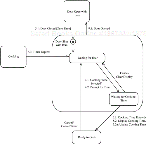
An example of hierarchical state decomposition is given in Figure 8.3, where the Door Shut with Item superstate is decomposed into the Waiting for User and Waiting for Cooking Time substates. (On the hierarchical statechart, the superstate is the outer rounded box, which contains the name of the superstate at the top left. The substates are shown as inner rounded boxes.) When the system is in the Door Shut with Item superstate, it is in one (and only one) of the substates. Because the states are executed sequentially, this kind of hierarchical state decomposition is referred to as resulting in a sequential statechart.
Figure 8.3. Hierarchical statechart for Microwave Oven Control (kernel functionality): decomposition of the Door Shut with Item state
Note that each transition into the superstate is a transition into one (and only one) of the substates on the lower-level statechart. Each transition out of the superstate has to originate from one (and only one) of the substates on the lower-level statechart.
The hierarchical statechart notation also allows a transition out of every one of the substates on a statechart to be aggregated into a transition out of the superstate. Careful use of this feature can significantly reduce the number of state transitions on a statechart. In Figure 8.3, for example, the Door Opened event may occur in either the Waiting for User or the Waiting for Cooking Time substate, in which case the statechart transitions to the Door Open with Item state. Instead of depicting the Door Opened event as causing a transition out of each substate, it is more concise to show this event causing the transition out of the superstate Door Shut with Item.
The history state is another useful characteristic in hierarchical statecharts. Indicated by an H inside a small circle, a history state is a pseudostate within a sequential superstate, which means that the superstate remembers its previously active substate after it exits. Thus, when the superstate is reentered, the previously active substate is entered.
Consider how the history state is used within the Door Shut with Item superstate shown in Figure 8.3. The history state is used to remember which of the two substates the superstate Door Shut with Item is in when an event transitions the statechart out of the superstate. Thus the previous substate is reentered when the Door Shut with Item superstate is reentered. For example, if the superstate is in the Waiting for User substate when the door is opened, the statechart will transition to Door Open with Item. When the door is closed (and assuming zero time), the Door Shut with Item superstate is reentered, and in particular the Waiting for User substate is reentered. On the other hand, if the superstate is in the Waiting for Cooking Time substate when the door is opened, then that substate is reentered when the door is closed. Without the history state, this behavior would be much more difficult to model.
Another kind of hierarchical state decomposition is concurrent state decomposition. That is, a state on one statechart can be decomposed into two or more concurrent statecharts. The two concurrent statecharts are shown separated by a dashed line. Consider the case of a superstate on a statechart that is decomposed into two lower-level concurrent statecharts. When the higher-level statechart is in the superstate, it is simultaneously in one of the substates on the first lower-level concurrent statechart and in one of the substates on the second lower-level concurrent statechart.
The most effective use of a concurrent statechart is for modeling the orthogonal aspects of the same object. Although the name concurrent statechart implies that there is concurrent activity within the object containing the statechart, this kind of decomposition can also be used to show different aspects of the same object that are not concurrent. Designing objects with only one thread of control is much simpler and is strongly recommended. Where true concurrency is required, use multiple concurrent objects and define each object with its own statechart, as described in more detail in Section 8.9.
The term orthogonal statechart describes a concurrent statechart used to depict the states of different aspects of an object. An example of using orthogonal statecharts to depict guard conditions is given in Figure 8.4 for the microwave oven statechart. The Microwave Oven Control statechart is now decomposed into two orthogonal statecharts: one for sequencing the events and actions in the oven (Microwave Oven Sequencing), and the other for Cooking Time Condition. The two statecharts are depicted on a high-level statechart, with a dashed line separating them.
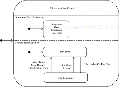
Note: Microwave Oven Sequencing superstate is decomposed into Microwave Oven Control Statechart in Figure 8.1.
Figure 8.4. Orthogonal statecharts for Microwave Oven Control
At any one time, the Microwave Oven Control superstate is in one of the substates of the Microwave Oven Sequencing statechart and one of the substates of the Cooking Time Condition statechart. Cooking Time Condition is a simple statechart consisting of two states—Zero Time and Time Remaining—with Zero Time as the initial state. The Update Cooking Time event causes a transition from Zero Time to Time Remaining. Either the Timer Expired event or the Cancel Timer event can cause a transition back to Zero Time. The Microwave Oven Sequencing statechart depicts the sequence of states the oven goes through while handling a user request to cook food, as shown in Figure 8.1. The Microwave Oven Control statechart is the union of the Microwave Oven Sequencing and the Cooking Time Condition statecharts.
The Zero Time and Time Remaining states of the Cooking Time Condition statechart (see Figure 8.4) are the guard conditions checked on the Microwave Oven Sequencing statechart when the Door Closed event is received while in the Door Open with Item state (see Figure 8.1). Cancel Timer is an action (cause) on the Microwave Oven Sequencing statechart and an event (effect) on the Cooking Time Condition statechart, which causes a transition to the Zero Time state. Update Cooking Time is also an action on the former statechart and an event on the latter. Timer Expired is an event on both statecharts.
State-dependent control classes are depicted by means of statecharts. Because there can be product line variants of a control class, each variant can be modeled with its own statechart. If the variants are all mutually exclusive, then the statecharts are also mutually exclusive, because they model alternative variants. For example, a given microwave oven system can come with or without a recipe feature. The product line would need to have (at least) two mutually exclusive variants of the Microwave Oven Control class, each with its own different statechart. The recipe version of the statechart would need to have additional states and transitions to handle cooking food with a recipe.
However, it is possible in some applications for the variant features to coexist in the same system; that is, they are not mutually exclusive. Consider an elevator control system with multiple elevators, only some of which have a high-speed feature for bypassing the first 20 floors. This case would again be represented by two different features, where each type of elevator is modeled with a different statechart. Because the two elevators can coexist in the same system, however, it is possible to select both features (for different elevators) and hence to have coexisting variant statecharts.
There are two choices for modeling variants of a software product line. Each variant can be modeled with its own finite state machine. This approach has the advantage of encapsulating each change in a separate class, hence encouraging the separation of concerns. If there are potentially many variants and combinations of variants, however, configuration management becomes a major problem—in particular, keeping track of the variants. In addition, if statechart variability is introduced through inheritance, a change in a superclass could have an impact on all its subclasses. An alternative is to use parameterized statecharts and feature conditions, which act as guards preventing a branch of the statechart to be entered if the feature has not been selected. The two approaches for managing state machine variability in product lines—inheritance and parameterization—are described and compared next. Section 8.4 describes inherited state machines in software product lines, and Section 8.5 describes parameterized state machines in software product lines. The two approaches are compared in Section 8.6.
Inheritance is one of the two main approaches of introducing state machine variability into software product lines. When a state machine is specialized, the child state machine inherits the properties of the parent state machine; that is, it inherits the states, events, transitions, actions, and activities depicted in the parent state machine model. The child state machine can then modify the inherited state machine as follows:
Add new states. The new states can be at the same level of the statechart hierarchy as the inherited states. Furthermore, new substates can be defined for either the new or the inherited states. In other words, a state in the parent state machine can be decomposed further in the child state machine. It is also possible to add new orthogonal states—that is, new states that execute concurrently with the inherited states.
Add new events and transitions. These events cause new transitions to new or inherited states.
Add or remove actions and activities. New actions can be defined that are executed on transitions into and out of new or inherited states. Exit and entry actions, as well as new activities, can be defined for new or inherited states. It is also possible to remove predefined actions and activities, although this should be done with care and is generally not recommended.
The child state machine must not delete states or events defined in the parent. It must not change any superstate/substate dependency defined in the parent state machine.
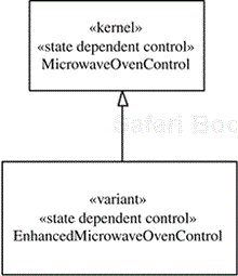
As an example of an inherited state machine, consider the Microwave Oven Control class from the microwave oven software product line, which specifies the state machine of the same name. The Microwave Oven Control kernel state machine, which captures the kernel functionality of the product line, is depicted in Figures 8.1, 8.3, and 8.4. The Microwave Oven Control state machine is then specialized to provide the additional features for the Enhanced Microwave Oven Control child state machine. The specialization of the Microwave Oven Control state-dependent control superclass to produce the Enhanced Microwave Oven Control subclass is depicted in the class diagram of Figure 8.5.
The statechart for the Enhanced Microwave Oven Control class is shown in Figures 8.6 and 8.7. Only parts of the solution are given in this chapter; for the full solution, refer to Chapter 13. Consider the impact of the following features incorporated into the specialized state machine:
Power LevelRecipeTOD ClockTurntableLightBeeperMinute PlusExample of new states added (see Figure 8.7). To support the
Power Levelfeature, a new state is introduced calledWaiting for User after Power Level. To support theRecipefeature, a new superstate is introduced calledRecipe(see Figure 8.6), which has three recipe-related substates (see Chapter 13). To support theTOD(time-of-day)Clockfeature, the inheritedDoor Shutstate is specialized to create three new substates (see Chapter 13).Example of new transitions added (see Figure 8.7). To support the
Power Levelfeature, a new transition is introduced into the newWaiting for User after Power Levelstate, which is triggered by the new eventPower Level Selected. To support theRecipefeature, several new transitions are introduced, including theRecipe Enteredevent, which transitions the statechart into theRecipesuperstate (see Chapter 13).Example of new actions added (see Figure 8.6). There are several examples. To support the
Turntablefeature, two new actions are provided:Start Turning(which is executed on entry into the inheritedCookingstate) andStop Turning(which is executed on exit from theCookingstate). To support theLightfeature, two new actions are provided: theSwitch Onentry action and theSwitch Offtransition action. To support theBeeperfeature, theBeepaction is added, which is also executed on exit from the inheritedCookingstate.
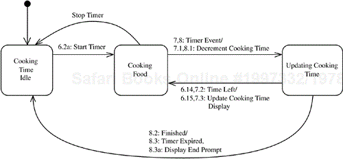
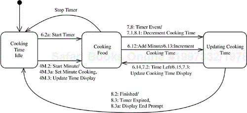
As a second example, consider the Oven Timer state machine. The kernel Oven Timer (Figure 8.8) has three states: Cooking Time Idle, Cooking Food, and Updating Cooking Time. Oven Timer & Minute Plus is a variant state machine that supports the Minute Plus optional feature (Figure 8.9). It inherits the Oven Timer state machine and adds two new transitions to address two new events when the Minute Plus key is pressed: Start Minute and Add Minute. Another inherited state machine is Oven & Recipe Timer (Figure 8.10), which also inherits from the kernel Oven Timer statechart and adds an orthogonal state machine for Recipe Timer, which consists of four sequential states: Recipe Idle, Cooking with Recipe, Updating Recipe Time, and Ending Recipe Step (see Chapter 13).
Although this approach works quite well when the effects of individual features are considered, feature interactions become a major problem when combinations of features are considered. Each feature combination could require a new state machine. Consider the state machine for Oven & Recipe Timer & Minute Plus, which combines the Recipe and Minute Plus features. This is an example of feature interaction because the two previous state machines—the Oven & Recipe Timer statechart and the Oven Timer & Minute Plus statechart—have to be replaced by one state machine that combines the effects of the Minute Plus and Recipe features. Oven & Recipe Timer & Minute Plus inherits from Oven Timer, and then one orthogonal state machine is added for Recipe Timer (see Figure 8.10), as well as two new transitions for Minute Plus (see Figure 8.9). Note that Cooking Timer Superstate on Figure 8.10 is decomposed into the three substates on Figure 8.9.
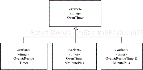
There is a state-dependent control class for each of these statecharts. The generalization/specialization hierarchy for these classes is depicted in Figure 8.11, which shows that the kernel Oven Timer state-dependent control class is specialized into the Oven & Recipe Timer, Oven Timer & Minute Plus, and Oven & Recipe Timer & Minute Plus state-dependent control classes. The combinatorial problem is exacerbated if one more feature is added, affecting the statechart as described further in Section 8.6.
An alternative approach to inheritance for introducing state machine variability into software product lines is to use parameterization and parameterized state machines. With this approach, there is one parameterized state machine and one state-dependent control class, which contains the state machine. This state machine should be designed with all the states, transitions, events, actions, and activities corresponding to all the features. The state machine is tailored to the needs of an individual system by the setting of appropriate values for the parameters. In particular, parameters are used for feature conditions, as described next.
Each feature that affects a state machine is given a Boolean guard condition, which is called a feature condition and depicted in square brackets: [feature condition]. If the feature condition is true, then the feature is selected; if the feature condition is false, then the feature is not selected. In the case of several alternatives of which only one feature must be selected, only one of the alternatives must be true; all the others must be false. Feature conditions are used as guard conditions on the new state transitions that are introduced because of the optional and alternative features. For a state transition to take place, the event must arrive and the feature guard condition must be true, meaning that the feature is provided. If a feature results in a sequence of new states and transitions, then only the transition into the first state in the sequence needs to have a guard condition, because the subsequent states can be reached only if the first state is entered. The values of the feature conditions are set either at system configuration or at runtime initialization of the application, and subsequently they remain unchanged for the duration of the application. Note that, by convention, the first letter of a feature condition is lowercase to distinguish it from other types of guard conditions.
Consider the Enhanced Microwave Oven Control state machine, which incorporates all the features of the microwave oven. For the Power Level feature (Figure 8.13), the feature condition [power] is defined, which is used to guard the transition Power Level Selected [power]. Thus this transition can be taken only if the feature is selected, in which case the feature condition [power] is true. The same approach is used for the Recipe feature which has a transition Recipe Entered [recipe], guarded by the [recipe] feature condition (Figure 8.12).
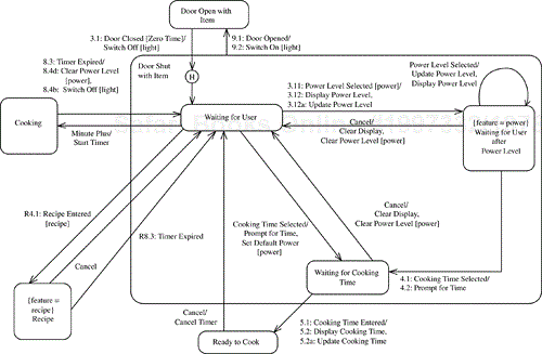
Figure 8.13. Parameterized statechart for Microwave Oven Control (with all features): decomposition of the Door Shut with Item state
It is also possible to have feature-dependent actions and activities. If a state transition that occurs has an action or activity guarded by a feature condition, then the action or activity is feature-dependent and will execute only if the feature condition is true.
To support the Turntable feature, two new actions are provided: Start Turning (which is executed on entry into the inherited Cooking state) and Stop Turning (which is executed on exit from the Cooking state) (see Figure 8.12). Both actions are given the feature guard condition [turn] to indicate that their execution is conditional on the condition being true. To support the Light feature, two new actions are provided—Switch On and Switch Off—which are guarded by the feature condition [light]. To support the Beeper feature, the Beep action is added, which is also executed on exit from the inherited Cooking state and is guarded by the feature condition [beeper]. If the transition is taken, the action is executed only if the feature condition is true.
Finally, a state that is dependent on a feature for its existence is referred to as a feature-dependent state and is identified by a UML constraint. For example, the notation {feature = recipe} Recipe is used to indicate that the Recipe superstate is provided only if the Recipe feature has been selected (see Figure 8.12).
As described in Sections 8.4 and 8.5, there are two different approaches to providing software product line variability for state-dependent control classes: One is to design inherited state machines, and the other is to design parameterized state machines. This section compares the two approaches.
Consider the approach of designing an inherited state machine for each variation. The main advantage of this approach is that it isolates each variation in one variant state machine model. It is also means that each variant state machine is affected by only one feature or feature combination. However, the main disadvantage of this approach is that a large number of variations can lead to a combinatorial explosion of variant state machines. One approach to help manage this problem is to reduce the number of combinations by permitting only certain prespecified packaged feature and variant combinations, as illustrated in Section 8.6.
An alternative approach to designing inherited state machines is to design one parameterized state machine that captures the states, events, transitions, actions, and activities needed by all the different features. The main advantage of this approach is that there is only one parameterized state machine instead of many variant state machines, so the configuration management problem is simplified. Furthermore, the addition of a new state-dependent feature affects only one state machine instead of several. The main disadvantage is that a parameterized state machine is affected by more than one feature.
Although it is possible to use a combination of inherited and parameterized state machines in order to take advantage of both approaches, the recommendation is to use only inherited state machines if there are a small number of variants. If there are many state-dependent features, as in the Microwave Oven Control example, the parameterized state machine approach is strongly recommended.
Now consider some examples of both inherited and parameterized state machines from the microwave oven product line. Consider the features that affect the Microwave Oven Control state-dependent control class. These include Power Level, Recipe, TOD Clock, Minute Plus, Light, Turntable, and Beeper. If an inherited state machine were designed for each feature and feature combination, the result would be a large number of possible combinations. Each feature and feature combination would need its own inherited state machine and subclass. With a parameterized state machine, there would be only one parameterized state machine and class, so parameterization is the preferred approach.
Consider another example from the microwave oven product line—namely, Oven Timer. Two features affect this state machine: Recipe and Minute Plus. The result is four variants, as described in Section 8.4. However, consider the impact of another feature, Delayed Timer. Even with this small number of variations, the effects of the combinatorial explosion are obvious. Designing an inherited state machine for each feature and feature combination would result in eight variants to support each of the possible combinations: Timer, Timer & Minute Plus, Timer & Delayed Timer, Timer & Recipe, Timer & Minute Plus & Delayed Timer, Timer & Minute Plus & Recipe, Timer & Delayed Timer & Recipe, and Timer & Minute Plus & Delayed Timer & Recipe. It is possible to reduce the number of combinations by restricting the number of combinations—for example, by specifying beforehand certain permitted packaged feature combinations for the product line. For example, the number of variants could be reduced from eight to four if the following kernel plus three feature combinations were chosen: Timer, Timer & Minute Plus, Timer & Minute Plus & Recipe, Timer & Minute Plus & Recipe & Delayed Timer.
Because of the potential combinatorial explosion with inheritance, parameterization is the preferred approach and is used in the statecharts for the microwave oven product line case study in Chapter 13.
During object structuring, the objects that participate in the realization of a use case are determined. If at least one of the objects is a state-dependent control object, then the interaction is defined as state-dependent. State-dependent dynamic analysis is a strategy to help determine how objects interact with each other in state-dependent interactions. A state-dependent interaction involves at least one state-dependent control object, which executes a statechart that provides the overall control and sequencing of the interactions. In more-complex interactions, it is possible to have more than one state-dependent control object. Each state-dependent control object is defined by a statechart.
With the kernel first approach, state-dependent dynamic analysis for the kernel system is similar to dynamic analysis for a single system. This is followed with the software product line evolution approach, which analyzes the impact of each feature on the kernel statechart(s) and kernel object interactions.
In state-dependent dynamic analysis, the objective is to determine the interactions among the following objects:
The state-dependent control object, which executes the statechart
The objects, usually interface objects, that send the events to the control object that cause the state transitions
The objects that provide the actions and activities, which are triggered by the control object as a result of the state transitions
Any other objects that participate in the use case
The interaction among these objects is depicted on a communication diagram or sequence diagram.
The main steps in the state-dependent dynamic analysis strategy are as follows:
Determine the interface object(s). Consider the objects that receive the inputs sent by the actor.
Determine the state-dependent control object. There is at least one control object, which executes the statechart. Others might also be required.
Determine the other internal objects. These are internal objects that interact with the control object or interface objects.
Determine object interactions. Carry out this step in conjunction with step 5 because the interaction between the state-dependent control object and the statechart it executes needs to be determined in detail.
Determine the execution of the statechart. See Section 8.7.2.
Consider alternative sequences. Perform the state-dependent dynamic analysis on the alternative sequences of the use case.
This section describes how interaction diagrams—in particular, communication diagrams and statecharts—can be used together to model state-dependent interaction scenarios.
A message on an interaction diagram consists of an event and the data that accompanies the event. Consider the relationship between messages and events in the case of a state-dependent control object that executes a statechart. When a message arrives at the control object on a communication diagram, the event part of the message causes the state transition on the statechart. The action on the statechart is the result of the state transition and corresponds to the output event depicted on the communication diagram. In general, a message on an interaction diagram (communication or sequence diagram) is referred to as an event on a statechart; in descriptions of state-dependent dynamic scenarios, however, for conciseness only the term event is used.
A source object sends an event to the state-dependent control object. The arrival of this input event causes a state transition on the statechart. The effect of the state transition is one or more output events. The state-dependent control object sends each output event to a destination object. An output event is depicted on the statechart as an action (which can be a state transition action, an entry action, or an exit action), an enable activity, or a disable activity.
The statechart needs to be considered in conjunction with the communication diagram. In particular, it is necessary to consider the messages that are received and sent by the control object, which executes the statechart. An input event into the control object on the communication diagram must be consistent with the same event depicted on the statechart. The output event (which causes an action, enables an activity, or disables an activity) on the statechart must be consistent with the output event shown on the communication diagram.
To ensure that the communication diagram and statechart are consistent with each other, the equivalent communication diagram message and statechart event must be given the same name. Furthermore, for a given state-dependent scenario it is necessary to use the same message numbering sequence on both diagrams. Using the same sequence ensures that the scenario is represented accurately on both diagrams and can be reviewed for consistency. These issues will be illustrated in the following example.
As an example of the kernel first approach to state-dependent dynamic modeling, consider the kernel communication diagram for the Cook Food use case. Several objects support this use case, as depicted in Figure 8.14. The state-dependent control object, Microwave Oven Control, executes the Microwave Oven Control statechart and thereby controls the execution of several objects. To fully understand and design the state-dependent interactions, it is necessary to analyze how the communication diagram and statechart work together. A message on the communication diagram and its equivalent event on the statechart are given the same name and sequence number to emphasize how the diagrams work together.
Consider one event sequence initiated by an external object—namely, Keypad. At the start of this scenario, the statechart is in the Ready to Cook state (see Figure 8.1). When the user presses the Start key, the external Keypad object sends the Start Key Input message (message 6 on Figure 8.14) to the software Keypad Interface object, which in turn sends a Start message (message 6.1) to the Microwave Oven Control object. The arrival of the message triggers the Start event on the Microwave Oven Control statechart (event 6.1 on Figure 8.1), which in turn causes the state transition from the Ready to Cook state to the Cooking state. The resulting actions are the transition action Start Timer and the entry action Start Cooking. The effect of the Start Timer action (event 6.2a on Figure 8.1) is that the Microwave Oven Control object sends the Start Timer message (message 6.2a on Figure 8.14) to the Oven Timer object. The arrival of this event at Oven Timer triggers a state transition from Cooking Time Idle to Cooking Food (event 6.2a on Figure 8.8). The effect of the Start Cooking action (event 6.2 on Figure 8.1) is that the Microwave Oven Control object sends the Start Cooking message (message 6.2 on Figure 8.14) to the One-level Heating Element Interface object, which then sends Start Cooking Output (message 6.3) to the external One-level Heating Element object. Switching on this actuator physically initiates the cooking.
When the timer counts down to zero, the Oven Timer object sends the Timer Expired message (event 8.3 on Figures 8.1, 8.8, and 8.14) to Microwave Oven Control, resulting in the transition to Door Shut with Item and the execution of the exit action Stop Cooking. The effect of the Stop Cooking action (event 8.4 on Figures 8.1 and 8.14) is that the Microwave Oven Control object sends the Stop Cooking message to the One-level Heating Element Interface object, which then sends Stop Cooking Output to the external One-level Heating Element object. Switching off this actuator physically stops the cooking.
To model state-dependent variability with the software product line evolution approach, start with kernel state-dependent communication diagrams developed with the kernel first approach, and then consider the impact of those features that affect the state-dependent control object and statechart. On the statechart, this analysis is likely to result in new states and new transitions, requiring new events and actions or activities. On the communication diagram, the analysis is likely to result in additional objects, which are then categorized as optional or alternative objects, which replace objects in the kernel system, as well as additional messages.
Consider the impact of adding optional features to the kernel system for the microwave oven product line. As an example, consider the Light, Turntable, and Beeper optional features; each feature needs an optional output device interface object added, as well as state-dependent actions to control it. The new objects are Lamp Interface, Turntable Interface, and Beeper Interface, which in turn communicate with the external output device objects Lamp, Turntable, and Beeper, respectively. However, these features also affect the state-dependent control object, Microwave Oven Control, because this object has to trigger the actions that control the output device interface objects. Thus the actions have to be added to the statechart for Microwave Oven Control, as shown in Figure 8.12.
For example, the Turntable feature affects the Cooking state, which needs the entry action Start Turning (action 6.2c on Figure 8.12) on entering the state and the exit action Stop Turning (action 8.4c) on leaving the state. The Beeper feature requires the exit action Beep (action 8.4a) on leaving the state. For the Light feature, other transitions are affected as the light is switched on (such as actions 1.2 and 9.2) whenever the door is opened and switched off when the door is closed (such as action 3.2). Thus the Light feature necessitates the additional transition actions Switch On and Switch Off.
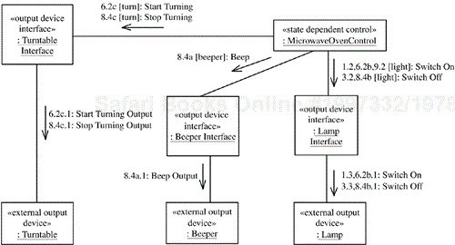
The impact of these three features on the Cook Food communication diagram is shown in Figure 8.15, which shows only the affected and new objects compared to Figure 8.14. Microwave Oven Control is affected by the new features and sends messages—which correspond to the new statechart actions—to the new objects as follows:
Start Turning(message 6.2c) andStop Turning(message 8.4c)— which correspond to the actions with the same names on the statechart— toTurntable Interface, the output device interface objectSwitch On(messages 1.2, 6.2b, 9.2) andSwitch Off(messages 3.2, 8.4b)—which correspond to the actions with the same names on the statechart—toLamp InterfaceBeep(message 8.4a)—which corresponds to the action with the same name on the statechart—toBeeper Interface
Other features result in the design of new transitions. An example is the Minute Plus feature, which has a state-dependent impact. Minute Plus can be pressed either when the oven is in the state Door Shut with Item (see Figure 8.12), in which case the Cooking state is entered, or during the Cooking state, in which case the state does not change but the cooking time is incremented.
Other features (e.g., Recipe) result in the design of new states. In fact, the impact of the Recipe feature is to add a Recipe superstate (see Figure 8.12), which is decomposed into the substates Ready to Cook with Recipe, Door Open with Recipe, and Cooking with Recipe. The transitions between these states also need to be defined. This is described in more detail in Chapter 13.
This section describes how scenarios involving communicating state-dependent control objects are developed. Each state-dependent control object executes a finite state machine, which is depicted as a statechart. If the finite state machines need to communicate with each other, they do so indirectly. The objects that contain these state machines send messages to each other as described in this section.
Consider the following. As a result of transitioning from one state to another, the action of a finite state machine is to send a message. This message is actually sent by the object that executes the finite state machine, referred to as the source object. A destination object receives the message. The message causes a state transition in the finite state machine executed by the destination object. Thus the action of a source finite state machine causes a state change on a destination finite state machine.
An example can be extracted from the factory automation product line case study, which is described in detail in Chapter 15. Three instances of the Line Workstation Controller class communicate with each other. These three objects—predecessor Line Workstation Controller, a Line Workstation Controller, and successor Line Workstation Controller—are connected in series as depicted on the communication diagram in Figure 8.16. The factory uses a just-in-time algorithm, which is fully explained in Chapter 15. Briefly, a workstation sends a physical part to the next workstation in sequence (its successor) after it receives a Part Request message from the successor. After sending the part, the workstation sends a Part Coming message to its successor and a Part Request message to its predecessor, as depicted in Figure 8.16. Each Line Workstation Controller object executes a statechart. The statecharts are identical, but the objects are usually in different states on their statecharts. The instances of the statecharts for the three objects are depicted in Figures 8.17, 8.18, and 8.19.

Figure 8.16. Communicating state-dependent control objects: communication diagram for three instances of Line Workstation Controller
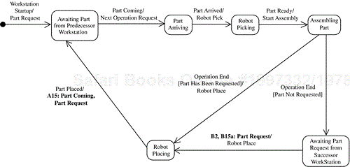
Figure 8.17. Communicating state-dependent control objects: statechart for Predecessor Line Workstation Controller

Figure 8.18. Communicating state-dependent control objects: statechart for a Line Workstation Controller

Figure 8.19. Communicating state-dependent control objects: statechart for Successor Line Workstation Controller
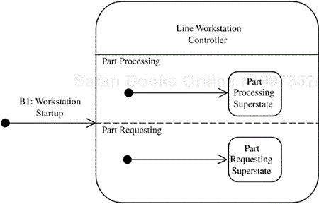
The high-level statechart for each Line Workstation Controller is depicted in Figure 8.20 and consists of two orthogonal superstates: Part Processing Superstate (which is decomposed into the sequential statecharts shown in Figures 8.17 through 8.19) and Part Requesting Superstate (which is decomposed into the sequential statechart shown in Figure 8.21). The latter statechart has two substates, Part Not Requested and Part Has Been Requested. These two substates correspond to the guard conditions with the same names on the Part Processing statecharts, as depicted in Figures 8.17 through 8.19.
Consider the communication diagram in Figure 8.16 and the statechart for a Line Workstation Controller shown in Figure 8.18. Figure 8.18 shows that when this object transitions from the Robot Placing state to Awaiting Part from Predecessor Workstation, the transition triggers two actions: Part Coming (B15) and Part Request (B15a). These actions result in corresponding messages being sent to the neighbor workstations. Figure 8.16 shows that the Part Request message is sent to the predecessor Line Workstation Controller object, causing it to transition from the Awaiting Part Request from Successor Workstation state to the Robot Placing state (see Figure 8.17). Figure 8.16 also shows that the Part Coming message is sent to the successor Line Workstation Controller object, causing it to transition from the Awaiting Part from Predecessor Workstation state to the Part Arriving state (see Figure 8.19). The reason that some messages have two sequence numbers—for example, A15 and B3 for Part Coming on Figure 8.16—is that the same message occurs at different places in the message sequencing scenarios for the sender (A15) and receiver (B3) objects.
This chapter described how to develop finite state machines and statecharts for software product lines. The most effective use of statecharts in software product lines is for modeling state-dependent control classes and objects, taking advantage of hierarchical statechart decomposition. In particular, each state-dependent control class—whether kernel, optional, or variant—needs to be modeled with a finite state machine and depicted as a statechart. It is also possible to model variations in software product lines using inherited state machines and parameterized state machines; the two approaches were described and compared in this chapter. The integration of statecharts and interaction diagrams—in particular, communication diagrams—during state-dependent object interactions was also described.
Chapter 10 will describe several software architectural control patterns in which finite state machines and state-dependent control objects play an important role. These patterns include the centralized control architectural pattern, the distributed control architectural pattern, and the hierarchical control architectural pattern. Examples of finite state machines, state-dependent control objects, and software architectural control patterns will be given in the case studies in Chapters 13 and 15.

