The First Pass
Screen Structure Charts
In my early days as a developer of client/server applications, I created physical screen layouts immediately during prototyping. All too often, I then found myself in discussions with my business sponsor tackling issues along the lines of, “Move the OK button over 4 pixels” and “Wouldn't a gray background be more appealing?” Discussions like these shouldn't dominate the prototype. Instead, the prototype should initially identify major window groups and the overall strategy for look and feel, and only at the end address issues of aesthetics.
Researchers have found that 60 percent of an application's usability can be traced to how well the user interface maps to the mental model of the user. Some people also refer to this as someone's mind map. Interaction accounts for 30 percent; presentation, for 10 percent. Surprisingly, developers usually first approach the task that has the lowest impact on usability.
In an effort to streamline the prototyping process, we will create screen structure charts before creating any actual screens. A structure chart is a low-technology way to storyboard the application flow, specifically the flow of pathways through the use-cases. The chart consists of various easy-to-use symbols. Figure 6-4 shows an example.
Figure 6-4. Screen structure chart symbols
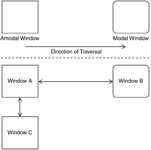
The symbols describe the major types of windowing activities in a graphical application:
Amodal (modeless) window: Does not require a response from the user. For example, the window might be invoked and then minimized or bypassed in favor of another window within the application or another application entirely. Any Microsoft Office application is a good example of an amodal window.
Modal window: Requires a response from the user. For example, the window might be invoked but will require that the user complete the dialog box or cancel out of it. (This statement actually is misleading because if you are a Microsoft Windows user, the Alt+Tab key combination can be used to invoke application toggle functionality on any other open applications.) The Save As dialog box in most applications is a good example of a modal window.
Direction of traversal: Shows the pathway of window navigation. For example, suppose you are in a Java internal-frame setup and a toolbar or menu item allows a transaction-based window to be opened, giving the user the option to return when that window is closed. Then the arrow will display as two-headed from the containing frame to the transaction window.
This low-technology approach can yield high rewards. We can also model some of the more often used controls, such as tabbed controls, as we will do for Remulak Productions. A tabbed control represents a form of logical paging and can be expressed with a focus block for a specific window, as shown in Figure 6-5.
Figure 6-5. Logical paging using focus blocks

The tabbed controls, shown as windows in the figure, are embedded on the physical window, but they actually represent separate navigational elements of the user interface. They also are often mutually exclusive. Sometimes just showing window navigation alone isn't sufficient. In the case of windows, which use tabbed dialogs or in some cases master detail grids, distinguishing them as separate logical entities is important. Although these logical entities generally are layered onto one physical window, in some cases they are really user-driven navigational choices.
We create two structure charts for Remulak Productions in this chapter. Figure 6-6 depicts the overall screen structure chart for the order entry application. Figure 6-7 depicts the screen structure chart to support the Process Orders use-case.
Figure 6-6. Remulak overall screen structure chart

Figure 6-7. Remulak Process Orders screen structure chart

Creating the Prototype
In the early days of Java, the creation of the visual portion for the application was excruciatingly slow and frustrating. The lack of visual development environments often prompted developers to use a different tool to visually prototype the application, perhaps Visual Basic or even Adobe FrameMaker or Microsoft Visio. This situation quickly changed with the introduction of integrated development environments (IDEs) for Java.
My next few comments will surely alienate some readers. This reaction is natural because of the religious nature and personal bias toward various vendors' IDE products. Many of you who learned Java did so in a classroom setting that didn't utilize an IDE. I am a big believer in this approach at the beginning of your Java education because it provides an excellent foundation for understanding the language. After the initial Java training, however, you're making a big mistake if you don't run out and buy an IDE to build your applications. These environments will save you hundreds if not thousands of hours of development time over the course of their usage.
Other very esteemed individuals disagree, including James Gosling, the father of Java, who stated in an interview by SYS-CON Radio at the June 2001 JavaOne conference, “Real programmers don't use IDEs but instead stick with a good editor, since IDEs are too constraining.” On occasion I still run across a development team that abides by this creed. My reply is simply, “Why?” I personally would rather have a root canal than use a line editor to build enterprise Java applications.
There are many IDE products on the market today, but three in particular are continually reviewed and compared together. Over the last several years, I have seen their rankings constantly shift, but they consistently are perceived as best-of-class IDE products. These products are JBuilder (by Inprise, formerly Borland), Visual Age for Java (by IBM), and VisualCafé (by WebGain). Yes, there are others out there, but the three mentioned here capture the lion's share of the Java IDE market.
As Java has evolved, and more recently with the release of the Java 2 Platform, Enterprise Edition (J2EE), the selection of the IDE has become even more contested. Clearly, one of the standouts of this latest release of Java is Enterprise JavaBeans (EJB). However, an effective EJB strategy requires an application server that implements the EJB infrastructure. All three IDE products either offer their own application server product (e.g., Inprise Application Server, IBM WebSphere Application Server) or are closely aligned with an application server provider (e.g., BEA WebLogic's strategic alliance with WebGain's VisualCafé). This isn't to say that you can't, for instance, build EJB applications and then deploy them on a different vendor's application server, but at times the integration is implemented in a more seamless fashion.
Given that bit of history, I intend to utilize Inprise's JBuilder for some of the examples in this book. I won't go into the nuances of the product but will use it to show some of the visual results. The beauty of Java is that all of the code that is available with the book will work in any of the vendor's products mentioned. To keep the playing field equal, and more importantly to provide more value-added information to readers so that they can pick their own tools for coding, I have purposely not used any of the vendor-provided unique classes or components.
Windowing Components
Using the structure chart presented in Figure 6-7, we can lay out some of the screen components. Keep in mind that these screens aren't “art fancy.” They contain virtually no “eye candy.” In practice you would probably want to employ the services of a graphic artist to make the screen designs really stand out. Figure 6-8 displays the Remulak initial Web page, which has no eye-candy.
Figure 6-8. Remulak order portal
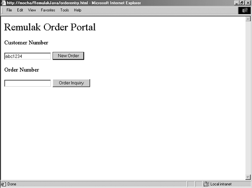
The order portal allows for two branches in the screen dialog. One branch allows for the entry of a new order; the other, for a query on an existing order. Assuming a new order, we have the screen shown in Figure 6-9.
Figure 6-9. Product selection
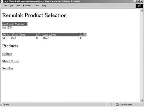
This screen allows the user to select a product category from which products will be chosen. In this case, if the user chooses Guitars as the product category, the screen in Figure 6-10 will pop up.
Figure 6-10. Guitar selection
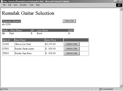
Figure 6-10 shows how a particular product is added to the shopping cart: by selection of the button Add to Cart. Pressing the View Cart button at this point will display the current shopping cart. Let's assume that we also added a sheet music item to our cart. Selecting View Cart would then display Figure 6-11.
Figure 6-11. Viewing the shopping cart
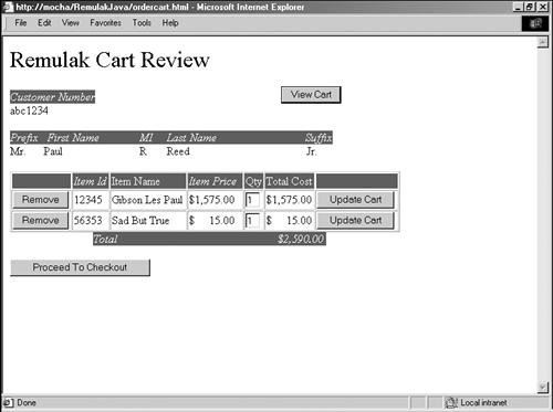
The View Cart screen offers several options. The user can change the Qty field and then press Update Cart. Note that this action does cause another screen to open; the same screen is simply displayed with the updated quantity now confirmed, along with a recalculated price.
The user may also remove any item by pressing the corresponding Remove button. Just as with Update Cart, this action will redisplay the same screen with updated pricing and line items. Assuming that all is well at this point, Figure 6-12 shows the screen that is displayed if Proceed To Checkout is pressed on Figure 6-11.
Figure 6-12. Order review
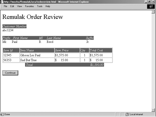
Note that at this stage the screen is the same as the one that is displayed if the user wishes to inquire about an order, as was made possible in Figure 6-8. Users who like what they see may confirm the order by pressing Continue on the screen depicted in Figure 6-12. The order confirmation screen is very basic and is merely meant to give users information, providing them with an order number as shown in Figure 6-13.
Figure 6-13. Order confirmation

Collecting User Feedback by Using Screen Dialogs
User feedback about the screens benefits the prototype. This feedback should cover the following at a minimum:
The logical function that is to be performed
How the function is performed
What happens as a result of the action
These might sound like the events identified in the earlier scoping efforts of the project; however, they concern the screens themselves. To gather this feedback, we follow a low-technology approach, by creating a screen dialog table below a snapshot of each screen image.
It is a good idea also to capture any special edit notes, as well as any special processing information. Table 6-3 shows such a table for the Process Order window, and Figure 6-14 shows the Special Edits/Notes section of the screen dialog for Process Order window.
Figure 6-14. Special Edits/Notes section of screen dialog for Process Order window

The project team members typically perform the screen dialog exercise. It is approached from the user's perspective. Like the use-cases, the screen dialog focuses on the goals to be satisfied.
Learning from the Prototype
The final step is to review the static prototype with Remulak Productions' project sponsors and user team members. Suggestions for improving the user interface, as well as its functionality, always result from this step. If they don't, then either we are doing a very good job or we are dealing with very timid users.
It is important that we incorporate suggested changes, within reason, into the prototype as quickly as possible. This process is called protocycling. We must also separate user interface items from functional scope creep requirements and ensure that they go through some form of change control procedure. Many of the suggested changes are minor screen changes (e.g., to icons or tab ordering) that are easy to change and can be dealt with effectively without change control.
Remulak Productions' user team members have reviewed the screens and completed the screen dialogs, and they like what they see but want a few changes:
No detailed product information on a given product is readily accessible to the order clerk. Although this feature is not considered a showstopper, users think that it would be nice to have this information in case the customer asks for it. In addition, products have associations with other products (i.e., certain guitars are associated with certain brands of strings and other supplies). Users want to be able to retrieve this information, if needed, from the Process Order screen.
Solution: Provide a hyperlink on the item description to allow a more detailed product review.
There is no predefined template order for special orders. Remulak Productions often has special offers that are handled by order clerks who take only those types of orders. Because calls go through a telephone response menu first, these special-offer sales can be routed accordingly. The users want predefined template orders that are retrievable and set as the default according to the order clerk and the clerk's immediate log-on session.
Solution: Allow for a template order dialog box and the ability to associate the template with a user session so that subsequent new orders invoke the previously associated template.
The first item is pretty straightforward. The second item might require a little additional work; it might not be a difficult change, but it is a potentially broad one because it expands the functionality to add additional pathways through three use-cases. Those use-cases and their impact on other UML artifacts are listed in Table 6-4.
The result of the change control process confirms that we should go ahead with the necessary changes in scope and functionality.
This exhaustive example is included because it reflects real life. The changes discussed here represent the types of changes we expect to encounter, and we need to show how the impact analysis might be performed and provide traceability to the UML artifacts that require change.
As an aside, Figures 6-15, 6-16, and 6-17 are screenshots of the Maintain Relationships prototype.
Figure 6-15. Remulak relationship portal
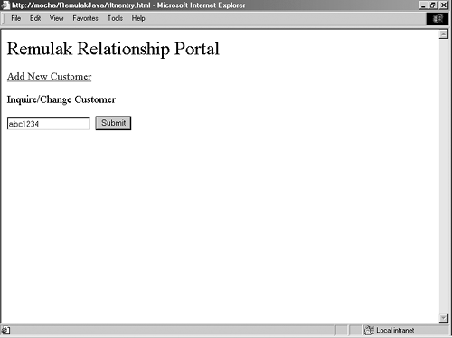
Figure 6-16. Relationship inquiry

Figure 6-17. Relationship maintenance

The beauty of a process model such as the Unified Process, which supports iterative and incremental development, with UML as the artifact trail, is that all of the pieces hang together. The crucial point is that everything is tied back to the use-cases. If something isn't in the use-case, then it won't be in the final deliverable. Changes to use-cases should always go through change control.
We can learn a lot from the user interface prototype. The screen structure chart outlines logical flow (at a high level). The prototype itself gives the unique look-and-feel perspective of the application. And the screen dialog enables the user to offer feedback regarding logical actions, how to perform them, and the results they are expected to produce.
Next let's relate things to the UML deliverables produced thus far. The interaction begins with the actor's interface with the use-case in the form of an initial event that the actor wants to perform—for example, Customer Places Order—which is satisfied by a use-case (from the user's perspective). This ultimately must be realized in a human/machine interface that will assist in satisfying the goal of the use-case. As part of iteratively and incrementally developing applications, this type of feedback mechanism strengthens the final deliverable and builds confidence in the project team's ability to move forward.
