
Chapter 4: HFT System Foundations – From Hardware to OS
In the previous chapter, we learned how an exchange works. We reviewed the functional components of an exchange and the matching engine. This chapter will explain the basic hardware and operating system (OS) of an HFT system.
This chapter will cover the following topics:
- Understanding HFT computers
- Using the OS for HFT
- The role of compilers
We will learn in later chapters that high frequency is relative to the types of trading strategies and the assets you're trading, as well as the capabilities of the exchanges you're trading on. Achieving a tick-to-trade latency of 100 microseconds requires careful programming and a good understanding of the underlying hardware. You need to write code best to take advantage of the CPU and its memory architecture and minimize the overhead of I/O operations. This chapter focuses on getting the baseline (in terms of the hardware and OS that we should have) in order to have an automated trading system that will achieve good performance. Later chapters will help us refine this, applying different optimization techniques to improve latencies in the trading system, getting us down to even below 10-microsecond latencies.
Suppose you want to get an in-depth explanation of how a modern computer system architecture works. In that case, the classic book Computer Architecture: A Quantitative Approach by John Hennessy and David Patterson explains that in detail and develops statistical models to help understand performance trade-offs. In this chapter, we will focus on the pieces that an HFT system needs to function. The following section will introduce the hardware of the machines used by such a system.
Understanding HFT computers
It's easy to imagine you might need some specialized computer hardware for any low-latency trading strategy. This is not the case – most hardware is normal off-the-shelf hardware. How you configure the hardware is more important for most cases. Figure 4.1 shows a primary CPU, representing how a developer of an HFT system thinks about the CPU's architecture.
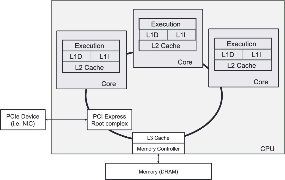
Figure 4.1 – Primary CPU
As we discussed in previous chapters, the purpose of a server in an HFT system is to handle baseline trading functions: receiving market data, executing algorithmic models, and sending orders to an exchange. This system has a network interface to send and receive data to and from a business or communicate with other trading systems inside the firm. Chapter 5, Networking in Motion, focuses on this aspect. Once a packet comes off the wire, the central processing unit (CPU) does the heaviest lifting. Packets will arrive in host memory from the network interface; then, the CPU will pull pieces of the packets into caches so that the CPU execution cores can decode and act on the contents of the packets.
To achieve low latency, you need to consider how your software executes in the CPU and how data flows from the various hardware components to be processed by your trading system and algorithms. In the following sections, we will look at how a CPU works and some CPU microarchitecture details that impact the performance of your software.
CPUs, from multi-processor to multi-core
A CPU is a collection of one or more processor cores that fetch and execute program instructions. These instructions can act on data stored in memory or interface with a connected device. These devices, often called input/output (I/O) devices, connect to the CPU over some expansion bus, such as PCI Express (PCIe). In the past, you needed to have multiple physical chips in a single computer to achieve multi-processing. Over the past decade, to deal with the scaling limits imposed by Moore's law, most CPUs shipped have multiple cores on a single silicon die. As silicon features (such as transistors) have become smaller, yield (the number of fully functional chips) during manufacturing has become a concern, and so there is a move back toward multiple chips (sometimes called chiplets) in a single package.
The CPU core is very good at performing many small logical operations. For example, the CPU can perform basic arithmetic operations (add, subtract, multiply, and divide) and logical operations (AND, OR, NOT, XOR, and bit shifting). More specialized operations, such as CRC32, steps of the Advanced Encryption Standard (AES) algorithm, and a carry-less multiplication (for example, PCLMUQDQ), are also implemented directly by some CPU cores. The CPU can also act on information loaded from memory or read from an input device. The CPU can also change its execution path based on the information it has calculated or read elsewhere. These control flow instructions are the building blocks for high-level language constructs, such as conditional statements or loops.
When market data arrives on a network interface, the CPU handles it. This means parsing the data sent over the network, managing this market data across the different functional parts of the trading systems, and possibly sending an order triggered by this market data to the exchange. In Chapter 2, The Critical Components of a Trading System, we described the essential elements. We discussed that the gateways, order book, and trading strategies were all components working together to trigger an order. With a single CPU execution core, each of these actions would have to happen in sequence, meaning only a single packet could be processed at one time. This means that packets could queue up and wait for the previous packet to finish being processed; this increases the time a message could wait before the trading system can provide this new data to a trading strategy. To reduce latency, we want many processing units working in parallel, handing off the processed market data as quickly as possible to move on to the following message that has arrived. Parallel computing systems have been around since the dawn of computing, though these were used in highly specialized scientific computing applications in the early days. In the 1990s, multi-socket servers became prevalent with two or more CPUs on the same board. Since single-CPU cores could not scale in performance due to Moore's law's limitations, CPU vendors started to add multiple processing cores on a single chip. A modern server can have multiple CPU sockets, each with multiple CPU cores present, achieving a considerable amount of parallelism in a single machine.
Figure 4.2 depicts a modern multi-socket system architecture. Memory or I/O devices are attached directly to a particular CPU socket. These are referred to as being local to the CPU. Other CPUs can be connected in a single system using an interconnect, such as Intel's Ultra Path Interconnect or AMD's Infinity Fabric. Suppose one CPU attempts to access memory or an I/O device attached to a different CPU. In that case, this is referred to as accessing a remote resource. When we compare the time it takes for one CPU to access its local resources with that of a remote CPU over an interconnect, we find that the interconnect is much slower than just accessing local memory. We call this access time non-uniform and call these architectures non-uniform memory access (NUMA). The term cache-coherent NUMA or ccNUMA refers to the fact that a CPU core is guaranteed to have the correct view of memory even if another CPU core has modified the data. NUMA architectures can scale to large numbers of cores. It's possible to think of each CPU as being a separate computer system, all interconnected with each other over a fabric.

Figure 4.2 – A four-way NUMA architecture. Note how the CPUs form a fully connected graph in this configuration
Figure 4,2 also represents a few more components. PCIe is a bus connecting other devices, such as the Network Interface Card (NIC). When there is more than one CPU present in a NUMA architecture, additional CPUs are capable of sharing data by requesting it over the interconnect bus.
A note about hyper-threading and simultaneous multithreading
Simultaneous multithreading, known on Intel CPUs as hyper-threading, is a trick where the CPU keeps track of multiple parallel execution states (two such states, in the case of hyper-threading). When one execution state needs to wait for a high-latency event (such as fetching data from a higher-level cache or RAM), the CPU switches over to the other execution state while waiting for the fetch to complete; this is a kind of automatic threading that is managed by the CPU itself and makes each physical core appear as multiple virtual cores.
There is a temptation to double the number of physical cores using hyper-threading, but this introduces hard-to-control latency that looks like a context switch.
Figure 4.3 depicts the use of hyper-threading in one hyperthreaded core. We can observe that the hardware can fake a concurrent execution if a task needs to wait to access a memory segment while running another one simultaneously. If a system call (or an interruption) demands access to the Kernel, all the tasks will be on hold.

Figure 4.3 – Hyper-threading
The major problem of hyper-threading is that it removes the control of task switching (at the software level), which can create higher jitter and higher latency.
Main memory or RAM
Often called Random Access Memory (RAM), main memory is a large, non-persistent store for program instructions and data. RAM is the first stop for any data read from an I/O device, such as a network card or a storage device. Modern RAM can return data bursts at high throughput but at the expense of latency when data at an address is requested and the data becomes available.
In a typical NUMA architecture, each CPU has some local RAM. Many configurations will have an equal amount of RAM connected to each NUMA node, but this is not a firm requirement. The latency of access to RAM, especially on a remote NUMA node, can be pretty high. So, we need other ways to hide this latency or buffer data, close to the CPU executing some code. This is where caches come into play.
Caches
Modern processors, with many cores, have caches local to each core and caches shared by all cores on a single socket. These caches are designed to take advantage of the fact that programs typically operate on data in the same memory region within a particular time window. This spatial and temporal locality of data access presents an opportunity for the CPU to hide the latency of access to RAM.
Figure 4.4 shows a typical cache hierarchy for a modern multi-core CPU. The L1 cache is split into two parts: a data cache and an instruction cache. The L2 and L3 caches will mix instructions and data freely, as does the main memory.

We will now talk about the structure of the caching system.
Cache structure
Rather than reading a single word or byte from the main memory at a time, each cache entry typically stores a particular number of words, referred to as a cache line. The entire line is read and cached at the same time. When a cache line is read in, another line needs to be evicted to make room for the new cache line. Which line is evicted is often determined on a least-recently-used basis, but other schemes exist. Different levels of cache have different cache line sizes – this is a property of the CPU design itself. There are a variety of details on how to align data structures to cache line sizes to increase the odds of a cache hit, mainly when many related data structures are accessed.
L1 cache
The L1 cache (Level 1) is the quickest memory available in a computer system and it is placed close to the execution units of the CPU. The L1 cache has the data that the CPU has most recently accessed and loaded into registers. The CPU vendor determines the L1 cache size.
The L1 cache is divided into the data cache and the instruction cache. The instruction cache stores information on the operation that the CPU must complete, whereas the data cache stores the data on which the process will be performed.
L2 cache
The L2 cache (Level 2) is slower than the L1 cache but larger. Modern L2 memory caches are measured in megabytes(MB), whereas L1 caches are measured in kilobytes(KB). The size of the L2 store varies depending on the CPU. However, it is usually between 256 KB and 8 MB. Most current CPUs have a larger L2 cache than 256 KB, which is now considered small. Today's most powerful CPUs have an L2 memory cache of more than 8 MB. The L2 cache trails behind the L1 cache in terms of performance, but it is still far quicker than the system RAM. The L1 cache is generally 100 times faster than RAM, while the L2 cache is about 25 times faster.
L3 cache
The L3 cache is the largest, but it's also the slowest. The L3 cache is included in modern CPUs. The L3 cache is more analogous to a global memory pool that the whole chip may utilize, whereas the L1 and L2 caches are dedicated to each core on the chip. The L3 cache is what we call a victim cache: any cache line evicted from the L1 and L2 caches local to a core will be delivered to L3 before being sent to the main memory. It is a usually fully associative cache placed in the refill path of a CPU cache that stores all the blocks evicted from that level of cache. All cores share the L3 cache on a modern CPU.
Shared memory
Most computer systems today, especially those with multiple sockets, create the illusion of a single design with one pool of main memory. We refer to these as shared memory systems, where programs running on any CPU can access any memory attached to another CPU as though it were local to the CPU running the code.
Today, there are two types of shared memory models: uniform memory access (UMA) and non-uniform memory access (NUMA). UMA uses a single memory controller, and all CPUs communicate with the system memory through this single memory controller. In most cases, the memory controller is a separate chip that all CPUs connect to directly. In NUMA architectures, there are memory controllers, with memory being physically connected to a particular socket. The main benefit of a NUMA architecture over UMA is that a NUMA system can scale more quickly to a more significant number of CPUs, because interconnecting NUMA nodes is less complex than connecting several CPUs to a single pool of system memory.
In the case of UMA, as more microprocessors are added, the shared bus becomes congested and becomes a performance bottleneck. This severely limits the ability of a UMA system to scale the number of available CPUs, and it increases the amount of time each CPU core has to wait for requests to main memory to be serviced.
All modern multi-socket servers on the market today are NUMA architectures. Each CPU socket has its pool of memory physically connected to it. Since each CPU has multiple layers of cache present, it's a possibility that the CPU will have cached an old version of data contained in another CPU's memory (or even that another remote CPU will have modified memory local to this CPU). To solve these cases, we need cache coherency protocols. These protocols enable a CPU to determine whether it uniquely owns, shares, or has a locally modified version of a particular memory region, and share information with other CPUs if they try to access the exact memory location. Ideally, an application is written to rarely require the use of these protocols, especially where latency and throughput matter, since the cost of synchronizing this ownership is high.
SMP and NUMA systems are commonly employed for HFT systems, in which processing could be distributed among several processors working in a single memory location. This must be considered when designing data structures and systems to pass messages between trading system components.
I/O devices
There are many different types of I/O devices connected to a computer, such as hard drives, printers, keyboards, mice, network cards, and many others. The primary device we should consider in HFT is the network card described in Chapter 5, Networking in Motion. Most I/O devices are connected to a CPU using Peripheral Component Interconnect Express (PCIe). PCIe devices are directly related to a particular CPU in a NUMA infrastructure. When building a trading system, you need to consider which CPU your networking code (such as market data gateway), is keeping local to the CPU that the network device is connected to minimize latency.
A device that we always try to limit the usage of is the hard disk. Accessing the data on a hard disk is very costly and will rarely be used in HFT systems. However, when we backtest a trading strategy, the information is stored on disks. We will need to have data stored in a specific way to ensure fast access. We will not address this part in this book since it is not specific to HFT systems.
Using the OS for HFT systems
Any HFT software runs on top of an OS. The OS is an abstraction on top of the hardware, hiding the details of how to launch executables, manage memory, and access devices. One of the techniques used to reduce latency is to break this abstraction where appropriate and interact directly with the hardware. These applications interface between the users (programmers) and hardware.
The OS has several main functionalities, including the following:
- Abstracting access to hardware resources
- Process scheduling
- Memory management
- A means of storing and accessing data
- A means of communicating with other computers
- Interruption management
For HFT systems, the main critical functionality is process scheduling. We will describe in detail what the process of scheduling tasks is in the following sections.
User space and kernel space
The heart of the OS is its kernel. The kernel is a highly privileged chunk of code that sits between applications and the hardware. The kernel typically provides many services, ranging from managing protocol stacks for networking and communication to providing abstractions on top of hardware devices in the form of device drivers. A kernel is highly privileged and can control how a system works, including reading and writing from arbitrary physical memory addresses, creating and destroying processes, and even altering data before making it available to applications running on the system. The kernel must be carefully protected, and only trusted code should run in the kernel context, referred to as kernel space.
User space is where applications run. A user space process is a separate virtual memory space with multiple threads. User space processes tend to be much less privileged and require exceptional support from the kernel to access devices, allocate physical memory, or alter the machine state. A trading system runs in user space, but one of the challenges of building a low-latency trading system is to minimize the number of abstractions between the hardware and your trading system. After all, the more code that has to be executed to convert data between different formats, switch context to the kernel or other processes to deliver messages, or handle unnecessary changes in the state of hardware, the more time is wasted not running critical trading system code.
One important concept is the separation of address spaces. As we'll see, this is in part related to how memory is allocated by the OS and understood by the CPU, but this is also a security and stability feature. One process should not be able to impact the kernel or another process without explicit permission to do so. Without shared memory or similar communication techniques, there are few ways that processes in user space can directly interact with each other. This applies equally to the kernel, as there are very few ways a process can directly interact with the kernel. The kernel is designed to protect access to its sensitive resources and data structures carefully.
Process scheduling and CPU resource management
Any software is first compiled and sits on durable long-term storage (some solid-state drive or hard disk). When we want to launch a trading system (or any software), we invoke one or more executables stored on a disk. This results in the OS creating one or more processes.
The OS will load the software into the main memory, create a virtual memory space, and invoke a thread to execute the code that was just loaded. This combination of the software running, the virtual memory space, and one or more threads is called a process. Once loaded, the OS will eventually schedule the process' main thread. The scheduler is in charge of determining where and when threads associated with a process will be executed. The scheduler can manage the execution of threads across multiple execution cores, which can be scheduled in parallel across multiple physical CPU sockets. The scheduler is an abstraction on top of this multitude of CPU cores, as in a modern computer system described in the previous section.
When we have more processes than execution cores available, the scheduler can restrict how long a thread executes before it steps in to swap with another waiting thread. This is called multitasking. The action of changing the process running from one to another is called a context switch.
A context switch is an expensive operation. The OS saves the execution environment of the process being switched out and restores the environment of the process being resumed. As discussed earlier, trading systems leverage multiple cores to achieve real-time parallelism. The more physical execution cores there are available, the more threads there are running in parallel, typically mapping one thread to one execution core.
There are two traditional approaches to process scheduling used in modern OSs:
- Preemptive multitasking: Linux and most OSs implement a preemptive multitasking approach. Preemptive multitasking aims to ensure that one process cannot monopolize the system. Each process is given a specific amount of time to run. This amount of time is called a timeslice. The scheduler will stop the process from running after that timeslice has expired. In addition to preventing processes from consuming too much time, this approach allows the scheduler to make global processing decisions. Many preemptive multitasking schedulers try to be NUMA topology-aware and execute a thread close to its resources, but this is generally difficult to achieve.
- Cooperative multitasking: This differs primarily because it will allow a process to run until the process voluntarily decides to stop running. We call the act of a process willingly choosing to stop running yielding. This approach is typical for real-time OSs since engineers would not want latency-sensitive code disrupted by the scheduler or other running tasks. You could imagine that this would be disastrous in a real-time control system for some critical safety process, or if you delayed an order reaching the market until long after someone else took that liquidity. OSs such as Linux have a form of cooperative multitasking available, which can be useful for latency-sensitive code if used with care. Usually, this is to support real-time applications using Linux.
Almost all task scheduler implementations provide several mechanisms to tune the scheduler's behavior. This can include guidance on a per-process basis, such as prioritization, NUMA and execution unit affinity, hints about memory usage, rules on I/O priority, and so on. Linux allows multiple scheduling rules to be applied to running processes, enabling some groups of tasks to use real-time scheduling rules. Many of these settings are helpful when designing low-latency systems but they need to be used with care; incorrect prioritization could lead to priority inversions or other deadlock scenarios.
A scheduler will always use the same fairness for all the resources and processes in its default configuration. This gives the assurance of granting each request, from a set of requests, within a predetermined bound time, even though the scheduling request primitives are unfair or random. In Chapter 6, HFT Optimization – Architecture and Operating System, we will explain how to make this process scheduling specialized for HFT systems by limiting the number of context switches.
Memory management
To be executed, the software needs to have its instructions and data available in memory. The OS instructs the CPU on which memory belongs to which process.
The OS must track what memory regions have been allocated, map memory to each process, and specify how much memory to allocate to a given process.
The address space that the memory management unit accesses is called the physical address space. This is the physical memory that is available on your computer. The CPU will allocate portions of this space to the executing processes. These subdivided spaces are referred to as the virtual address space. The memory management unit's job is to map that space from physical to logical in real time, so that the CPU can quickly figure out which physical address a virtual address corresponds to.
Paged memory and page tables
Modern OSs do not know the objects or data that a process is accessing or storing. Instead, the OS focuses on fundamental system-level units of memory. The most basic team of memory the OS manages is a page. Pages are uniformly sized regions of physical memory with exact alignment, the size of which is usually determined architecturally by the CPU. A page can be mapped to a particular virtual address using hardware built into the CPU called the memory management unit (MMU). By remapping disparate physical pages to a contiguous, virtual range of talks, application developers don't have to think about how the hardware manages memory or where pages exist in physical memory. Each process executed by the OS will have its page mappings, referred to as a page table.
Figure 4.5 represents processes using pages. Any physical page can exist in multiple sets of page mappings. This means that various threads, perhaps running on different CPU cores, can access the same memory page within their address space.
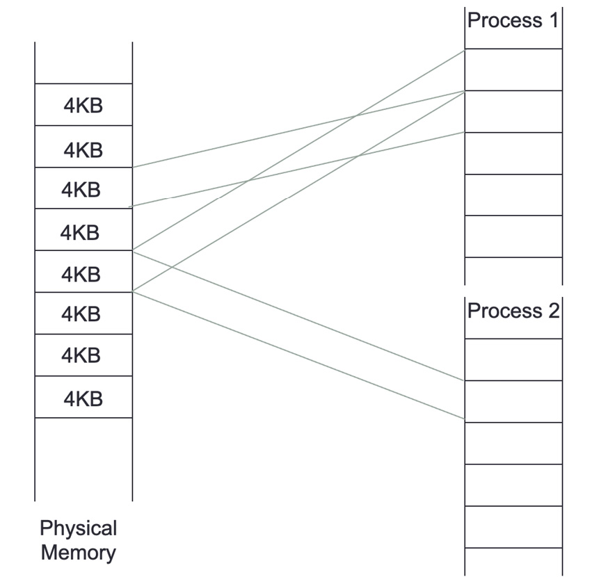
Figure 4.5 – Pages and processes
Translating physical and virtual addresses back and forth is done automatically by hardware in the CPU. For this reason, the performance of the translation would be improved if the information we are translating was in a speedy location close to the CPU. Indeed, a location used to store this information, the page table, will often be in dedicated registers in the CPU, but this is only possible when the page table is tiny. A special-purpose high-speed cache in the CPU called the translation lookaside buffer (TLB) is used for any practical page tables. Since page tables are an in-memory data structure, if the address space for a process is too large to fit inside the TLB, most CPUs have hardware that will pull the relevant page tables into the TLB from other CPUs' caches or even main memory.
Paging can hurt the performance of a process. When there is a cache miss in the TLB, the OS must load data from elsewhere in memory. In HFT systems, we sometimes minimize the impact of the TLB cache miss by increasing the page size. Virtual memory pages larger than the standard base page size of 4 KB are referred to as huge pages. For frequent access patterns on big datasets, huge pages can increase memory speed. Huge pages come with a cost – the TLB that tracks huge pages can sometimes be orders of magnitude smaller than that which manages standard pages, meaning more frequent trips to memory could be needed if you have many huge pages mapped. Thus, huge pages must be used with care.
System calls
A system call means a user space application requests a service from the OS' kernel. A system call is a way for applications to communicate with the OS. A system call is a request from software to the kernel of an OS to perform some sensitive action such as manipulating the hardware state. Some critical system calls on modern OSs are requested to handle process creation and termination, manage files on disk, manage I/O devices, and communicate with the outside world.
When a system call is requested, the kernel will carry out the operation if the request is allowed. For many system calls, if the call is completed successfully, the application receives some response from the kernel. Once the system call is complete, the scheduler can schedule the requesting task to resume if it has time left in its timeslice, or if there isn't a higher priority task waiting for CPU time. The kernel provides the results to the application and then transfers data from kernel space to user space in memory after the procedure is completed.
Some particular system calls, such as getting the system date and time, may take a few nanoseconds to complete. A more extended system call, such as connecting to a network device or interacting with files on disk, may take several seconds. Most OSs launch a separate kernel thread for each system call to minimize bottlenecks. Multi-threaded OSs can handle several system calls at the same time. An HFT system will heavily use this notion of concurrent execution, such as using threads.
Modern versions of Linux provide the virtual dynamic shared object (vDSO) exporting some special kernel space functions to user space, especially those related to retrieving current system time. The power of vDSO is that these functions, under the control of the kernel and thus aware of the hardware specifics, execute directly in the user space process. Unlike open and read system calls that require an entire trip into the kernel (and thus a complete context switch), functions such as clock_gettime (in the case of CLOCK_MONOTONIC at least) have a very low overhead to call because the call is in vDSO.
Threading
The most fundamental division of work in any process is a thread. By doing work across many threads, parallelism may be achieved. All threads inside a single process share a common virtual memory space. Each process, a grouping of one or more threads, has its own unique memory space. The main activity of a trading system is to share data across the different functionalities (potentially processes) to decide to send an order. The use of threads or a process will be considered when optimizing the communication between concurrent functionalities. This also impacts how you structure data being passed between threads and processes. Data passed between threads can take advantage of concurrency in memory allocation, allowing you to pass data by simply giving another thread a pointer to the message in a data structure. Passing data between processes either requires a shared memory pool mapped by both processes or serializing messages into some queue, as discussed in Chapter 6, HFT Optimization – Architecture and Operating System.
On top of being capable of sharing memory, threads have a faster response time than processes. If a process is separated into numerous threads, the output of one thread may be returned promptly as it completes its execution. Their context switch time is also shorter than the one for processes.
Because system calls are required in any HFT system, it is essential to offset the cost. We will see how to benefit from threads and processes in Chapter 6, HFT Optimization – Architecture and Operating System.
Interruption management
Interrupt requests are how peripherals alert the CPU when something has happened. The CPU will then halt one of the processing cores and switch the context to the interrupt handler assigned to that device. Limiting the number of interruptions that can create context switches; we will also return to this in Chapter 6, HFT Optimization – Architecture and Operating System.
Figure 4.6 depicts the impact of using an interruption (or a system call) in a CPU's time executing a task in a single-core model. We can observe that the scheduler will switch between the currently running task and the interrupt context in the kernel. The kernel spends more time on servicing interrupt requests, and then there's less CPU time available to run user tasks.
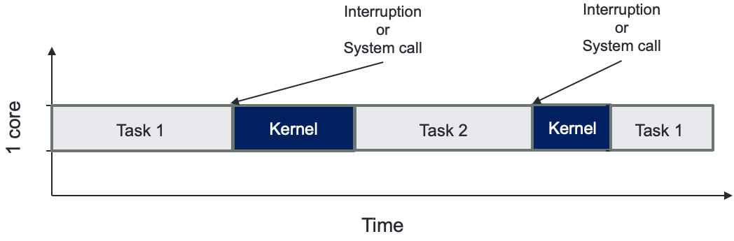
Figure 4.6 – Interruption or system call impact on task scheduling
Figure 4.7 shows the benefit of two CPU cores, having two tasks that do not need to share time. This example shows that if we pin a task to a given core, we will reduce the number of context switches and reduce the impact of kernel interruptions. This example also assumes that interrupt requests are serviced by only one core. Thus, only Task 1 will be disrupted to service hardware.

Figure 4.7 – Advantage of two CPU cores
Chapter 6, HFT Optimization – Architecture and Operating System, details this task scheduling pinning a task to a given core.
In the first two sections, we learned about the hardware, the OS, and their involvement in HFT systems. We will now tackle the last piece: the compilation and libraries, which are also essential to HFT systems.
The role of compilers
Compilers translate human-readable code written in a programming language (the source language) into another language, usually a machine-specific language, though this can be a virtual machine. They translate code from a high-level language to a lower-level one. They can generate intermediate code, assembly languages, object code, or machine code. They also play an essential role in speeding up software runtime. Compilers keep getting smarter by improving the abstraction of what developers wanted to express with efficient execution in hardware. New programming paradigms were added to improve software engineering. In the 1990s, Python and Java made object-oriented programming available to everyone. We recommend that the reader check out the book Compilers: Principles, Techniques, and Tools, also known as the Dragon Book, written by Aho, Lam, Sethi, and Ullman. This book will explain in depth how compilers are designed.
In HFT systems, the compilers can help optimize the part of the code where we spend most of the time: loops. Advanced Compiler Design and Implementation, written by Steven Muchnick, describes the loop optimization that compilers can do. We must keep in mind that the critical part of HFT systems is the space-time tradeoff (increasing memory usage and cache utilization while decreasing execution time). We can talk about a few examples of optimization using this paradigm:
- Loop unrolling is an example of this tradeoff. Because there are fewer iterations when a loop is unrolled, the overhead of exit checks is reduced. Furthermore, there are fewer branch instructions, which may have an overhead depending on the architecture. There are no exit tests in the case of a fully unrolled loop. Unrolling a loop can lead to further optimizations that a compiler can do (for example, in the preceding fully unrolled version, all the array offsets are constants, which is something the compiler may be able to exploit).
- Function inlining can replace the function call by the assembly code of this function itself on the callee side, giving opportunities for more assembly code optimizations.
- Table and calculation. The compilers can help create data structures to avoid recalculation. They will hold values of values already calculated.
The primary function of the compiler is to generate an executable that's runnable by the OS. We will now discuss the executable file formats.
Executable file formats
The compiler and linker convert a high-level program into an executable file format appropriate for the target OS. The OS parses the executable file to figure out how to load and run the program. On Windows, this is a portable executable (PE) file, whereas on Linux, this is an executable and linkable format (ELF) file. Each OS has a loader. The loader determines which chunks of the program on the disk are loaded into memory. The loader allocates the virtual address range that the executable will be using. Then, it will start the execution from the entry point (in the example of the C language, the _start function), which then calls the programmer-defined main function. In terms of memory, it is essential to remember that the OS protects processes from one another by using virtual memory, as we described when discussing virtual memory and paging. Every executable runs isolated in its own virtual address space.
Static versus dynamic linking
Many executable programs on modern systems depend on external code libraries, often provided by third parties, such as an OS vendor. To deal with these external dependencies, there are two ways that a program can integrate this code. The first is by statically linking in all the code, building a standalone binary. The second is by dynamically linking in the external code, requiring the OS to inspect the executable file to figure out which libraries are needed to run the program, loading them separately.
The linker will arrange the application code and dependencies into a single binary object with static linking. Since this binary object has all the dependencies included, there is no opportunity for a program to take advantage of the same library being reused by multiple programs, thus requiring all the code to be loaded separately at runtime. For example, on Linux, many programs utilize the glibc library. If these programs were statically linked, they would waste a lot of memory storing the same dependent library repeatedly. Static linking has a significant advantage: the compiler and linker can work together to optimize all function calls, even with objects pulled in from an external library.
Dynamic linking allows the linker to create a smaller binary file where the dependent libraries' locations would have been replaced with a stub. The dynamic linker will load that library, often on application startup, by loading the appropriate shared object from the disk. Only when the dependency is needed will it be loaded into memory. If multiple running processes use the same library, the library's code's memory can be shared across multiple processes. However, this efficiency comes at a cost: library functions are referenced indirectly when called through the procedure linkage table (PLT). This indirection can lead to added overhead, especially if a short function within the library is called frequently. Typical HFT systems will use static linking where possible to avoid this overhead.
Summary
In this chapter, we developed a conceptual model of how computers work and how to think about the overall performance impact of the various components. Each of the multiple pieces of hardware and software must work in a manner ideal for a trading system. That often requires an understanding of how the hardware and software interact so that the negative impact of inefficient algorithms or interactions can be circumvented or optimized.
Then we are using the fundamentals developed in this chapter as a foundation. The following chapters will build on optimizing the OS, kernel, and application for HFT systems. This will include reducing the impact of context switching, techniques for safely accessing shared data structures, and other means of mitigating inefficient components of the underlying hardware and software.
The next chapter will focus on networking. We will explain the role of a network card for HFT systems and how communication with the exchange needs to be optimized to reduce latency.