GMP in Pharma Manufacturing—Description of GMP as Related to Air-Handling Units and Prevention of Contamination and Implementation of GMP Regulatory Requirements
S. Lakshmana Prabu1, T.N.K. Suriyaprakash2, K. Ruckmani1 and R. Thirumurugan3, 1Anna University, Tiruchirappalli, Tamil Nadu, India, 2Al Shifa College of Pharmacy, Kerala, India, 3International Medical University, Kuala Lumpur, Malaysia
Abstract
Drug substances and drug products are used for treating various diseases to save the lives of human beings. Drug substances and drug products should be manufactured using clean equipment with appropriate quality and in good environmental condition to avoid contamination of the product and to produce the desired therapeutic effect. Effort should be made to build quality into the product during each stage of the manufacturing process rather than simply testing the product. To regulate the manufacturing process, regulatory agencies along with pharmaceutical industrial organizations developed good manufacturing practice (GMP) guidelines for the preparation/manufacturing of the drug substance and drug products. Various GMP guidelines are followed in respective regions in the world even though the fundamentals of all the guidelines remain the same. The GMP guidelines consist of various processes including quality management, personnel, personal hygiene and qualification, building and facilities, sanitation, documentation and records, material management, production and in-process controls, packaging and labeling of drug substances and drug products, storage and distribution, laboratory controls, validation, rejection and reuse of materials, complaints and recalls, and change control. Clean equipment, cleanrooms, and environmental conditions are critical process parameters to be monitored strictly in the manufacturing process to ensure the highest standard of quality and purity of the product with desired safety and efficacy of the drug product to meet the regulatory requirements.
Keywords
Good manufacturing practices; contamination; pharmaceutical industry; pharmaceutical manufacturing; guidelines; regulatory agencies; regulatory requirements; implementation; validation; manufacturing facilities; air handling; cleanroom; heating ventilation air conditioning; validation
1 Introduction
To deliver drug products to the public with the highest standards of quality, purity, and safety with the desired efficacy, the pharmaceutical industries have traditionally cooperated with various regulatory bodies. The combined efforts of the pharmaceutical industry and the regulatory agencies are reflected as good manufacturing practices (GMPs) regulation; GMP regulates the production, distribution, and supply of a drug product/substance. The current advanced GMPs regulations are called current good manufacturing practices (cGMPs). Globally various regulatory bodies have their own GMPs for regulating the manufacturing of drug products, but the basic concepts of all the GMP guidelines are similar: the aim is to safeguard the health of the patients with the highest standards of quality, purity, and safety with the desired efficacy of the drug product and without any contamination.
1.1 How Were GMPs Developed?
A major drug tragedy in 1960 led to the passage of the Kefauver–Harris amendments to the United States Federal Food, Drug, and Cosmetic Act of 1938. A new synthetic drug, thalidomide, was recommended by a physician’s prescription as a sleeping pill and to treat morning sickness. Thalidomide was a drug that replaced the barbiturates in popular use as a sedative. Thalidomide was given to women during pregnancy. The children whose mothers took thalidomide in the first trimester were severely affected; the drug caused the arrested development of the limbs of the fetus. Some children were born with severely deformed arms and legs, and some were born with neither arms nor legs, others with only partially formed limbs. The more fortunate were born with only disfigurations of the nose, eyes, and ears. More severely affected children died within few hours after birth.
The reason why more American children were not harmed had been because of resistance by the United States Food and Drug Administration (FDA) to marketing of the drug until proof of safety had been established. Two legislators, Estes Kefauver and Oren Harris, pushed more stringent legislation through the U.S. Congress. As a result, a very strong bill was passed in October 1962 (the Kefauver–Harris Amendment). The Kefauver–Harris Amendment states that the company must not only prove the safety of the drug but also ensure the efficacy of the intended use of the particular drug product. Based on the amendment, the FDA then proceeded to issue its first cGMPs guidelines in 1963. In 1968 new power was given to the FDA to inspect the pharmaceutical firms to ensure the GMP was followed on their premises [1,2].
2 GMP Guidelines
GMPs are general principles that need to be followed during the manufacturing of drug products to ensure the highest standards of quality, purity, and safety with the desired efficacy. Every company should have an effective and efficient quality process to ensure the quality of the products. GMP is effective in more than 100 countries ranging from Afghanistan to Zimbabwe. Various GMP guidelines are framed with respect to their region, but the basic concepts of all the GMP guidelines are similar.
Various GMP guidelines have appeared in several countries:
1. Pharmaceutical Inspection Convention (PIC) guide to GMP for pharmaceutical products in Australia, Austria, Belgium, Canada, Denmark, Finland, France, Hungary, Ireland, Italy, Latvia, Liechtenstein, Malaysia, the Netherlands, Norway, Poland, Portugal, Romania, Singapore, Slovak Republic, Spain, Sweden, Switzerland, and the United Kingdom.
2. Association of Southeast Asia Nations (ASEAN) GMP guidelines cover Brunei Dar-us-Salaam, Cambodia, Indonesia, Lao People’s Democratic Republic, Malaysia, Myanmar, Philippines, Singapore, Thailand, and Vietnam.
3. European Economic Community (EEC) guide to GMP for medicinal products in Austria, Belgium, Denmark, Finland, France, Germany, Greece, Ireland, Italy, Luxembourg, the Netherlands, Portugal, Spain, Sweden, and the United Kingdom [1].
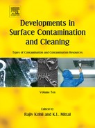
Pharmaceutical regulators and pharmaceutical industries in more than 100 countries follow GMPs issued by the World Health Organization (WHO). Generally, inspection of the premise is performed by the national regulatory agencies. Regulatory bodies of the different countries are given in Table 3.1.
Table 3.1
Regulatory Bodies of the Different Countries [3]
| Countries | Regulatory Bodies |
| United States of America | FDA |
| United Kingdom | Medicines and Healthcare Products Regulatory Agency |
| Australia | Therapeutical Goods Administration (TGA) |
| South Africa | Medicines Control Council (MCC) |
| Brazil | National Health Surveillance Agency Brazil |
| India | Central Drug Standard Control Organization (CDSCO) |
| Hong Kong | Department of Health |
| Singapore | Ministry of Health: Health Sciences Authority |
| Philippines | Department of Health |
| Thailand | Ministry of Public Health Food and Drug Administration |
| Malaysia | Malaysia: Ministry of Health |
| Malaysia: National Pharmaceutical Control Bureau | |
| Indonesia | Ministry of Health |
| China | People’s Republic of China: Ministry of Health (in Chinese) |
| People’s Republic of China: State Drug Administration (in Chinese) | |
| People’s Republic of China: National Institute for the Control of Pharmaceutical and Biological Products (in Chinese) | |
| United Arab Emirates | Ministry of Health |
| South Korea | Food and Drug Administration |
| Egypt | Egyptian Drug Authority (EDA) |
| Oman | Ministry of Health, Directorate General of Health Services Muscat |
| Kuwait | Ministry of Health |
2.1 Need for GMP Monitoring System
The manufacturing of a drug product has to be monitored in the pharmaceutical industry; this is a specific requirement for the regulatory bodies to ensure the highest standards of quality, purity, and safety with the desired efficacy of the drug product.
2.1.1 Monitoring Key Parameters in GMP
The key parameters in GMP monitoring are:
![]() critical quality attributes of the product;
critical quality attributes of the product;
![]() quality of the intermediate product;
quality of the intermediate product;
![]() quality of water and performance of the water system;
quality of water and performance of the water system;
![]() environmental monitoring systems for microbial contamination;
environmental monitoring systems for microbial contamination;
![]() effectiveness of equipment cleaning;
effectiveness of equipment cleaning;
![]() performance of process procedures and personnel;
performance of process procedures and personnel;
2.1.2 Locations to be Monitored
Locations to be monitored include:
![]() points at which problems are known to occur during the manufacturing process;
points at which problems are known to occur during the manufacturing process;
![]() critical areas, where the product can be expected to have highest vulnerability;
critical areas, where the product can be expected to have highest vulnerability;
In addition, the value of microbial and particulate data during human or machine activities should be monitored.
2.1.3 Ways to Monitor
![]() graphical representation of the collected data evaluation;
graphical representation of the collected data evaluation;
![]() establishing the critical level and action level of the critical process;
establishing the critical level and action level of the critical process;
![]() action to be taken if any issues are identified in the critical process;
action to be taken if any issues are identified in the critical process;
![]() frequency of sample collection which depends on the nature of the operation in the manufacturing process [4].
frequency of sample collection which depends on the nature of the operation in the manufacturing process [4].
2.2 Components of GMP
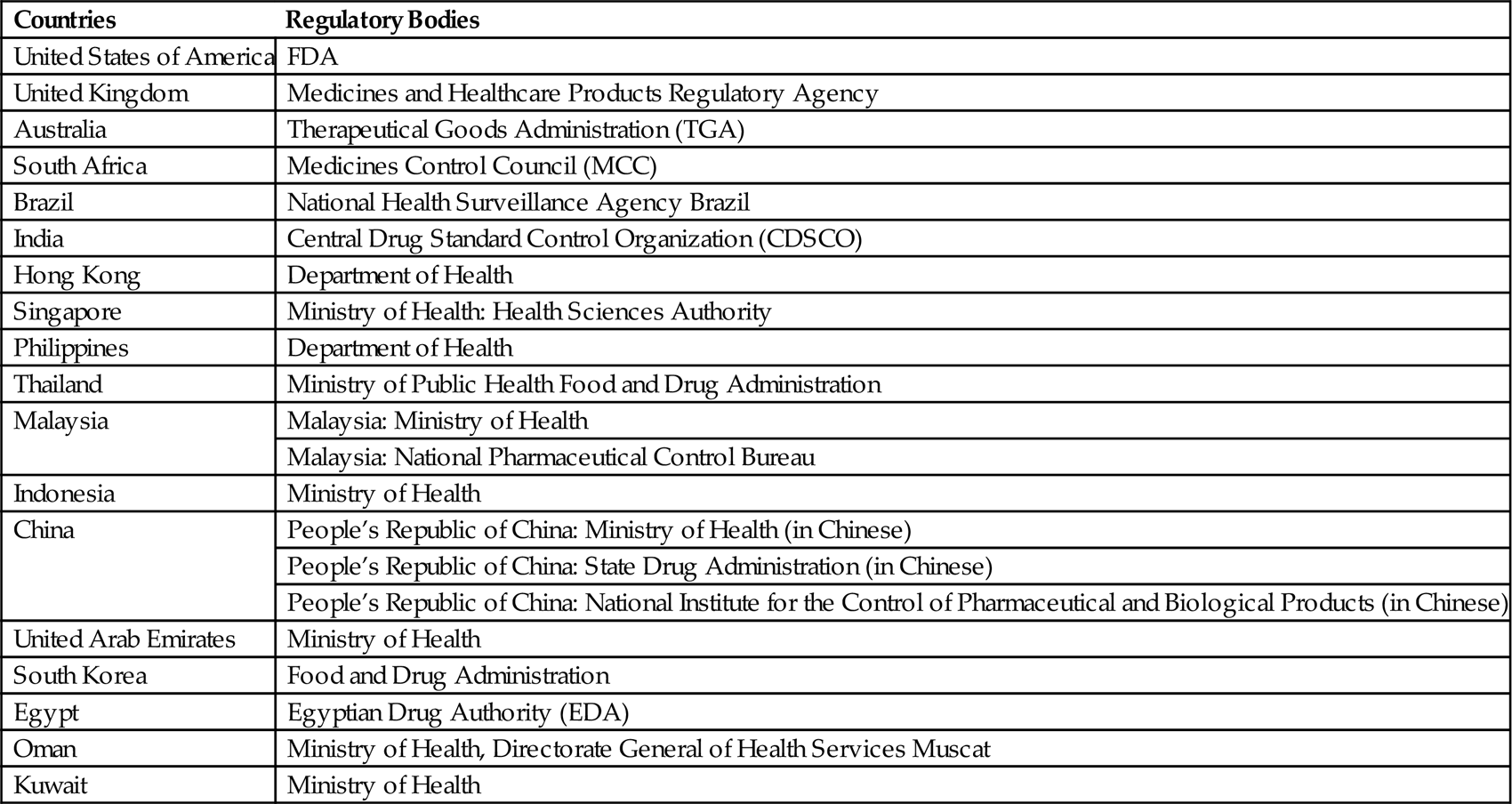
Table 3.2 compares GMP among the different published guidelines. The chapter numbers refer to the titles of the individual chapters in the respective guidelines, except for the FDA guidelines, which use subpart numbers.
Table 3.2
Comparative GMP Among the Various Guidelines [5–12]
| Content | South Africa | ASEAN | European Commission | PIC/S | ICH | WHO | FDA | TGA |
| Chapter 1/Subpart Aa | Quality management | Quality management | Pharmaceutical quality system | Quality management | Quality management | Pharmaceutical quality system | General provisions | Quality management |
| Chapter 2/Subpart B | Personnel | Personnel | Personnel | Personnel | Personnel | Good manufacturing practices for pharmaceutical products | Organizational and personnel | Personnel |
| Chapter 3/Subpart C | Premises and equipment | Premises and equipment | Premises and equipment | Building and facilities | Building and facilities | Sanitation and hygiene | Building and facilities | Premises and equipment |
| Chapter 4/Subpart D | Documentation | Sanitation and hygiene | Documentation | Process equipment | Process equipment | Qualification and validation | Equipment | Documentation |
| Chapter 5/Subpart E | Production | Documentation | Production | Documentation and records | Documentation and records | Complaints | Control of components and drug product containers and closures | Production |
| Chapter 6/Subpart F | Quality control | Production | Quality control | Materials management | Materials management | Product recalls | Production and process controls | Quality Control |
| Chapter 7/Subpart G | Contract manufacture and analysis | Quality control | Outsourced activities | Production and in process control | Production and in process control | Contract production, analysis, and other activities | Packaging and labeling control | Contract manufacture and analysis |
| Chapter 8/Subpart H | Complaints and product recall | Contract manufacture and analysis | Complaints and product recall | Packaging and identification labeling of APIs and intermediates | Packaging and identification labeling of APIs and intermediates | Self-inspection, quality audits, and suppliers’ audits and approval | Holding and distribution | Complaints and product recall |
| Chapter 9/Subpart I | Self-inspection | Complaints and product recall | Self-inspection | Storage and distribution | Storage and distribution | Personnel | Laboratory controls | Self-inspection |
| Chapter 10/Subpart J | Self-inspection | Laboratory control | Laboratory control | Training | Records and reports | |||
| Chapter 11/Subpart K | Validation | Validation | Personal hygiene | Returned and salvaged drug products | ||||
| Chapter 12 | Change control | Change control | Premises | |||||
| Chapter 13 | Rejection and reuse of materials | Rejection and reuse of materials | Equipment | |||||
| Chapter 14 | Complaints and recall | Complaints and recall | Materials | |||||
| Chapter 15 | Contract manufacturing | Contract manufacturing | Documentation | |||||
| Chapter 16 | Agents, brokers, traders, distributors, repackers, and relabelers | Agents, brokers, traders, distributors, repackers, and relabelers | Good practices in production | |||||
| Chapter 17 | Good practices in quality control |
PIC/S, Pharmaceutical Inspection Convention and Pharmaceutical Inspection Cooperation Scheme; ICH, International Council on Harmonization.
aFDA guidelines use subpart numbers for the titles of individual chapters.
2.3 Quality Management Systems in GMP
2.3.1 Pharmaceutical Quality System
Traditional drug products should be manufactured with the compliance of the national regulatory authority and delivered to the public with the highest standards of quality, purity, and safety with the desired efficacy, and should not place patient/public health at risk due to inadequate safety and quality of the drug product.
To maintain the quality of the drug products is the responsibility of all the employees in different departments who are involved at all levels in the manufacturing process within the organization. To ensure and achieve the quality of the product and promote the uniformity of the product, a set of standards has been designed to incorporate the GMP and implement it in the development, manufacture, and control of medicinal products with documentation of its effectiveness monitoring system.
2.3.2 Quality Assurance
The basic concept of quality assurance is that it includes all matters that individually or collectively influence the quality of a product. The role of quality assurance starts from management of the raw material quality, packaging materials, intermediate and finished products in production, and management and inspection processes. It is also applied to ensure that the facilities meet the specification of the regulatory requirements during the manufacturing of the drug product by self-inspection to comply with the effectiveness and applicability of the quality assurance systems.
2.3.3 Good Manufacturing Practices
GMPs are a part of quality assurance to ascertain that the products manufactured are produced consistently to achieve the desired quality and uniformity by following the quality standards to meet the product specification and regulatory requirements of the FDA and other regulatory bodies.
The necessary facilities required for manufacturing of drug products under GMP include:
2.3.4 Quality Control
Quality control (QC) is a part of GMP. Responsibilities of the QC department are:
![]() sampling, which includes raw materials, intermediate production samples, finished products, and packaging materials;
sampling, which includes raw materials, intermediate production samples, finished products, and packaging materials;
![]() analyzing the samples as per the specifications of the relevant tests;
analyzing the samples as per the specifications of the relevant tests;
![]() documentation of the results obtained;
documentation of the results obtained;
![]() approving or rejecting the raw materials, intermediate production samples, finished products, and packaging materials;
approving or rejecting the raw materials, intermediate production samples, finished products, and packaging materials;
![]() releasing the approved samples for production or sale after achieving satisfactory analytical results;
releasing the approved samples for production or sale after achieving satisfactory analytical results;
![]() reviewing the production records to assure that the products meet the desired specifications and regulatory requirements;
reviewing the production records to assure that the products meet the desired specifications and regulatory requirements;
![]() retaining the specified quantity of reference samples (starting materials and finished products in the final package) if any necessary future examination is required for the product.
retaining the specified quantity of reference samples (starting materials and finished products in the final package) if any necessary future examination is required for the product.
2.3.5 Product Quality Review
Product quality review should be conducted periodically for all drug products to ensure that the products are manufactured with the desired quality and uniformity by following the product specifications to meet the regulatory requirements.
Product quality review includes:
![]() review of starting materials used in production, which includes active pharmaceutical ingredients, excipients, and packaging materials;
review of starting materials used in production, which includes active pharmaceutical ingredients, excipients, and packaging materials;
![]() review the critical in-process control points and results of the finished product analysis;
review the critical in-process control points and results of the finished product analysis;
![]() review any out-of-specification and significant deviation in the batch manufacturing, as well as the corrective measures, and implementation of the corrective actions;
review any out-of-specification and significant deviation in the batch manufacturing, as well as the corrective measures, and implementation of the corrective actions;
![]() any dossiers submitted for registration;
any dossiers submitted for registration;
![]() review of stability study results of the new drug products;
review of stability study results of the new drug products;
![]() any complaints and recall products and results of their investigation;
any complaints and recall products and results of their investigation;
![]() review of any new product registration;
review of any new product registration;
![]() review of validation studies of equipment, cleaning validation, water system, and air-handling units [5–15].
review of validation studies of equipment, cleaning validation, water system, and air-handling units [5–15].
3 Organization and Personnel
Every manufacturing unit will have an organization chart. Each department’s employees will have specific job descriptions along with responsibility to carry out their daily activities. Designations of the employee are based on their educational qualification and experience, whereas the GMP regulations do not specify the education, knowledge, skills, or experience required for the different types of jobs within a pharmaceutical company. In general, the organization structure of a pharmaceutical company has two main departments, namely, production and QC, which are independent of each other. The quality assurance department is the coordinating department between production and QC. Adequate numbers of qualified personnel are needed to be appointed to perform and supervise the manufacturing, processing, packaging, or retention of each drug product.
Employees are selected based on their basic skills, such as reading, writing, and work experience, along with specialized educational qualification. Before appointing any employee he/she has to undergo a medical fitness examination, which includes medical history, X-ray (chest), Wassermann test, tuberculosis test, and color blindness test. Employees should produce the medical fitness certificate from the physician referred by the company. After appointment, there shall be an initial induction program that briefs the company policies, rules and regulations, job description, and responsibilities. After the initial induction, there is a basic training program for a specific period of time to understand the working principles of that particular organization. During the training, the employee will be closely observed to ensure understanding of the techniques related to their job responsibility. After the training program, they will be assessed on lessons learned and practical skills of their jobs. Based on the evaluation report, repeat training may be initiated if necessary. If any employees avail sick leave, the employees are advised to obtain and produce a medical fitness certificate from the physician before returning to their regular work.
In manufacturing areas, employees are advised to wear the plant uniform to maintain adequate standards in the manufacturing location. Wearing plant uniform is important to protect the drug product from potential contamination from the employees, including hair, fibers from dress material, contamination from cloth, outside dust, or microorganisms shed from skin and from the mouth and nose.
Specific concerns about the plant uniform include:
1. Adequate number of clean uniforms must be provided to the employees.
2. Cleaning and the procedure to maintain sanitation should be checked to confirm their effectiveness.
3. Employees are advised to wear lint-free garments while entering into the specific area to avoid shedding.
4. The plant uniform must provide comfort to the employees.
5. The range of clothing available as plant uniform covers:
b. beard and moustache covers;
c. coveralls, preferably with no pockets, or pockets suitably designed to prevent articles from falling out;
h. appropriate cleanroom suits for sterile areas.
6. Training provided to the employee should show how and when to wear the appropriate clothing in the production areas.
7. Plant uniform should be removed and kept in the change room whenever the employees leave the manufacturing areas.
3.1 Responsibilities of Various Departments
3.1.1 Production Department
The head of the production department should have adequate knowledge in various manufacturing processes with good practical experience.
Responsibilities of production department head include:
![]() ensuring that the products manufactured and stored on the premises have required quality and are documented;
ensuring that the products manufactured and stored on the premises have required quality and are documented;
![]() approving and implementing the production operation instructions effectively;
approving and implementing the production operation instructions effectively;
![]() ensuring the batch manufacturing records are signed by the designated staff;
ensuring the batch manufacturing records are signed by the designated staff;
![]() ensuring the equipment used in the production are clean and maintained properly;
ensuring the equipment used in the production are clean and maintained properly;
![]() verifying the critical processes in the manufacturing process.
verifying the critical processes in the manufacturing process.
3.1.2 QC Department
The head of the QC department should have adequate training with good practical experience. He/she should have individual authority to approve the materials that meet specifications or reject the materials that do not meet specifications.
Responsibilities of the QC department head include:
![]() approving or rejecting the materials utilized in manufacturing such as starting materials, packaging materials, and intermediate and finished products;
approving or rejecting the materials utilized in manufacturing such as starting materials, packaging materials, and intermediate and finished products;
![]() verifying the batch manufacturing records;
verifying the batch manufacturing records;
![]() verifying and ensuring all tests are performed on the materials utilized in the manufacturing;
verifying and ensuring all tests are performed on the materials utilized in the manufacturing;
![]() approving and implementing the instructions of the QC operation effectively;
approving and implementing the instructions of the QC operation effectively;
![]() ensuring the equipment used in the QC operations are clean and calibrated according to the time schedule;
ensuring the equipment used in the QC operations are clean and calibrated according to the time schedule;
![]() fixing the expiration date/shelf-life of the drug products based on their stability test results;
fixing the expiration date/shelf-life of the drug products based on their stability test results;
![]() maintaining the analytical records of the starting materials, packaging materials, intermediate and finished products;
maintaining the analytical records of the starting materials, packaging materials, intermediate and finished products;
![]() providing adequate training to department personnel whenever required.
providing adequate training to department personnel whenever required.
3.1.3 Shared Responsibilities Between the QC Head and Production Department Head
Shared responsibilities between the QC head and production department head include:
![]() monitoring the manufacturing facility environment, sanitation, and hygiene of the persons engaged in manufacturing;
monitoring the manufacturing facility environment, sanitation, and hygiene of the persons engaged in manufacturing;
![]() verifying the critical processes and ensure their quality with respect to their specification;
verifying the critical processes and ensure their quality with respect to their specification;
![]() establishing the storage conditions for the materials and drug products and monitor the storage conditions;
establishing the storage conditions for the materials and drug products and monitor the storage conditions;
![]() approving and monitoring the suppliers and the contract manufacturers;
approving and monitoring the suppliers and the contract manufacturers;
![]() providing adequate training to personnel who require training;
providing adequate training to personnel who require training;
![]() maintaining batch records and related analytical records of the materials used in the manufacture of that particular batch;
maintaining batch records and related analytical records of the materials used in the manufacture of that particular batch;
3.1.4 Personal Responsibilities of Employees in Manufacturing Premises
1. Each person should practice good sanitation and health habits in the manufacturing area.
2. Those persons who are engaged in the manufacturing, processing, packaging, or holding the drug product should wear the clean clothes that are appropriate for their job description. Protective items like head covers, face masks, and hand and arm coverings are required for those persons who handle the drug product to avoid contamination.
3. Only responsible persons should be allowed to enter the restricted areas (aseptic areas) to avoid contamination.
4. Any ill persons should inform their supervisor about their health condition. Persons who have any illness are advised to avoid direct contact with the drug products, containers, and closures in the manufacturing process [5–12,16,17].
4 Building and Facilities
There are various factors that need to be considered while selecting the location of the manufacturing facility, which include legal concerns, real estate, state and local government agencies, utility companies, engineers, architects, and financial incentives for building in specific geographical locations.
External and internal environments are the two main concerns about the building and facilities. The external environment consists of the location of well-designed and constructed buildings of suitable size.
The site development plan should consider the following:
1. Appropriate law and regulations and compliance with additional company standards
2. Appropriate amenities, access to rapid transportation, storage facilities, and protection against the environment
3. Drainage and waste management
4. Plant security and controlled access
6. Accessories: design, layout, and backup
7. Equipment: appropriate design, spacing, and availability of spares
8. Safety precautions and emergency services access
9. Movement: internal and external
10. Ease of maintenance: accessibility to services, ease of cleaning, and access of the equipment
11. Validation plan and an effective change control procedure
12. Provision of design and as-built drawings
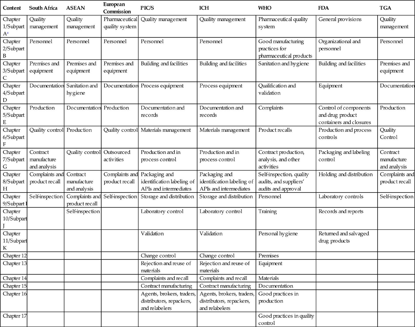
13. Construction materials (Table 3.3):
a. Walls. Walls should provide an orderly movement of materials and personnel, should minimize cross-contamination, and also minimize noise levels to provide acceptable working conditions. Walls in the manufacturing areas, corridors, and packaging areas should be of plaster finish on high-quality concrete blocks or gypsum board with smooth finish using enamel or epoxy paints.
b. Floors. Floor covering should have durability as well as cleanability and resistance. Terrazzo provides hard-wearing finish. Ceramic and vinyl tiles usually are not recommended for production area. Vinyl sheets provide an even, easy-to-clean surface. Epoxy flooring provides a durable and readily cleanable surface.
c. Ceilings. Suspended ceilings may be provided in office areas, laboratories, toilets, and cafeterias.
Table 3.3
Ideal Finishes Required in the Manufacturing Premises [18]
| Area | Walls | Floors | Ceilings |
| Warehouse | Painted | Hardened concrete; sealed | |
| Dispensary | Epoxy covered | Epoxy or in situ terrazzo covered | Epoxy covered |
| Solids manufacturing | Epoxy covered | Epoxy or in situ terrazzo covered | Epoxy covered |
| Liquids manufacturing | Epoxy covered | Epoxy or in situ terrazzo covered | Epoxy covered |
| Solids packaging | Painted | Sealed concrete, terrazzo tile, or vinyl | Suspended ceiling |
| Liquids packaging | Epoxy covered | Epoxy or in situ terrazzo covered | Epoxy covered |
| Laboratory | Epoxy | Terrazzo tile or epoxy sheet | Suspended ceiling |
The selection and construction layout of the building should have sufficient space and should minimize the risk of mix-up or contamination by providing adequate separation for various manufacturing operations. At the time of designing the building, the flow of materials to be processed or movement of personnel should be curtailed. There is also a need to consider the layout of the facilities and the operations for visitors without the need to enter the manufacturing premises.
Manufacturing operations should be performed in specific areas to prevent mix-ups or contamination. Various manufacturing operations include:
1. receiving, identification, storage, and withholding from use of components, drug product containers, closures, and labels in receiving quarantine;
2. storage and quarantine of the rejected components, drug product containers, closures, and labeling before disposition;
3. sampling of staring materials and packaging materials for analysis;
4. storage of released starting materials, drug product containers, closures, and labeling;
5. storage of approved starting materials, drug product containers, closures, and labeling;
6. weighing and dispensing of materials for production;
7. storage of in-process or intermediate materials;
8. manufacturing and processing operations;
9. packaging and labeling operations;
10. quarantine storage of finished drug products;
4.1 Storage Area
The receiving area is an access point for airborne contamination, when materials are unloaded by the delivery transports. Airborne contamination can be prevented by installing flexible curtains, which minimizes the space between unloading areas, along with fixing the air curtains between the receiving bays and the warehouse, which may provide additional protection to the materials from airborne contamination.
The storage area should have sufficient space to separately store the starting materials (liquids and solids), packaging materials, and finished products before QC approval and after QC approval, and rejected materials to ensure good storage conditions (temperature and humidity). Rejected materials should be kept under secure conditions to prevent mix-up. Starting materials that have hazardous characteristics, like flammable, explosive, toxic, and corrosive chemicals, should be kept separately under secure conditions to avoid any hazards.
A separate sampling area needs to be provided for starting materials, because the starting materials are exposed to ambient conditions for a short duration during sampling. After sampling, the sampling area needs to be cleaned with a disinfectant to avoid contamination. A record for the cleaning of the sampling area should be maintained. Different disinfectants are recommended for use for a period of time to prevent resistance of the strains of microorganisms against the disinfectant. Various disinfectants used on the premises are ethanol, phenol, formaldehyde, isopropanol, iodine and iodophors, chlorine compounds (hypochlorite, chloramine, etc.), and quaternary ammonium compounds [1]. Printed packaging materials should be kept in a secure place to ensure conformity of the products. The finished products are stored in ambient conditions, usually between 20°C and 25°C, in the warehouse before dispatch.
The rejected materials are kept for as short a time as possible in the storage area, because the FDA investigators consider that the presence of rejected materials gives an indication of the violation of GMP in the manufacturing.
4.2 QC Area
QC laboratories should be separate from the production areas. Sufficient space should be provided to prevent cross-contamination of the materials. Sophisticated analytical equipment should be kept in a separate room and free from any vibrations, electrical interference, and humidity. A microbiological laboratory includes a media preparation room and sterile room for microbiological studies. A normal laboratory space should be provided to perform general tests on the starting materials and packaging materials. A specific area needs to be provided for preparation of the analytical documents and safe storage of the analytical documents.
4.3 Production Area
Changing rooms leading into the production area should have adequate handwashing and sanitizing facilities. They should be separated from the production area, but should have a direct connection to the entrance into the processing area. The production area should be designed to logically connect the corresponding sequence of operations and to maintain effective cleanliness levels in the individual areas.
In the production area, both packaging materials and drug substances are exposed to the environment. The production area should have good ventilation for the visual online controls of the condition of the ambient air, including temperature, humidity, and filtration to ensure that the facility is suitable to prevent contamination.
Inner surfaces such as walls, floors, and ceilings should be smooth, and free from cracks and open joints for easy and effective cleaning and to avoid shedding of particulate matter. Open channels should be avoided. Separate areas should be provided for the production of semisolid dosage-form preparations (products intended for external use) and finished products intended for internal consumption. If any dust is generated during the operations, the flow of air is adjusted to meet the varying needs of the different processing areas. Separation of the manufacturing and process operations individually depends on the nature of operations. Frequent analysis of the air samples confirms that the potential for cross-contamination is negligible.
Packaging and labeling operation areas should be specifically designed in a separate area away from the manufacturing area to avoid cross-contamination. More attention needs to be given to the online storage of bulk products, labeling, and filled but unlabeled containers.
4.4 Ancillary Area
Rest and refreshment rooms and toilets should be separated and should not have direct access to the storage, QC, and production areas. Sufficient numbers of facilities need to be provided for changing clothes, washing, and toilet purposes.
Maintenance workshops should be separated from the production areas. Animal houses should be well isolated from other areas, which should have separate entrances (animal access) and air handling facilities.
4.5 Lighting
Adequate lighting should be provided in all areas. Normally between 30 and 50 foot-candles provides adequate comfort for effective and efficient working conditions for the workers (Table 3.4). In some ancillary areas 100 foot-candles may be provided. Special lighting facilities using sodium vapor lamps may be provided in specific areas used for sampling or dispensing of light-sensitive materials to avoid photodegradation. One foot-candle is defined as the amount of illumination the inside surface of a 1-foot-radius sphere would receive if there were a uniform point source of 1 candela in the exact center of the sphere [5–12,18].
Table 3.4
Lighting Illumination Intensity in Specific Areas of the Premises [1,19]
| Illumination Intensity (lux) | Specific Areas |
| 20 | Narrow corridor, aisle |
| 50 | Warehouse of big size containers, corridor for personnel traffic |
| 100 | Corridor for traffic of personnel and forklift, breakroom locker room, restroom, utility rooms, staircase lobby |
| 200 | Workshop, warehouse |
| 300 | Laboratory |
| 500 | Offices with reading activities, production room, first-aid room |
| 750 | Drafting room |
| 1000 | Visual inspection |
5 Heating, Ventilation, and Air Conditioning (HVAC) System
5.1 Importance of HVAC
![]() Heating the air provides adequate temperature in the room during adverse weather conditions. Air is heated either locally or centrally on the premises. Heating the air at a central location is commonly performed due to cost. Various heating devices such as furnaces, boilers, heating pumps, and radiators are commonly used.
Heating the air provides adequate temperature in the room during adverse weather conditions. Air is heated either locally or centrally on the premises. Heating the air at a central location is commonly performed due to cost. Various heating devices such as furnaces, boilers, heating pumps, and radiators are commonly used.
![]() Ventilation is associated with air movement in the cleanroom. Ventilation is necessary for exchange of expelled carbon dioxide and to inhale fresh oxygen in the cleanroom. Ventilation provides comfort to the operator and avoids airborne contamination. Insufficient ventilation promotes bacteria and fungi growth in that location [20–22].
Ventilation is associated with air movement in the cleanroom. Ventilation is necessary for exchange of expelled carbon dioxide and to inhale fresh oxygen in the cleanroom. Ventilation provides comfort to the operator and avoids airborne contamination. Insufficient ventilation promotes bacteria and fungi growth in that location [20–22].
5.2 HVAC System
Drug products are utilized for treating various diseases; hence natural ventilation is not acceptable because of the risk of product contamination by physical, chemical, and microbiological sources. The windows in the production area are preferably fixed and remain closed to avoid product contamination. Temperature and humidity are the two main factors that need to be controlled primarily for the comfort of the operators and contamination vulnerability of the product. The earth is an amazing, nurturing environment for microorganisms that are widely distributed across different environments. Microbial and nonviable particulates in the air are the most critical factors in an aseptic processing area.
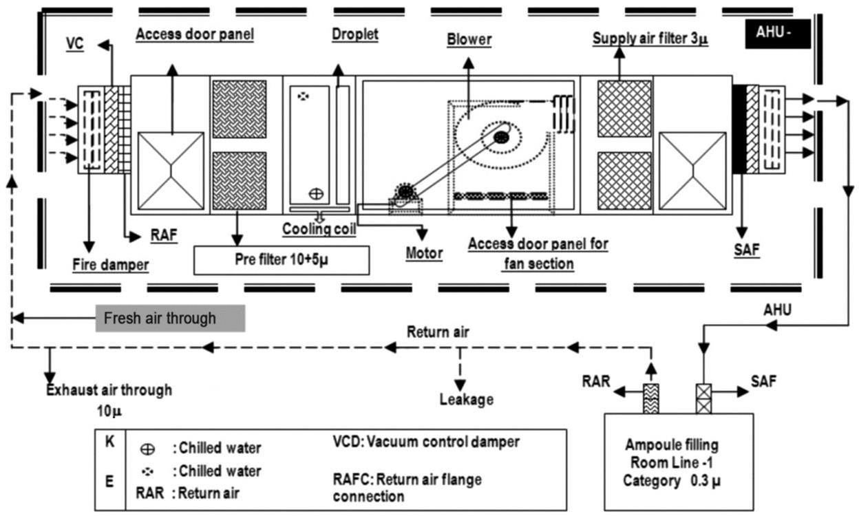
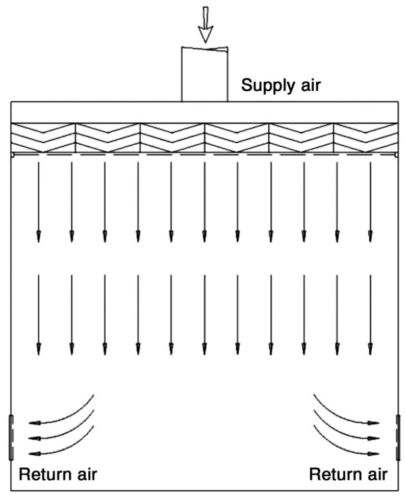
A critical area is the area in which the sterilized drug product, containers, and closures are exposed to environmental conditions. The exposed products are vulnerable to contamination; consequently, they may not be able to be sterilized in their immediate containers. One aspect of environmental quality is the particle content of the air, which can enter into a product as contaminant and also act as a vehicle for microorganisms. Control of airborne particulates in indoor environments is critical to develop quality products, protect employees from contact with hazardous materials, or prevent health problems from prolonged exposure to allergens. Air filtration through the heating, ventilation, and air conditioning (HVAC) system is designed to provide a cleanroom and aseptic environmental facility for the manufacturing of sterile drug products and provide safety to the employees. Appropriately designed air handling systems minimize particle content in a critical area. The air entering into the air handling unit is filtered by prefilters and medium filters and supplied to the cleanroom at sufficient velocity to sweep away the settled particles and maintain unidirectional airflow during the operation. The air velocity is established based on the cleanroom classification. Before entering the cleanroom, the air is terminally filtered through high efficiency particulate air (HEPA) filters to meet the GMP requirements. These filters can remove roughly 99.97% of all microparticles in the room supply air by applying either laminar airflow or turbulent airflow techniques to the environment air [22–27]. The design and function of a typical HVAC system are shown in Fig. 3.1 [24].
5.3 Cleanroom Classification
The grade classification of cleanrooms is given below.
![]() Grade A: The local zone for high-risk operations includes aseptic filling zone, stopper bowls, open vials, and making aseptic connections. This zone is equipped with laminar flow systems with homogeneous air speed in the range of 0.36–0.54 m/s.
Grade A: The local zone for high-risk operations includes aseptic filling zone, stopper bowls, open vials, and making aseptic connections. This zone is equipped with laminar flow systems with homogeneous air speed in the range of 0.36–0.54 m/s.
![]() Grade B: This is the background environment for grade A zones.
Grade B: This is the background environment for grade A zones.
![]() Grade C: Clean areas for carrying out less critical stages in the manufacture of sterile products.
Grade C: Clean areas for carrying out less critical stages in the manufacture of sterile products.
![]() Grade D: This area is unclassified, as it is meant for the capping and gowning room and black/gray change room [28].
Grade D: This area is unclassified, as it is meant for the capping and gowning room and black/gray change room [28].
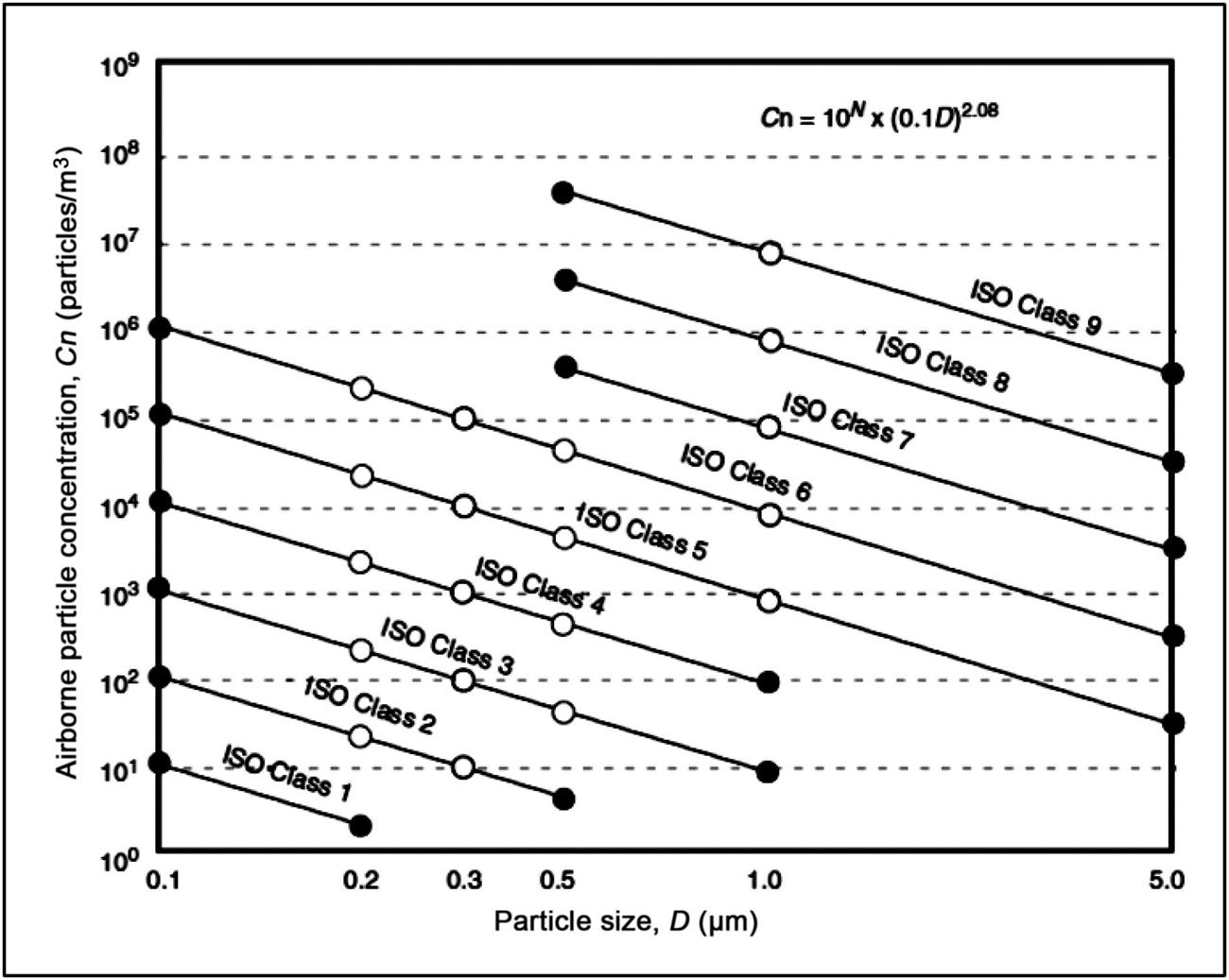
The limits for the various cleanroom classifications are determined by
(5.1)
where Cn is the maximum permitted concentration (particles/m3); D is the particle size in cm; 10N is the classification number.
If the particle size is plotted against its concentration on a log/log scale, the slope of the curve for each class is 2.08 as shown in Fig. 3.2 [29].
Various International Organization for Standardization (ISO) cleanrooms and a comparison of different airborne particulate classifications are shown in Tables 3.5 and 3.6.
Table 3.5
ISO Airborne Particulate Cleanliness Classes for Cleanrooms and Clean Zones [30,31]
| Classification Number (N) | Maximum Concentration Limits (Particles/m3 of Air) for Particles Equal to or Larger Than the Considered Sizes Shown Below | |||||
| 0.1 µm | 0.2 µm | 0.3 µm | 0.5 µm | 1 µm | 5.0 µm | |
| ISO Class 1 | 10 | 2 | – | – | – | – |
| ISO Class 2 | 100 | 24 | 10 | 4 | – | – |
| ISO Class 3 | 1000 | 237 | 102 | 35 | 8 | – |
| ISO Class 4 | 10,000 | 2370 | 1020 | 352 | 83 | – |
| ISO Class 5 | 100,000 | 23,700 | 10,200 | 3520 | 832 | 29 |
| ISO Class 6 | 1,000,000 | 237,000 | 102,000 | 35,200 | 8320 | 293 |
| ISO Class 7 | 352,000 | 83,200 | 2930 | |||
| ISO Class 8 | 3,520,000 | 832,000 | 29,300 | |||
| ISO Class 9 | 35,200,000 | 8,320,000 | 293,000 | |||
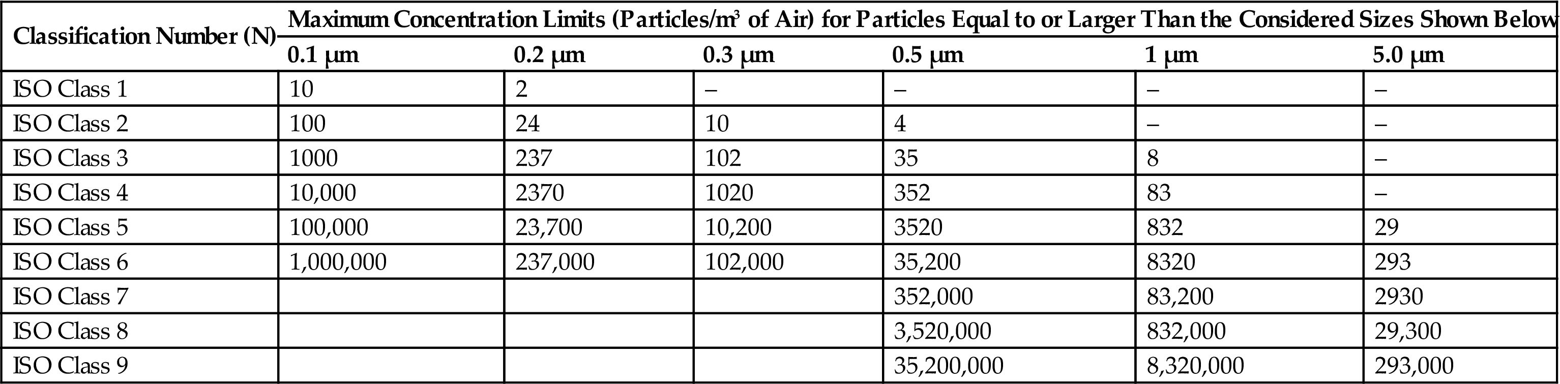
Table 3.6
Comparison of Different Airborne Particulate Classification Systems for Clean Areas [32–36]
| WHO (GMP) | United States (209 E) | United States (Customary) | ISO/TC (209) | EEC (GMP) |
| Grade A | M 3.5 | Class 100 | ISO 5 | Grade A |
| Grade B | M 3.5 | Class 100 | ISO 5 | Grade B |
| Grade C | M 5.5 | Class 10,000 | ISO 7 | Grade C |
| Grade D | M 6.5 | Class 100,000 | ISO 8 | Grade D |
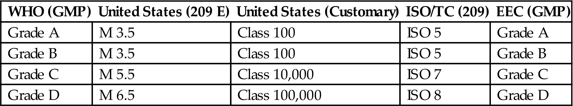
ISO/TC, ISO Technical Committee; EEC, European Economic Community.
5.4 Cleanroom Separation/Segregation
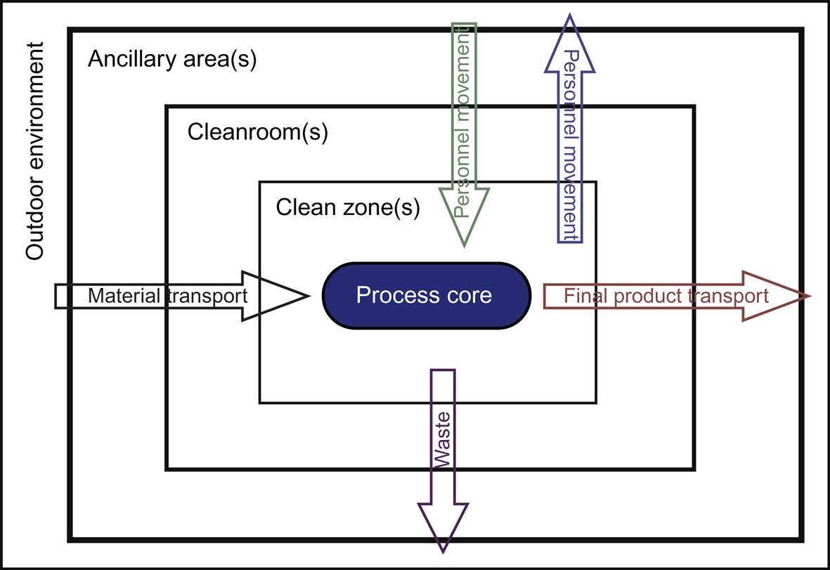
Airborne particles are generated during human activity. The amount of particles floating in the air is of great concern as it is the primary source for contamination. Adequate separation of different cleanrooms via segregation can prevent contamination. To maintain the clean area separation, a filtered air supply should be maintained at proper airflow from areas of higher cleanliness to adjacent less clean areas. Airflow pattern can be classified as unidirectional, nonunidirectional, and mixed airflow. Positive pressure differential of 10–15 Pa should be maintained between adjacent cleanrooms of different classifications. The area of the cleanroom should be kept at a minimum; if larger space is required, it should be divided into several zones or rooms, with or without physical barriers. The critical workstations should be away from entries and exits; otherwise, they may create contamination. Both personnel and materials should enter through airlocks. Airlocks or transfer hatches are normally installed to maintain pressure differential and integrity of the controlled space during entry or exit. Barriers are installed to demarcate the passage of material within an airlock system, together with appropriate decontamination devices and procedures. Air flows from top to bottom and when it returns, it should sweep clean and remove any contamination present in the cleanroom by providing appropriate air changes. Personnel moving between various zones/areas of different cleanliness levels need to change garments (depending on the cleanliness requirements of the zone) to maintain the cleanliness of the area and then enter into the clean area [37–43]. Unidirectional airflow pattern and the shell type of cleanroom segregation for prevention of contamination are shown in Figs. 3.3 and 3.4, respectively.
Three different cleanroom segregation concepts are utilized to maintain the cleanroom/zone in the pharmaceutical manufacturing premises.
1. Differential pressure concept. This concept is primarily used when ventilated rooms with different classifications are separated by a door or small opening. A low pressure differential between the cleanrooms can effectively separate the rooms by using low turbulence displacement airflow at airflow velocity greater than 0.2 m/s from the cleaner zones to the less clean zones.
2. Displacement airflow concept. This is used for separating adjacent cleanroom zones with different classifications by a pressure differential in the range of 5–20 Pa. In the displacement airflow concept, the airflow pattern may be used alone or in combination with other contamination-control techniques. The airflow should balance the quantitative inflow/outflow, so that an appropriate quantity of air can be maintained in the area.
3. Physical barrier concept. This is used in isolator technology by using an impervious barrier to prevent contamination transfer to a clean zone from a less clean zone [36,37].
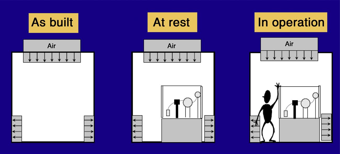
Schematic diagrams of a cleanroom as built, at rest, and in operation are shown in Fig. 3.5.
5.5 Personnel Training
About 95% of contamination comes from personnel, so to maintain the environment as a cleanroom, controlling the number of personnel movements is of utmost importance. The body itself occupies around 1% or more of the human genome, which consists of retroviral sequences and microbes in the body [36,44]. Microorganisms are part of the normal flora of the human skin and body. The human skin has either commensal or transient Gram-positive microorganisms and environment fungi, commonly Staphylococcus aureus, Staphylococcus epidermidis, Staphylococcus capitis, Staphylococcus hominis, Micrococcus species, Bacillus species, and Candida species. The human organs like eyes, ears, and human mucus fluids have Gram-negative microorganisms, which can arise on rare occasions directly from the operator and include Pseudomonas aeruginosa, and Escherichia coli. Most clinical samples originate from human fluids or tissues, which are rich in nutrients and exhibit temperatures of 35–37°C. The primary source of contamination has been found to be from personnel who shed and spread microorganisms [45–47]. Microbiological sampling of personnel includes contact plate samples of:
7. left hand glove fingers [36].
Points to remember about personnel training include:
1. the routine training of personnel who work in a controlled environment is of special importance;
2. both the operator and personnel who are working in the controlled environment also have the responsibility for monitoring, equipment maintenance, engineering, washing, and preparation;
3. a formal personnel training program related to all activities in each cleanroom and the training program should be documented;
4. the personnel training program includes subjects like basic microbiology, GMP principles, hygiene (disinfection and sanitization), aseptic connections, alert and action limits, and gowning procedures;
5. awareness of the sources of contamination and the associated risks in the cleanroom;
6. periodic process simulation tests are required to validate the training of the personnel engaged in controlled environmental conditions;
7. assessment of the competence of individuals who underwent the training program;
8. regular retraining should be provided for personnel responsible for equipment maintenance, washing, and preparation [5–12].
5.6 Sanitation and Personal Hygiene
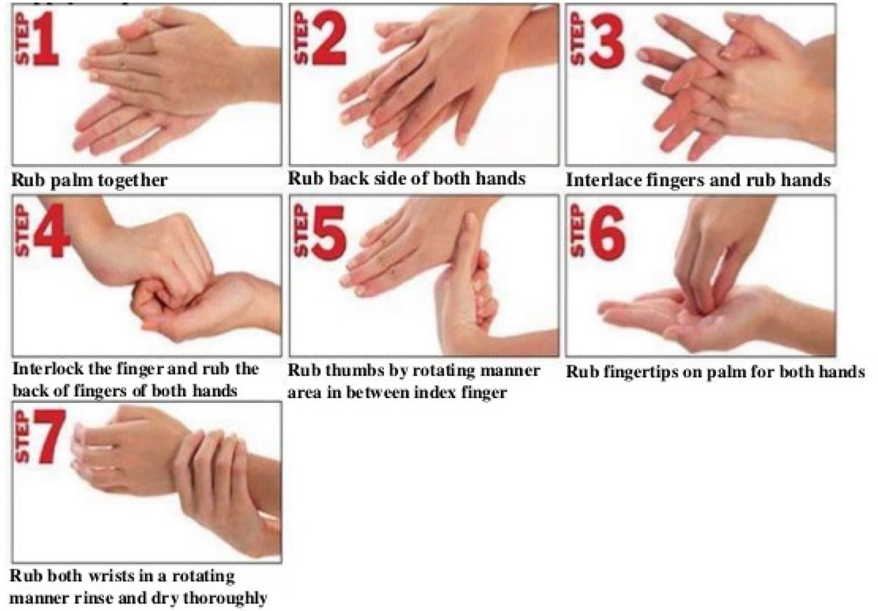
A high level of sanitation and personal hygiene needs to be practiced to avoid contamination of products during manufacturing. Practicing personal hygiene protects the personnel, premises, equipment, materials, containers, closures, and drug products from each other. Premises should be free from rodents, birds, insects, and other vermin. Various disinfectants are used in appropriate dilution to clean the premises and facilities to provide good sanitation and this cleaning should be documented. It is envisaged that personnel employed in handling pharmaceutical products exercise a high degree of personal hygiene and cleanliness and should have received appropriate training for this purpose. To maintain good hand sanitation, personnel should wash their hands before starting the work and after completion of work and as often as the job requires [1,5–12,18,36,48,49]. The steps for effective washing of hands are shown in Fig. 3.6.
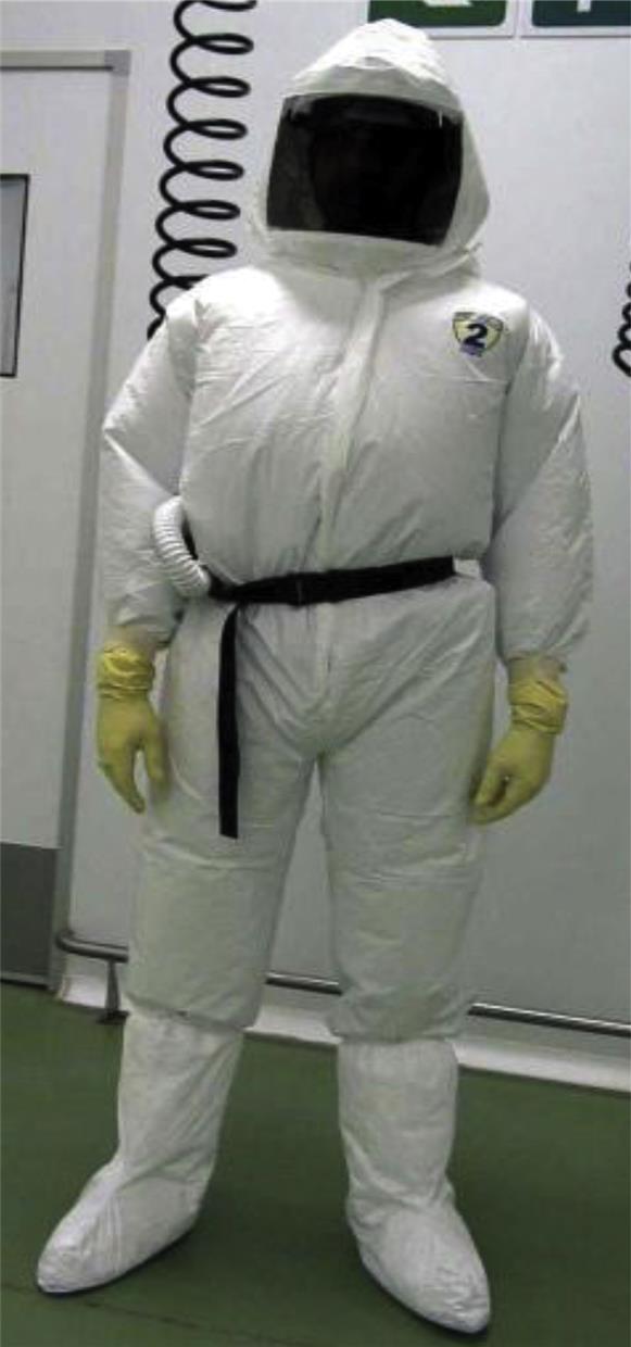
5.7 Gowning/Change Room Control and Configuration
Personnel gowning can prevent shedding of human microbial flora into products, surfaces, air, and samples. A special airlock facility should be provided for the personnel entry and exit in the changing/gowning room. The change room should have sufficient space for donning and removing the specialized garments, along with a disinfection facility for washing while exiting from the change room. Special control devices like air showers and shoe cleaners should be provided while entering the cleanroom.
To maintain the clean zone in the premises, three functional zones are present in the changing rooms that are separated by physical barrier. The various zones in the change room are (Fig. 3.7):
1. Gowning/changing room entry. This can be accessed from ancillary areas, either directly or via an airlock appropriate for removal, storage, disposal, and/or redonning of garments that are not permitted within the cleanroom.
2. Transition zone. In this zone, appropriate garments dedicated to the cleanroom are stored, donned, or removed.
3. The inspection/access zone. This zone provides access to the cleanroom, either directly or via an airlock only after the complete gowning process is accomplished. A full length mirror may be provided to check effective fit of the garments by personnel [37,48].
6 Validation of HVAC System
Cross contamination can be prevented by using an effective HVAC system on the premises. Air changes in pharmaceutical cleanrooms play an important role in maintaining cleanroom quality.
Validation of the HVAC system includes [22,24,47,49–52]:
2. monitoring airflow velocity and changes per hour
6. filter integrity test (DOP (dioctyl phthalate)/PAO (polyalphaolefin) test)
7. pressure differential control
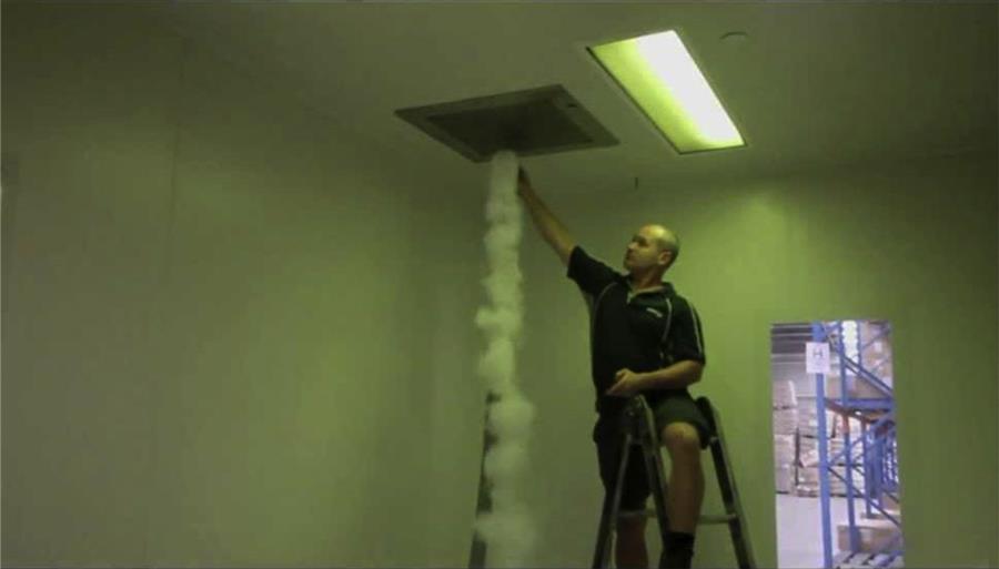
6.1 Airflow Pattern
For the evaluation of airflow pattern, a titanium tetrachloride stick is taken and burnt; the burning stick produces smoke through a nozzle point and it is placed in front of the HEPA filter commonly at the ceiling. Smoke will get distributed in the room based on its flow pattern, either unidirectional or turbulent, toward the work surfaces and equipment. The airflow pattern should be uniform. The smoke distribution is recorded and a chart diagram is made of the airflow for each room. In general, ISO Class 5 is used to verify the airflow pattern. A schematic diagram of unidirectional airflow pattern test is shown in Fig. 3.8.
6.2 Airflow Velocity and Changes per Hour
1. For this test, the area of the HVAC system is scanned by using an anemometer probe 15.2 cm (6 in.) from the filter face.
2. The area of the HEPA filter is divided into four equal hypothetical grids.
3. The air velocity is measured at the center of each grid and at the junction of the dividing lines.
4. Calculate the average velocity V as follows:
(5.2)
where V is in ft/min, and V1, V2, V3, and V4 are the velocities for the observation at different points.
5. Measure the dimension (in ft) of each air inlet and record it.
6. Calculate the area of each air inlet as length (l) and width (w).
(5.3)
7. Calculate the total air volume (T in ft3/min).
(5.4)
8. Calculate the room total volume by multiplying the length, breadth, and width of the room.
9. The total number of air changes per hour is obtained by dividing the total air change by the volume of the room.
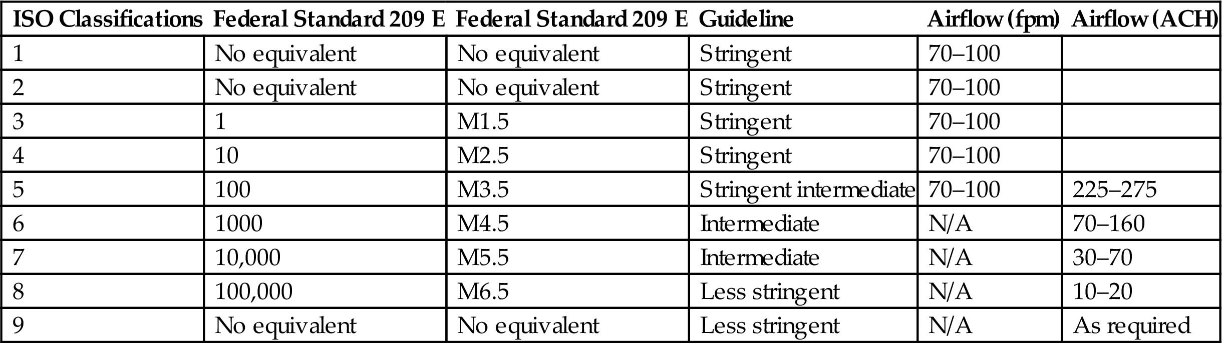
The Institute of Environmental Sciences and Technology Recommended Practice 12 (IEST-CC-RP.012.1) [53] includes a table with a range of recommended airflow rates for each cleanliness class, as does the more recently published ISO 14644-1, Part Four [39]. Recommended airflow rates and airflow changes per hour for cleanrooms are shown in Table 3.7.
Table 3.7
Recommended Airflow Rates and Airflow Changes per Hour for Cleanrooms [39]
| ISO Classifications | Federal Standard 209 E | Federal Standard 209 E | Guideline | Airflow (fpm) | Airflow (ACH) |
| 1 | No equivalent | No equivalent | Stringent | 70–100 | |
| 2 | No equivalent | No equivalent | Stringent | 70–100 | |
| 3 | 1 | M1.5 | Stringent | 70–100 | |
| 4 | 10 | M2.5 | Stringent | 70–100 | |
| 5 | 100 | M3.5 | Stringent intermediate | 70–100 | 225–275 |
| 6 | 1000 | M4.5 | Intermediate | N/A | 70–160 |
| 7 | 10,000 | M5.5 | Intermediate | N/A | 30–70 |
| 8 | 100,000 | M6.5 | Less stringent | N/A | 10–20 |
| 9 | No equivalent | No equivalent | Less stringent | N/A | As required |
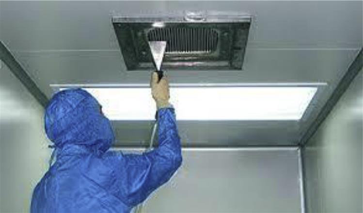
6.3 Filter Leak Test
Filter leak test is performed on the HEPA filter by using a velometer. The velometer is placed in front of the air-handling unit system and the air velocity is checked in all corners of the HEPA filter (Fig. 3.9). The observed air velocity should be within the acceptance limit of the HEPA filter; in case it exceeds the acceptance limit, the gas cut in the HEPA filter is replaced with a new one to ensure the velocity is within the range.
6.4 Particle Count Test
For performing the particle count test, the particle count is taken in the room at rest before performing any work or nonwork operations. This is followed by particle counts during process operations in the cleanroom. Record the data in the format and determine whether the particle count limits are within the acceptance limit of the cleanroom specification. For routine testing, the total sample volume should not be less than 1 m3 for grade A and B areas and preferably also for grade C areas. The minimum number of sampling points is calculated based on the area of the cleanroom in square meters. The number of sampling points is derived from the following equation:
(5.5)
where NL is the minimum number of sampling locations (rounded to a whole number); A is the area of the cleanroom or clean zone in square meters.
The maximum permitted numbers of particles/m3 for different cleanliness grades for various standards and guidelines are given in Tables 3.8–3.10.
Table 3.8
EEC and PIC/S Airborne Particulate Limits
| Grade | At Rest | In Operation | ||
| 0.5 µm | 5 µm | 0.5 µm | 5 µm | |
| A | 3500 | 1 | 3500 | 1 |
| B | 3500 | 1 | 350,000 | 2000 |
| C | 350,000 | 2000 | 3,500,000 | 20,000 |
| D | 3,500,000 | 20,000 | Not defined | Not defined |
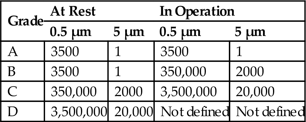
Table 3.9
WHO Airborne Particulate Limits
| Grade | At Rest | In Operation | ||
| 0.5–5.0 µm | >5.0 µm | 0.5–5.0 µm | >5.0 µm | |
| A | 3500 | 0 | 3500 | 0 |
| B | 3500 | 0 | 350,000 | 2000 |
| C | 350,000 | 2000 | 3,500,000 | 20,000 |
| D | 3,500,000 | 20,000 | Not defined | Not defined |
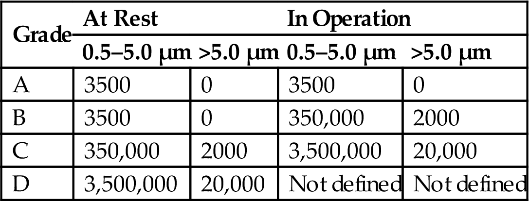
Table 3.10
Maximum Permitted Number of Particles per m3 for Each Grade
| Guideline | Grade | At Rest | In Operation | ||
| 0.5 µm | 5 µm | 0.5 µm | 5 µm | ||
| EU | A/Ba | 3520 | 20/29 | 3520 | 20 |
| ISO | 5 | 3520 | 29 | 3520 | 29 |
| FDA | 100 | – | – | 3520 | – |
| EU | – | – | – | – | – |
| ISO | 5 | 35,200 | 293 | 35,200 | 293 |
| FDA | 1000 | – | – | 35,200 | – |
| EU | Bb | – | – | 352,000 | 2900 |
| ISO | 7 | 352,000 | 2930 | 352,000 | 2930 |
| FDA | 10,000 | – | – | 352,000 | – |
| EU | C | 352,000 | 2900 | 3,520,000 | 29,000 |
| ISO | 8 | 3,520,000 | 29,300 | 3,520,000 | 29,300 |
| FDA | 100,000 | – | – | 3520000 | – |
| EU | D | 3,520,000 | 29,000 | Not defined | Not defined |
| ISO | 9 | 35,200,000 | 293,000 | 35,200,000 | 293,000 |
| FDA | – | – | – | – | – |
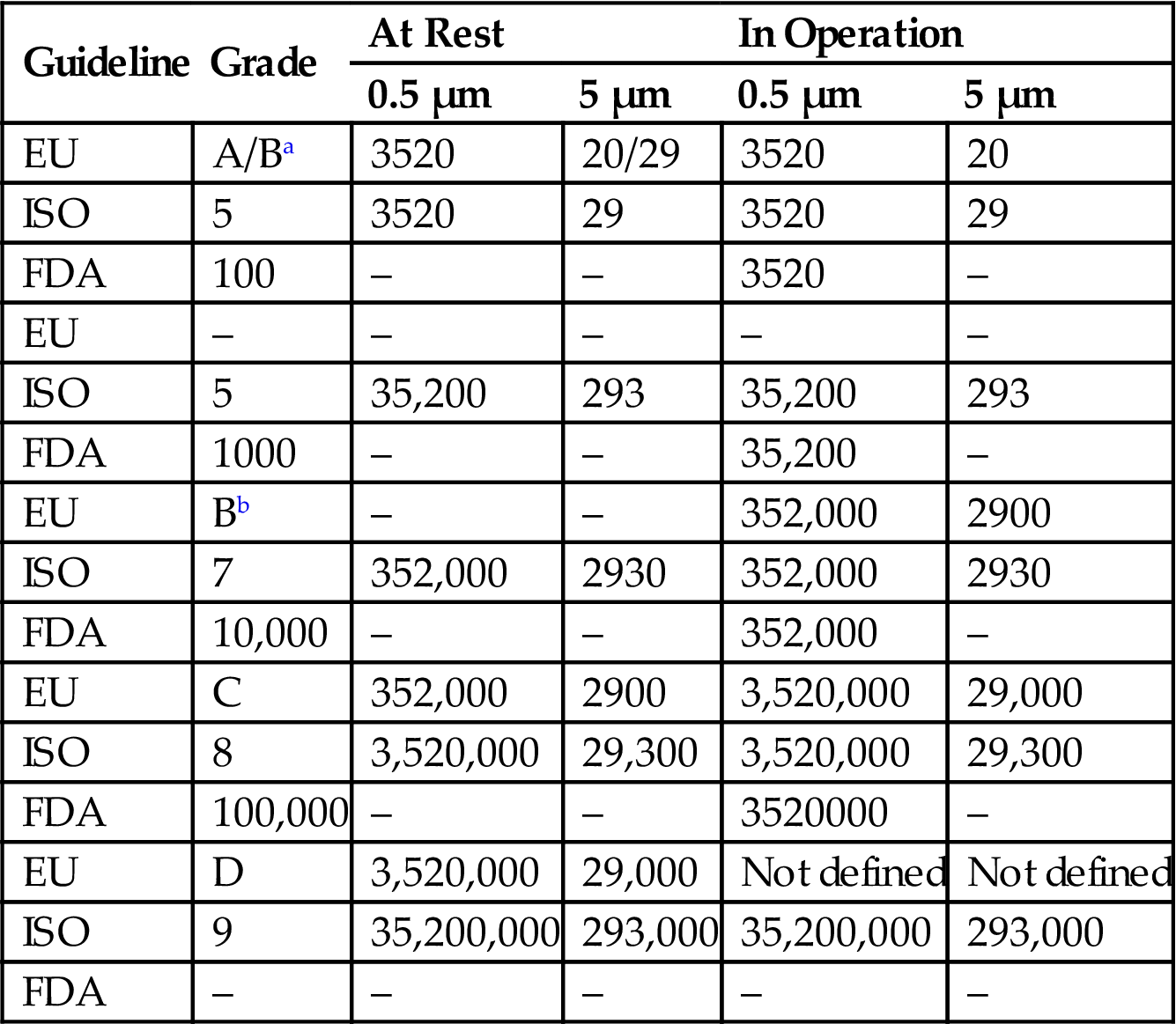
aRefers to grade B at rest.
bRefers to grade B in operation.
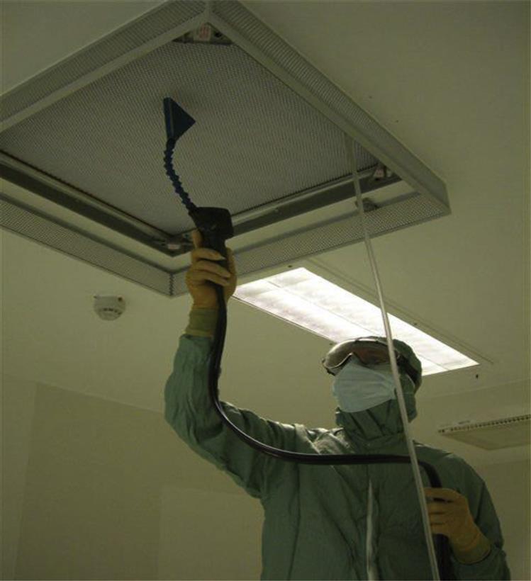
6.5 Viable Monitoring
Air is a major source of microbial contamination. Viable monitoring is performed by exposing the suitable nutrient medium for the incubation of microorganisms. Air sampling can be performed using different methods. The various methods are given in Sections 6.5.1–6.5.3.
6.5.1 Active Air Sampling
The air sampler is disinfected with a suitable disinfectant and placed in the center approximately 1 m above the floor of cleanroom. Using the Reuter centrifugal sampler 1000 L of air is sampled and introduced into the agar strips, incubated for 48 hours at 30–35°C, and then for 72 hours at 20–25°C. After the incubation period, count the colonies and record according to the format.
6.5.2 Passive Air Sampling
Tryptone soy agar medium in a 9-cm Petri dish (2 dishes) is used for passive air sampling. Air sampling is performed according to the 1/1/1 scheme (for 1 hour, at a height of 1 m at least 1 m from walls or any obstacle) for each round, and in room areas where there is little air movement (i.e., “dead spaces”), in room areas where airflows are excessively turbulent, and in areas within the cleanroom where there has been personnel activity or where specific operations were carried out. Incubate the petri dishes for 48 hours at 30–35°C and then for 72 hours at 20–25°C. After the incubation period, count the colonies and record according to the format.
6.5.3 Surface Monitoring
Contact plate method
Replicate organism detection and counting plates containing tryptone soy agar are used for surface sampling. The tryptone soy agar in contact plates is mixed with polysorbate 80 and lecithin, which inactivate many residual disinfectants. The contact plate containing tryptone soy agar is pressed onto the surface area to be tested. Any microorganism present on the surface will be transferred to the contact plate. The sampled surface area is cleaned with 70% isopropyl alcohol. Incubate the contact plate for 48 hours at 30–35°C and then for 72 hours at 20–25°C. After the incubation period, count the colonies and record according to the format.
Swabbing method
A sterile swab from a sterile tube moistened with phosphate buffer saline solution at pH 7.2 is used for swab sampling of the surface. The sterile swab is swabbed over a defined surface area by moving it back and forth across the surface. After sampling, the swab is returned to its prelabeled sampling tube containing an appropriate amount of liquid medium.
The maximum permitted numbers of microorganisms for various guidelines are given in Tables 3.11–3.13.
Table 3.11
Recommended Limits for Microbial Contamination by EU and FDA Guidelines
| Guideline | Grade | Air Sample | Settling Plate Diameter 90 mm (CFU/4 h) | Contact Plate Diameter 55 mm (CFU/Plate) | Glove Point 5 Fingers |
| EU | A | <1 | <1 | <1 | <1 |
| FDA | 100 | 1a | 1a | – | – |
| EU | – | – | – | – | – |
| FDA | 1000 | 7 | 3 | – | – |
| EU | Bb | 10 | 5 | 5 | 5 |
| FDA | 10,000 | 10 | 5 | – | – |
| EU | C | 100 | 50 | 25 | – |
| FDA | 100,000 | 100 | 50 | – | – |
| EU | D | 200 | 100 | 50 | – |
| FDA | – | – | – | – | – |
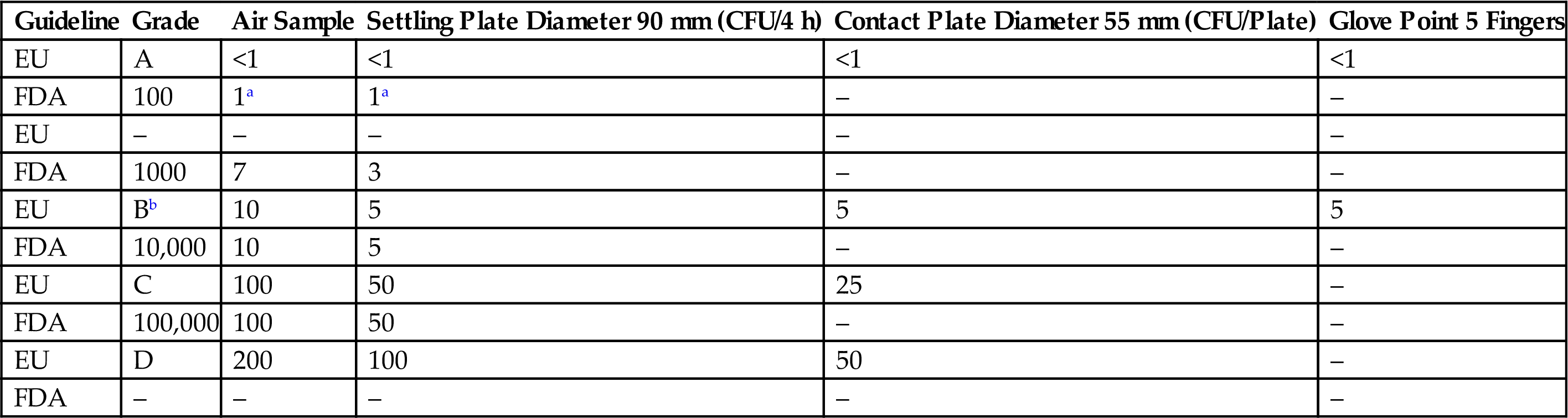
aNo microbial contamination is expected on samples from Class 100 cleanroom.
bThe comparison between EU and FDA guidelines was performed assuming in-operation values.
Table 3.12
Recommended Limits for Microbial Contamination by PIC/S Guideline
| Grade | Recommended Limits for Microbial Contamination | |||
| Air Sample (CFU/m3) | Settling Plate Action Levels (Diam. 90 mm) (CFU/4 h) | Contact Plats (Diam. 55 mm) (CFU/Plate) | Glove Point 5 Fingers (CFU/Glove) | |
| A | <1 | <1 | <1 | <1 |
| B | 10 | 5 | 5 | 5 |
| C | 100 | 50 | 25 | – |
| D | 200 | 100 | 50 | – |
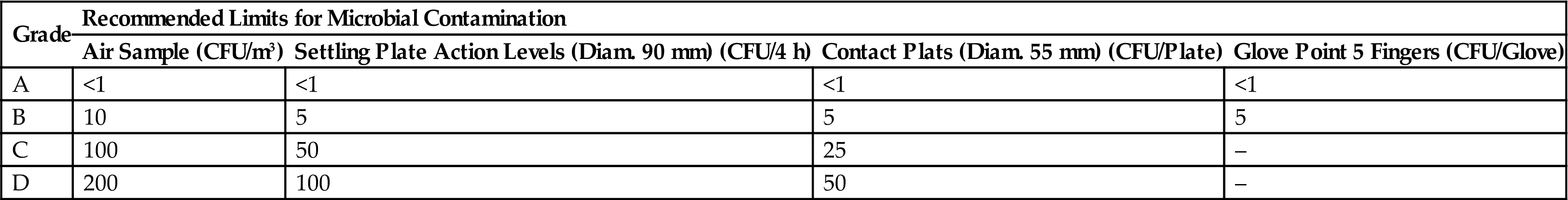
Table 3.13
Recommended Limits for Microbial Contamination by WHO Guideline
| Grade | Recommended Limits for Microbial Contamination | |||
| Air Sample (CFU/m3) | Settling Plate Action Levels (Diam. 90 mm) (CFU/4 h) | Contact Plats (Diam. 55 mm) (CFU/Plate) | Glove Point 5 Fingers (CFU/Glove) | |
| A | <3 | <3 | <3 | <3 |
| B | 10 | 5 | 5 | 5 |
| C | 100 | 50 | 25 | – |
| D | 200 | 100 | 50 | – |

6.6 Filter Integrity Test (DOP/PAO Test)
Earlier filter integrity tests were performed using DOP, which is a liquid chemical that produces mono- or polydispersed test aerosols of submicron particles. Due to its carcinogenicity it has been replaced by PAO. PAO aerosol is generated by subjecting the PAO to 138 kPa in an aerosol generator, and supplying the generated aerosol to the supply duct of the air handling system. Scanning is performed by using a handheld photometer (scanning probe) after ensuring that 100% upstream concentration is achieved in the terminal HEPA filter. The end of the probe should be held within 1 in of the exhaust and scanned at a traverse rate of no more than 10 ft/min. The display indicates the percent of leakage through or around the filter or exhaust canister. Test all the HEPA filters as per the above procedure and record the observed results according to the format. A schematic diagram for performing the filter integrity test is shown in Fig. 3.10.
6.7 Pressure Difference
Pressure difference between the rooms is measured using a manometer. Attach the manometer to the wall of all the involved rooms. Observe the pressure difference between the entire and the external areas, and between individual rooms. Generally the pressure difference is kept between 0.67 and 2.7 kPa (5 and 20 mm Hg) pressure. Record the observed results according to the format.
6.8 Recovery Test
The recovery of temperature and humidity is checked by this test. For this test, the humidity and temperature are checked at the off position of the HVAC system. Then the humidity is increased to 75% and temperature to 40°C and again the temperature and humidity are measured after switching on the HVAC system, and the time required to stabilize the temperature and humidity is noted.
A hygrometer is used to measure the humidity. The HVAC system is turned off and the humidity of the area is measured. If the humidity is within specification, spray the hot water and increase the humidity up to 75%. Operate the HVAC system and calculate the time taken to stabilize the humidity within the specification limit. Record the observed time results according to the format.
For the recovery test, the hot air blower is used to increase the temperature. Increase the temperature of the area to 40°C. Operate the HVAC system and calculate the time taken to stabilize the temperature within the specification limit. Record the observed time results according to the format.
6.9 Temperature and Humidity Uniformity Test
Temperature. Uniformity of temperature in the clean area is measured using a calibrated thermometer. Place the calibrated thermometer in different locations in the clean area. Operate the HVAC system and calculate the time taken to stabilize the temperature within the specification limit. Record the observed time results according to the format.
Humidity. Uniformity of humidity in the clean area is measured with a calibrated hygrometer. Place the calibrated hygrometer in different locations in the clean area. Operate the HVAC system and calculate the time taken to stabilize the humidity within the specification limit. Record the observed time results according to the format.
6.10 Fresh Air Determination
Stabilize the air pressure in the room. The fresh air intake is determined by observing the air intake at the inlet of the fresh air dumper in the room. Calculate the total air changes in the room. The fresh intake air is divided by the total air changes in the room and multiplied by 100 to determine the percent of fresh air intake in each cycle by the HVAC system in the specific tested room. Record the observed results according to the format.
6.11 Acceptance Criteria for HVAC System
1. HEPA filters must be 99.99% efficient when tested with PAO aerosols (0.3 µm).
2. All the terminal HEPA filters must have velocity measurements within ±30% of the average filter velocity.
3. The average face velocity of terminal HEPA filters in a Class 100 (ISO Class 5) room with laminar flow is 90 ft/min±20%, with no points below 75 ft/min or above 105 ft/min.
4. All room supply, exhaust, and return airflow rates must be within ±10% of design flow rates.
5. Directional airflow must be consistent with design drawings.
6. Each room must maintain the designed temperature and humidity range for three consecutive days.
7. Airflow in a Class 100 (ISO Class 5) area must be nonturbulent and unidirectional as demonstrated by airflow pattern studies.
8. All the classified rooms must meet their particulate classification as per the specification.
7 Summary
Quality is always an imperative prerequisite for any product. Drug substances and drug products are used by the public for treating various diseases. Therefore, the manufacturer must manufacture the drug substances and drug products with the highest standards of quality, purity, safety, and strength to produce the desired therapeutic effect.
The quality, purity, safety, and strength of the product are ensured by various factors such as careful selection of quality materials/components, product and process design, control of processes, in-process control, and end-product testing. End product testing does not ensure the quality of the product; rather, the quality of the product can be built in, in each properly designed system process. GMP as envisaged in the guidelines can be practiced with relative ease when one covers the basics with the right intention. Various GMP guidelines are framed with respect to their region, but the basic concepts of all the GMP guidelines are similar to each other. GMP is a system that encompasses the complete manufacturing setup, ranging from entry into the area, air-handling systems, hygiene, sanitation, garments and qualification of the personnel, HVAC systems, positive pressure inside the production area, and the planned infrastructure, and is executed at the beginning stage itself. GMP needs to be followed by the manufacturer during the manufacturing process to ensure the highest standards of quality, purity, and safety with the desired efficacy.
The HVAC system is a fundamental component of the pharmaceutical manufacturing facility. Air handling units are components of a mechanical system that is used to condition and circulate air as part of the HVAC system. An air handler typically consists of a fan, heating coils, cooling coils, a filter section, sound attenuators, dampers, actuators, and controls, depending on the particular design. Operating an HVAC system at optimum efficiency is a critical task. HVAC helps to enhance and maintain the quality of drug substance and drug products by maintaining a suitable temperature for continuous flow of air, which ultimately prevents cross-contamination, and for accumulation of air to ensure cooling of air in the premises.
Cleanrooms are normally designed as functional units in the manufacturing premises for specific purposes. Adequate separation of cleanrooms for various operations is an important part for prevention of contamination. Regular environmental monitoring in different locations in the pharmaceutical premises has direct impact on the prevention of contamination of the pharmaceutical products. Maintaining the quality of air and higher cleanliness in the cleanroom can be achieved by proper airflow and a positive pressure differential relative to an adjacent less clean room. A well-designed cleanroom is constructed with materials that allow for ease of cleaning, sanitizing, and prevention of contamination.
However, in the manufacturing premises GMP guidelines need to be followed constantly and the environmental conditions in the critical processing area need to be monitored continuously to ensure that the manufactured products have the highest standards of quality, purity, safety, and strength to meet the regulatory requirements.