
![]()
Introduction to Arduino
In this chapter, we’ll be introduced to the Arduino prototyping platform. As with the previous chapter, if you’re already using Arduino, and you’re programming it yourself, feel free to skip this chapter. Mind you, that apart from the Arduino language itself, we’ll also focus on its serial communication capabilities, in combination with Pd. This means that we’ll be using both ways of serial communication (Serial.println() and Serial.write()), and we’ll analyze the way they work, their differences, as well as their advantages and disadvantages compared to one another.
By the end of this chapter, you’ll be able to
- Write simple programs for the Arduino for your physical modeling projects
- Use looping mechanisms to facilitate your coding
- Understand the way serial communication is achieved, and which way to choose when
- Use the Arduino in combination with Pd and take advantage of each platforms capabilities
Arduino Jump Start
The Arduino board is a microcontroller that takes input from the physical world, using various sensors, and uses it in computer programs. It can be used as a stand-alone application, but also in combination with a computer to realize things that are more complex. The communication between the physical world and the computer goes also the other way round. The Arduino can give input to the physical world, by using LEDs, lights, motors, solenoids, and so forth. The Arduino is also a programming environment and a programming language. The language is built on C++, but has a great set of its own functions. The third element that comprises the Arduino in its entirety is its community. It has a large community of users, makers, developers, enthusiasts, that share work and projects between them. It is very similar to the Pd community, as they are both open source and widely used.
In contrast to Pd, Arduino is a textual programming language, but a very intuitive one. It also runs on all three major operating systems, like Pd, and its software is for free. Being open source, its hardware is open as well. All the schematics and circuit designs are open for anyone to use. So, if you have the facilities, you can build one yourself. That is a difficult task though, and you are encouraged to buy an original Arduino from your local reseller, or from their web site.
What makes the Arduino so special is not that it’s a microcontroller that uses sensors, or that it can communicate with a computer to give input from or to the physical world, but the fact that it has been packaged with its software in such a way that it makes physical computing (the communication between the computer and the physical world) much easier than ever before. Microcontrollers are said to be a very difficult field in programming, but the Arduino is very simple to program. Also, the way it is build, facilitates prototyping to a great extent, where you can plug in a few sensors and start using them in a matter of a few minutes. The Arduino has actually revolutionized the way we use microcontrollers and the contributed in the expansion of the maker communities worldwide.
To follow this chapter and the rest of this book, you’ll need to buy an Arduino board, and download the software. Go to its web site at www.arduino.cc, get the Arduino IDE (Integrated Development Environment, the Arduino software), and find your local distributor. At the time of writing (August 2015), there are issues within the Arduino team. This means that if you buy an Arduino outside the United States, it will be called Genuino. The name is the only thing that changes, the rest remain the same. This change applies for a few boards, the UNO, the MICRO, and the MEGA. The NANO and the PRO MINI, shouldn’t be affected. These issue should actually be solved with the appearance of the Genuino. Still, we’ll refer to it as Arduino, and we’ll mean both boards, since they are essentially the same.
With Arduino, it is advisable to get the UNO, as it is designed for prototyping. In this chapter, this is the Arduino we’ll use. In the chapters that follow, we’ll use other types of Arduino, like the NANO and the PRO MINI, as they are much smaller, so not so good for prototyping, but perfect for being embedded in a project. Their cost is rather low, maybe the NANO is a little bit more expensive, so it shouldn’t be very difficult to get one of each. Don’t bother to buy them all yet, if you want to build a project in this book that requires another type that you don’t have, then go get one.
Along with the Arduino, we’ll be using some peripherals, like LEDs, switches, potentiometers, and so forth. Each project will needs its own peripherals, so you should probably get them as you go. In this chapter, we’ll use peripherals for prototyping, so instead of potentiometers, we’ll use trimmers (these are breadboard-friendly potentiometers). These prototyping peripherals will be helpful for many more projects, as when building an electronics project, we first prototype and them start building.
At this point, I should mention that there is a rather easy way to use the Arduino, if you’re already using Pd. That is the Firmata library, which lets you program the Arduino through Pd (or other programming environments). Since we’ll be using some built-in functions of the Arduino language, using Firmata here won’t really help, so we’re not going to use it at all. Instead, we’re going to write our own small programs and restrict the Arduino to the few simple things we need to use. This way we’ll get a better understanding of its language, the serial communication, and how it is combined with Pd.
Parts List
In this section, we’ll review the parts you’ll need to build all the projects of this chapter. Table 2-1 shows what each project will use. In addition to that, you’ll need some jumper wire (make sure that you get a few), a breadboard (a half size will probably do, but a full size won’t be bad, as it will prove useful for future projects too), and of course, an Arduino Uno and a USB cable.
Table 2-1. Parts List

Make sure that the push buttons you get are breadboard-friendly (also called tactile switches), as well as the potentiometers (these one are also called trimmers). The resistors are counted in ohms, so a 10KΩ resistor is 10 kiloohms, and a 220Ω is a 220-ohm resistor.
Before we start looking at Arduino code, make sure you have yourself an Arduino, preferably the UNO, so you can realize all the programs in this chapter. Figure 2-1 shows an Arduino UNO. The chip in the middle of the board is the actual microcontroller, an Atmel ATMEGA 328. We can also see a USB socket that we’ll use to connect it to our computer. There’s also a power JACK socket on the same side with the USB, but since we’ll use the Arduino always in combination with a computer, we won’t need that, as it will be powered through the USB. On the sides, we can see a few sockets with some indications on them. These are the pins to which we’ll be attaching sensors, LEDs, and so forth. There are both analog and digital pins, for the corresponding sensors. On each project, there will be a diagram of the circuit, so it will be easy to follow.

Figure 2-1. Arduino UNO
When learning programming, usually the first task is to print “Hello, World!” to a monitor. In Pd, the first thing we did was to output a sine tone at 440 Hz (that is the usual case when learning audio programming). When learning how to program the Arduino, we usually make an LED blink. In electronics, making LEDs blink is the very basis. It is said that, if you can make an LED light up, you can do anything. So what we’ll do first in this chapter is to make an LED blink. The Arduino IDE has a sketch (this is how we refer to Arduino code) that does exactly that.
Go ahead and launch the Arduino IDE. What you’ll get at the beginning is a new sketch window, like the one in Figure 2-2. In contrast to Pd, this window is not totally empty. First of all, at the very top, it writes “sketch_aug07a | Arduino 1.6.5”. This is a default sketch name given by the IDE. “aug” stands for August (all this is written in August), “08” stands for the eighth of the month, and “a” stands for the first sketch of the day. If you reach the limit of the Latin alphabet, you’ll get a window saying, “You’ve reached the limit for auto naming of new sketches of the day. How about going for a walk instead?” and it won’t let you create a new sketch. Just restart the application and it will work again. I’m pretty sure that you won’t reach that limit unintentionally (I kept on creating new windows till I got to the end, just to see what happens). The second part of the top line is the version of the IDE you’re using.

Figure 2-2. A new sketch window
On the very bottom of the window, on the left side you can see the line in your sketch where the cursor currently is. On the right side, you see the selected Arduino board and its serial port (can’t really remember if there was any serial port when I first installed the IDE and opened a new window without having set a port yet). In the case in Figure 2-1, it’s an Arduino Uno, on port /dev/cu.usbmodem411 (this is on OS X). Later on, we’ll talk about all this in more detail.
In the window, we see a little bit of code. The first line reads void setup() {. This is a built-in function that runs once as soon as the Arduino is powered. We won’t bother with the word void for now. setup is the name of the function. When we program in C++, we can create our own functions, and we have to give them a name. Think of it a bit like an abstraction in Pd. The parenthesis are obligatory when writing a function. They are there in case the function takes arguments, and even if it takes no arguments, you must still include them. After the parenthesis, there is an opening curly bracket. When we define a function, its code is included in curly brackets, and we can see the closing bracket in line 4. Whatever is written inside these brackets is the code of the function, which will be executed when we call that function (for the setup function, as soon as the Arduino is powered). By “define,” I mean to write the code of the function. Both setup and loop are not defined by default, but are there for us to define them any way we want.
Line 2 has a comment. This is like the comments in Pd, they are there to give us information, and they don’t affect the program at all. The compiler (the compiler is the program that turns code into an executable program) will ignore all comments when it will compile the code. This is a single line comment and it must start with two forward slashes. The comment reads "put your setup code here, to run once:". This actually tells us what really happens with this function, it runs only once, when the Arduino boots.
In line 7, we read void loop() {. This is another built-in function of the Arduino language and runs immediately after the setup function, over and over again, hence its name loop. Again we have the parenthesis, since it’s a function, and the curly brackets, because it hasn’t been defined yet. Inside it, we read the comment, "put your main code here, to run repeatedly:". This is where we’ll be writing most of our code, and this will run for as long as the Arduino is powered.
The different colors for various keywords of functions and others, are there to facilitate the reading and writing of code. Most of IDEs have color highlighting for this reason. In the Arduino language, the blueish color of void is the color for data types (like integer, float, byte, etc.; you’ll see them later on). The color of setup and loop is the color for these two functions and all control structures (if, for, while, and others). All comments are grey and all defined functions (not setup and loop) are orange. We’ll see all this as we read further on.
Now go to File ![]() Examples
Examples ![]() 01.Basics, and click Blink. This should open a new window with the code in Listing 2-1 in it.
01.Basics, and click Blink. This should open a new window with the code in Listing 2-1 in it.
This is the first Arduino sketch we’ll upload to our board. To get a grasp of how things work with the Arduino, we’ll go through its code in detail, step by step. The code here has all lines numbered for convenience, but the Arduino IDE doesn’t show these line numbers, only the number of the line where the cursor is, at the bottom of the window. The first fourteen lines of code are a multiline comment. To make a multiline comment in Arduino, start it with a forward slash and an asterisk, and end it with an asterisk and a forward slash. Whatever you write in between will be ignored by the compiler. This specific comment tells us what this sketch does, gives some information about the integrated LED on the Arduino and some other meta-data.
After the multiline comment, we have a single line comment giving information about when the setup function runs, and then we have the actual setup function. In line 19, we have a comment: "initialize digital pin 13 as an output". Indeed, line 20 does exactly that. Since we’ll use an LED and we will be turning it on and off, the pin we’ll use for this is a digital pin, because it has two possible states only, on or off (same as 1 or 0). Also, this pin will output voltage to the LED, so it must be an output pin. Digital pins can be either input or output, whereas analog pins are only input. This line also shows how intuitive the Arduino language is. The function to set a pin either as input or output—in other words, to set the mode of the pin—is called pinMode, and you can tell that it’s a function by the parenthesis after its name. This function is part of the core of the Arduino language and has already been defined. That’s why it has no curly brackets, like setup and loop, and you can’t write code in it, but only use it as is. This is the first predefined function we encounter and we can see that it is color highlighted in orange, as mentioned earlier. pinMode takes two arguments, the pin to set the mode to, and the mode to set to that pin. The pin we’ll use is pin 13, because that’s the pin Arduino Uno has an integrated LED on. For the second argument, we use a keyword of the Arduino language, OUTPUT. This keyword (the language is case sensitive, so output won’t work) tells pinMode to set the specified pin as an output. Mind the semicolon (;) at the end of the line. pinMode is a predefined function, so we must put a semicolon whenever we call it. All executable lines of code in C++ end with a semicolon. This tells the compiler that this is the end of the line and that this line must be executed. Functions that are being defined (like the setup and loop) don’t take a semicolon, but all code written inside them does.
Our setup function consists of one line of code only (plus a single line comment). Line 21 closes the brackets of the setup function and we move on to the loop function. Notice how all code within setup is indented. The same happens with loop too. All functions and control structures have their code indented, for readability. You’ll see that it is a very helpful feature. In the Arduino IDE, when you open a curly bracket and hit enter, the code automatically gets indented.
In our loop function, we can see four lines of code, where we call two functions, two times each. Both these functions are predefined, like pinMode. The first one, on line 25 is the digitalWrite function. As its name states, this function writes a value to a digital pin. Like pinMode, this one also takes two arguments, the pin to write a value to, and the value to write to that pin. In this case, we want to turn the LED on pin 13 on. Again, we provide the number 13 for the pin number. On can be indicated by the keyword HIGH. HIGH stands for high voltage. Sending voltage to that pin, will turn the LED on. Mind the semicolon after the function call.
We can see that after the semicolon there is a single line comment. The comments we’ve seen so far start at the beginning of the line, but single line comments can start at any point of a line. The compiler will compile the line up to the point of the two forward slashes, after which point it will ignore everything. This comment tells us what this line of code does, which is to "turn the LED on (HIGH is the voltage level)".
The next line reads delay(1000);. delay is another built-in, predefined function. What it does is delay the rest of the program by a specified amount of time, which we set via its argument (delay takes one argument only), in milliseconds. This line of code will delay the rest of the program for 1000 milliseconds, or for 1 second. After we call that function, we put a semicolon to let the compiler know we’re done with that line, and then there is a comment saying that we’ll wait for a second.
After delay, we call digitalWrite again, but this time we set the pin LOW, meaning we drop the voltage low, so the LED will turn off. The comment after the semicolon explains that as well. Lastly, we delay our program for another second by calling delay(1000); as we did before. And this concludes our first Arduino sketch. In line 29, we put the closing bracket for the loop function (no semicolon here as we are defining the function).
What you might have noticed is that in textual programming the code is being executed line by line, the same way we read it. In visual programming, we can see the data flow by the connections between the objects, in textual programming the data flow is being defined by the position of each line of code. Since I have explained the Blink sketch, let’s upload the code to our Arduino board, to see it in action. Plug in your Arduino and go to Tools ![]() Board: and you’ll get the menu shown in Figure 2-3.
Board: and you’ll get the menu shown in Figure 2-3.
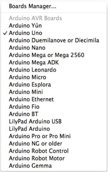
Figure 2-3. The Boards menu on the Arduino IDE
You can see that there are many different boards supported by the IDE. If the Uno is not already selected, go ahead and click it (if you’re using another board, click that). The menu will close, but the board will have been selected. Once you’ve done that, you must select your port. Go to Tools ![]() Port and a menu with all available ports will open. The Arduino port should have an indication like the one in Figure 2-4. On OS X the port is /dev/cu.usbmodemx,1 on Linux it’s /dev/ttyACMx, and on Windows it’s COMx, where x is a number. Select your port (again, the menu will close, but the port will have been selected) and you’re ready to upload the sketch to your board. On the top of the sketch window, there are a few icons, as shown in Figure 2-5. The icon with the arrow inside it is the Upload button. Click it and the IDE should start uploading the sketch to the board. Before it uploads the code to the board, it will first compile it, and on the bottom of the sketch window, you’ll see the compilation process progress, shown in Figure 2-6. When the code has been compiled, the IDE will start uploading it to the board, and now you’ll see the upload progress, shown in Figure 2-7.
Port and a menu with all available ports will open. The Arduino port should have an indication like the one in Figure 2-4. On OS X the port is /dev/cu.usbmodemx,1 on Linux it’s /dev/ttyACMx, and on Windows it’s COMx, where x is a number. Select your port (again, the menu will close, but the port will have been selected) and you’re ready to upload the sketch to your board. On the top of the sketch window, there are a few icons, as shown in Figure 2-5. The icon with the arrow inside it is the Upload button. Click it and the IDE should start uploading the sketch to the board. Before it uploads the code to the board, it will first compile it, and on the bottom of the sketch window, you’ll see the compilation process progress, shown in Figure 2-6. When the code has been compiled, the IDE will start uploading it to the board, and now you’ll see the upload progress, shown in Figure 2-7.
![]()
Figure 2-4. Indication of the Arduino Uno port
![]()
Figure 2-5. Verify, Upload, and other choices on the Arduino sketch window
![]()
Figure 2-6. Compilation process progress on the IDE window
![]()
Figure 2-7. Upload progress on the IDE window
When the uploading has finished, on the bottom of the window you’ll read: “Done uploading.” On your Arduino board, you should see an LED blinking, turning on for one second, and off for another second, repeatedly. Congratulations! You’ve uploaded your first Arduino sketch!
Before we move on and start writing our own code, let’s use an external LED with this sketch. Usually when we use LEDs, we also need to use resistors, because the voltage supplied by the Arduino is too much for an LED, and most likely it will be burned, if there’s no resistor. Pin 13 on the Arduino Uno has an integrated resistor, so to make this sketch work with an external LED, there’s no real circuit you need to build yourself. An LED has two legs, one long and one short. The long one takes voltage, while the short one connects to ground. By ground in electronic circuits, like the ones we’ll build with the Arduino, we usually mean zero volts. Even though there’s no connection with the real ground (the earth), we still call this ground. Figure 2-8 shows how you should connect the LED to your Arduino.

Figure 2-8. LED connected to digital pin 13 and Ground
It is very convenient that there is a ground pin next to digital pin 13, so we can insert the LED straight into the pin sockets (these are called headers, and that’s how we’ll refer to them from now on). Once you plug your LED into the Arduino, you should see it blinking along with the integrated LED that is already blinking. Now let’s write our own code to the Arduino!
Digital Input
From this point on we’ll start needing some components to build the circuit of each project. The parts for this project are shown in Table 2-2.
Table 2-2. Project 2 Parts List
Part | Quantity |
|---|---|
Push buttons | 1 |
Resistors | 1 × 10KΩ |
Since you saw how we give digital output, now we’ll receive some digital input. To do this we’ll need a switch that we can read from the Arduino (actually, we’ll use a momentary switch, essentially a push button). We’ll connect the switch to a digital pin, which we’ll configure as an input pin, and we’ll read whatever the switch gives in the Arduino serial monitor. Open a new sketch window using the same shortcut you opened a new window in Pd with: Ctrl/Cmd+N. Listing 2-2 shows the code you should write in the new window.
Defining Variables in Arduino
Line 1 says that we’ll "set a global variable for the pin of the switch", and we do exactly that on line 2. This line sets a variable of type int, called switch_pin, and assigns the value 2 to it. An int in the Arduino language is an integer (a value with no decimal point), that is two bytes long (it can hold values from –32,768 up to 32,767). In Pd, we didn’t deal with different data types because all numbers are actually floats. In Arduino (and C/C++ programming), we must always define the type of the data whenever we create a new variable. Sometimes we might need an integer, other time we might need a float, also we might need two bytes, or four, or one. Therefore, we must always define the data type. The syntax of line 2 is the one we use when we create a new variable, which is: data type, identifier, value assignment. The last part (where we assign a value to the variable) is not mandatory, but the first two are. In this specific sketch, using a variable is not really necessary, as with the Blink sketch, but it’s good practice to use it, so we can get the hang of it. Also, this variable is called global because it is defined outside any function, at the top of the sketch, therefore is accessible by any function (note that this variable is called by both setup and loop). If it were defined inside one of the two functions, then the other function wouldn’t have access to it, and it would be called a local variable. We’ll see more of these as we write more code.
Further Explanation of the Code
Now that I’ve explained the first two lines of code, which are not specific to this sketch only, let’s move further. Note that we use digital pin 2, and not 0 (pins start counting from 0), because digital pins 0 and 1 are used for receiving and transferring data, so we start using pins from 2 onward.
In line 4, we define our setup function. Like with the Blink sketch, we call the pinMode function to set the mode of the pin we’ll use. This time, since we’ll be receiving input from the Arduino, we set the pin as INPUT. With the sketch we’ll also need to have serial communication, so the setup function goes on to set that as well. Line 8 contains the comment "start the serial communication so we can see the readings in our computer" and line 9 calls the begin function of the Serial class.
Classes in Arduino and the Serial Communication
We can tell that Serial is a class, because there is a dot between it and its function that we call, begin. The class name is also in bold letters (not on OS X), which declares that this is a class. A class in C++ is a set of functions and data that comprise a user-defined data type. They are there to make things easier when coding, as they are actually a package of methods that we often use. It is different than an abstraction, because the abstraction is a single function, we write once and use lots of times, whereas a class packs many functions together, along with its own data. It’s not really necessary to grasp what a class is in C++, the details provided are there just to give some information. To come back to our code, line 9 begins the serial communication between the Arduino and the computer at the rate of 9600 bits per second, which is set via the argument of begin. The communication is called serial, because the bits come in the communication line is series, one at a time.
Further Explanation
Line 10 has the closing curly bracket of the setup function, which is there by default, when you open a new window in the Arduino IDE. Curly brackets are necessary for function definitions and control structures, which we will see later on. Forgetting to include one will create an error message at the bottom of the sketch window and the code will fail to compile. Luckily, when you put an opening curly bracket in the Arduino IDE, and hit return, it automatically inserts the corresponding closing bracket, so it’s almost impossible to forget it and cause an error.
In line 12, we start our loop function. Line 14 creates a new variable of type int, called switch_state, and assigns to it the value returned by the digitalRead function. digitalRead is the counterpart of the digitalWrite function, and as its name states, it reads the value of a digital pin. This function takes one argument only, which is the pin to read from. Compare line 14 to line 2. They are very similar, only in the case of line 2, we assign a fixed value to our variable, whereas in the case of line 14 we assign a different value every time, the one read and returned by the digitalRead function. The argument we provide to digitalRead is the variable that holds the number of the pin we’ll attach the switch to, defined in line 2. Using variables with names that make sense, make our code self-explanatory and easier to read. Line 14 should be fairly easy to understand without explanations.
Line 17 calls the println function of the Serial class. Like with the begin function, we must include the class name and place a dot between it and the name of the function, like this:
Serial.println(switch_state);
This function prints whatever is provided inside its parenthesis, to the serial port. In this case, it prints the value stored in the switch_state variable. For this sketch, we’ll use the serial monitor of the Arduino IDE to see what the Arduino prints. Later on, we’ll start receiving data in Pd, which is our goal.
Finally, in line 20 we delay our program by 250 milliseconds, so that we don’t get massive amounts of data in the serial monitor. This delay is only for this reason, when we’ll use Arduino with Pd, we won’t be using these delays.
Building Circuits on a Breadboard
Before we check the circuit for this sketch, I’ll explain what a breadboard is and how it works. A breadboard is a board that facilitates testing circuits a lot. It has small holes where jumper wires fit, and these holes are connected in a certain way to help connect the wires to other parts, like resistors, push buttons, LEDs, and so forth. Figure 2-9 shows the wiring of a small breadboard. On the top and the bottom, there is a blue and a red line. The black wire that goes along the blue line shows that all holes along the wire are connected with each other. So if you plug in a wire at one end of this line, and another wire at the other end, these wires will be connected. The same goes for the red wire along the red line, and this applies to both top and bottom. The green and yellow wires show how the holes are connected in the inside part of the breadboard. Up until the notch in the middle of the board, the lines are connected vertically, as we see the board in Figure 2-9. Building the circuit of this sketch will help you understand how the breadboard works.

Figure 2-9. Breadboard wiring
The circuit is shown in Figure 2-10.

Figure 2-10. Digital input circuit
The push button of the circuit has two pairs of two connected legs. The legs on the left side are connected between them, and the legs on the right side too. The two sides are not connected until we press the button. One of the two leg pairs connects to 5V (this means five volts), and the other leg pair connects to one leg of the 10kΩ resistor (it doesn’t matter which one), and the other leg of the resistor connects to ground (anywhere along the bottom blue line). The resistor applies some resistance to an electrical current. The amount of resistance it applies is expressed in ohms. If we don’t use a resistor in our circuit, as soon as we press the switch, we’ll actually connect 5V to ground, creating a short circuit. The same leg pair of the button that connects to the resistor also connects to the digital pin 2 of the Arduino (it’s the pin we’ve set as input and the one we’re reading in the Arduino code). We could have connected the resistor straight to the ground pin of the Arduino (GND pin), and the right leg pair of the button straight to the 5V pin, but providing voltage and ground to the board is good practice for later projects where we’ll have more components requiring voltage and ground. Also, traditionally, we use black wire for ground and red for 5V.
Go ahead and upload the sketch to your board. The IDE will prompt you to save it. When you install the Arduino IDE, it automatically creates a folder called Arduino to the Documents folder (on Linux the directory is called Sketchbook and should be in your home directory). If this folder doesn’t exist, go ahead and create it. Save the sketch with the name Digital_input. Check if it’s saved. You’ll see a folder with the name Digital_input in your Arduino folder, and in there the file Digital_input.ino. The .ino extension is for files read by the Arduino IDE. Once you upload the code to your board, open the serial monitor. To open it, click the rightmost icon on top of the window, shown in Figure 2-5. Figure 2-11 shows the readings of the switch being printed onto the serial monitor. Make sure that the menu on the bottom left of the window reads “9600 baud”. This is the baud rate we’ve set to the Serial communication with Serial.begin(9600); (baud rate is the rate of bits per second, that’s how we’ll refer to it from now on). Also, make sure that the menu next to it reads “Newline” (I’ll explain what this is further on). These two are necessary for the Arduino to print to the monitor properly, since we’ve set them in the code. Now you should see a number every 250 milliseconds, which should be a 0 when you don’t press the switch, and a 1 when you press it.
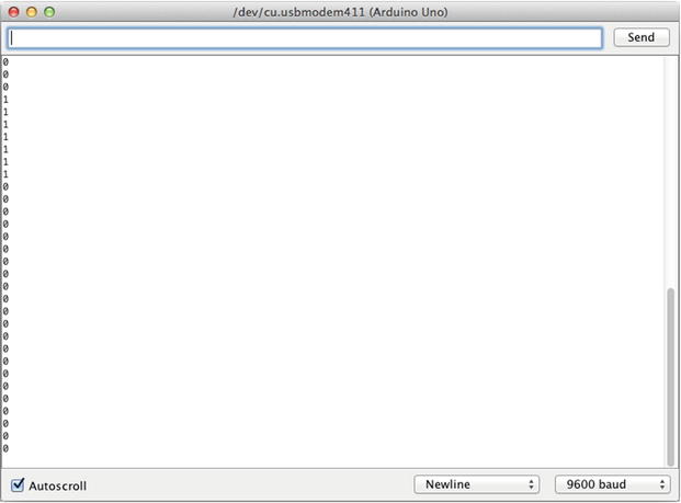
Figure 2-11. Arduino’s serial monitor
Pull-up vs. Pull-down Resistors
There’s one last thing I need to explain before we move on to the next sketch. The resistor used in this circuit is called a pull-down resistor, because it connects the switch to ground. If instead we reverse the connections, so the resistor connects to 5V (any hole along the red line), and the right leg pair of the push button connects to ground (any hole along the blue line), the resistor will be a pull-up resistor. This will create a reversal in the readings of the switch, meaning that the Arduino will print a 1 when you don’t press the switch, and a 0 when you press. This is a bit counter intuitive, but it is said that pull-up resistors are more stable in a circuit, than pull-down. Apart from that, all pins in the Arduino have internal pull-up resistors, which are disabled. To enable a pull-up resistor in a pin, we must call the pinMode function. Open a new sketch window and copy the previous code to it (if you change the code in the previous sketch and upload it, the IDE will automatically save it). In the new sketch change line 6 to this:
pinMode(switch_pin, INPUT_PULLUP);
Also, change your circuit to the one in Figure 2-12. Using Arduino’s internal pull-up resistors reduced the circuit we need to build a bit. This will come in handy when we’ll start building circuits on a perforated board, as it will reduce the amount of soldering to a great extent. These resistors are 20kΩ, but they’re still good for us to use with switches. Don’t confuse them with the internal resistor on pin 13, which we used with the Blink sketch. That resistor connects pin 13 of the processor to the header where we attached the LED, whereas the pull-up resistors connect the pins of the processor to 5V. We first built the circuit with an external resistor, to clarify how the actual circuit works, because if we used the internal one straight away, you probably wouldn’t understand the circuit the same way.

Figure 2-12. Digital input with internal pull-up resistor enabled
A logical next step would be to combine the two sketches we’ve already analyzed. What we’ll do is use the switch both for visualizing it in the Arduino serial monitor, but also to control an LED. Table 2-3 shows the parts needed to realize this project.
Table 2-3. Project 3 Parts List
Part | Quantity |
|---|---|
Push buttons | 1 |
LEDs | 1 |
Resistors | 1 × 220Ω |
This time we’ll use another pin for the LED, that doesn’t have an internal resistor like pin 13 (unlike the pull-up resistors, only pin 13 has an internal resistor that can be used with an LED). Here we’ll also see why it is good practice to store readings in variables, as we’ll use the reading of the digital pin 2, both for projecting in to the serial monitor, but also for controlling the LED. Listing 2-3 shows the code you should write.
This code is very similar to the code in Listing 2-2. What’s new is line 4, where we set a global variable for the pin of the LED, which is 8. In the setup function, we call the pinMode function for both pins, but we set the switch_pin as INPUT_PULLUP, and the led_pin as OUTPUT. Then in line 21, we use the value stored in the switch_state variable, to control the LED, by calling the digitalWrite function like this:
digitalWrite(led_pin, switch_state);
In line 24, we print the value of switch_state to the serial monitor. Instead of creating a variable for the switch readings, we could have called the digitalRead function twice. So line 21 could read:
digitalWrite(led_pin, digitalRead(switch_pin));
And line 24 could read:
Serial.println(digitalRead(switch_pin));
And line 18 could have been avoided altogether. We could have even avoided to create the switch_pin variable, and write the number 2 in its place instead. This whole approach is problematic for the following reasons. The Arduino takes some time to read a pin (especially the analog pins), and calling a function that reads a pin more than once is not very efficient. Calling that function once and storing its reading to a variable, and then calling that variable instead, is much faster, efficient, and easier to read and understand. Also, avoiding a variable for the pin number of the switch can cause some problems, if for some reason we decide to change that pin. If you use a variable, you’ll have to change one line of code only, the variable declaration. If you’re not using a variable, you’ll have to change that pin number in any line of code where you use it. Figure 2-13 shows the circuit for this sketch.

Figure 2-13. Digital input and output circuit
We could have use digital pin 13 for the LED, which has an internal resistor, but we prefer to use an external resistor, so you can see how a circuit using LEDs actually works. Build the circuit and upload your code. Don’t save it yet when the IDE prompts you, just click Cancel and the code will be uploaded without being saved. Open the serial monitor too. Now whenever you press the switch the LED should go off, and whenever you release it, it should go on. But wait a minute, this should be the other way round, right? This inversion happens because of the pull-up resistor we have enabled in the switch pin. The LED should be aligned with the readings you see in the serial monitor. Whenever you press the switch, you should see 0s in the monitor, and the LED going off, and whenever you release it, you should see 1s and the LED going on. We can very easily reverse this whole process by adding a single character to our code. Go back to your code and change line 18 to this:
int switch_state = !digitalRead(switch_pin);
All we did was add an exclamation mark just before digitalRead. The exclamation mark in C/C++ when used before a value (digitalRead returns a value, so we should treat calling it like writing a value) means “the reverse of.” Adding the exclamation mark to this line, should reverse the readings of the digital pin 2, so now whenever you press the switch you should see the LED going on, and 1s in the serial monitor, and the other way round. There should be a tiny bit of lag to the reaction of the LED, which is because of line 27:
delay(250);
This is used to avoid receiving massive amounts of data. We won’t be using that when we build musical interfaces.
Analog Input
The next thing that we’ll look at is getting input from the analog pins of the Arduino. Table 2-4 shows the parts for this sketch.
Table 2-4. Project 4 Parts List
Part | Quantity |
|---|---|
Potentiometers | 1 x 10KΩ |
There are many sensors you can use with the analog pins, like proximity sensors, vibration sensors, accelerometers, and many more. For now, we’ll just use a potentiometer, to see how to use the analog pins of the Arduino. Listing 2-4 shows the code.
This code is also very similar to the code in Listing 2-2. In line 1, we define a variable for the analog pin number. If you look at your board, you’ll see that the analog pins start from A0, up to A5. We can omit the letter A, which stands for analog, but if you like, you can include it and write this line like this:
int analog_pin = A0;
In the setup function, we’re not calling pinMode anymore, because as already stated, the analog pins are input only, so we don’t need to set their mode. We’re just starting the serial communication with a 9600 baud rate. In the loop function, we create a variable to hold the value read by the potentiometer, but this time we call the analogRead function. This function is very similar to its digital counterpart, digitalRead. It takes one argument, which is the analog pin to read from, and returns the value read from that pin. In line 13, we print that value to the serial monitor, the same way we did before. Finally, we use the delay function, in order not to get a massive amount of data. Figure 2-14 shows the circuit for this code.

Figure 2-14. Analog input circuit
The potentiometer is actually a variable resistor. That’s why the ohms are mentioned in the components of this circuit. It has three legs, where one of the side ones connects to ground, the other side leg connects to 5V, and the middle leg (called the wiper) connects to the analog pin of the Arduino. As you spin the potentiometer, the resistance it applies to the circuit varies. It doesn’t really matter which of the side legs will go to ground and which to 5V, only the increasing/decreasing of the resistance will change direction. If you connect the left leg to ground and the right to 5V, then the resistance will drop as you spin the potentiometer clockwise, and the values you’ll receive will increment. If you connect the legs the other way round, this process will be reversed. Most of the time, we want to have incrementing values as we spin the potentiometer clockwise, so you might want to connect its legs as shown in Figure 2-14.
Upload the sketch to your board and when prompted, save it as Analog_input. Open the serial monitor of the IDE and you should see something like the Figure 2-15. As you spin the potentiometer clockwise you should see the values increase (or decrease, depending on the way you built the circuit) and vice versa. The minimum value you get is 0 and the maximum is 1023. This is because the Arduino Uno has 10-bit resolution analog pins. This means that it can express the voltage it receives with 10 bits. In the decimal numeral system, this is expressed as 2 to the 10nth power, which is 1024. Since the number 0 is in that range, what we get is a range from 0 to 1023, which is in total 1024 values. In general, in a number stream that represents a signal, when starting from 0, the maximum value is always (2^bit-depth) – 1 (the ^ symbol raises 2 to the power of the bit-depth).

Figure 2-15. Receiving analog values in the serial monitor
As with the digital pins, we’ll now look at both input and output with the analog pins. Table 2-5 shows the components needed for this sketch.
Table 2-5. Project 5 Parts List
Part | Quantity |
|---|---|
Potentiometers | 1 x 10KΩ |
LEDs | 1 |
Res | 1 × 220Ω |
The name of this section might sound a bit strange, as I’ve already mentioned that the analog pins of the Arduino are input only. By “analog output” I don’t really mean analog, but digital. Six of the digital pins of the Arduino have PWM capabilities. PWM stands for pulse-width modulation. This is similar to the duty cycle of the square wave oscillator we made in Pd. PWM essentially controls the amount of time a digital pin will be HIGH and LOW, during one period of a specified frequency. Quoting from the Arduino web site, “The frequency of the PWM signal on most pins is approximately 490 Hz. On the Uno and similar boards, pins 5 and 6 have a frequency of approximately 980 Hz.” To make this a bit clearer, most PWM pins run at a 490 Hz frequency. When we control the width of the pulse, we control the percentage of the HIGH and LOW states of one period of this frequency, which lasts 1/490 seconds (hertz is a time unit of repetitions per second). During this small amount of time, we control how much of this time the pin will be HIGH, and how much it will be LOW.
PWM can fake a dimming effect when we use LEDs with it. For example, if the PWM pin is 100% HIGH and 0% LOW, then we see the LED being fully lit. If the pin is 50% HIGH and 50% LOW, then we see the LED half lit, and it the pin is 25% HIGH and 75% LOW, we see the LED dimly lit. For this sketch, we’re going to use a potentiometer to control a PWM, where we’ll attach an LED. Listing 2-5 shows the code.
You may have noticed that the more code we write, the less comments we use. Comments are always helpful, but as we start to learn the language, we use self-explanatory code that makes comments in certain cases unnecessary. For example, we don’t use any comments in the first two lines, and by now you should understand what these two lines of code do. Notice that in the setup function, we don’t start the serial communication, as we don’t care to see the values of the potentiometer, since the LED will provide the necessary visual feedback (the brighter the LED, the greater the potentiometer value). We only call the pinMode function to set the mode of the LED pin.
In our loop function, we first store the potentiometer value to a variable, and then we call a new function, map. This function maps a specified range of values to another range. It takes five arguments, which are the variable that holds the range we want to map, the lowest value of the range we want to map, the highest value of the range we want to map, the lowest value of the desired range, and the highest value of the desired range. Notice that we’re mapping the pot_val variable, but we’re saving the value returned by map to the same variable, since we write:
pot_val = map(pot_val, 0, 1023, 0, 255);
This is legal and works as expected. What we see in this line of code is that we want to store to the pot_val variable, the value it holds, mapped from a range from 0 to 1023, to a range from 0 to 255. If the potentiometer has a value of 511, then this line will store the value 127 to the pot_val variable. This mapping is necessary because PWM in Arduino has an 8-bit resolution. Remember that a number stream starting from 0, will go up to (2^bit-depth) -1. 2 to the 8th power, yields 256, minus 1 yields 255.
The last line of the loop function calls the analogWrite function, which is very similar to its digital counterpart, digitalWrite. It takes two arguments, the pin to write a value to, and the value to write to that pin. Here we write to the led_pin the pot_val value. The mapped example of the previous paragraph (511 mapped to 127), will give approximately 50% (127 is almost half of 255), so the LED will look half lit.
Figure 2-16 shows the circuit. As you spin the potentiometer, you should see the LED dimming in and out, looking like a real analog output.

Figure 2-16. Analog input and output circuit
Reading More Than One Pin, Arrays, and the for Loop
We have covered quite a lot of the Arduino language and ways to use it both with analog and digital input and output. Now let’s see how we can read more than one pin, in an efficient way. Table 2-6 shows the necessary components for this sketch.
Table 2-6. Project 6 Parts List
Part | Quantity |
|---|---|
Potentiometers | 3 |
This part may be a little bit tricky, so you might need to go through it more than once. Say that we want to use three potentiometers and print them all to the serial monitor. You could write the following code:
int pot_pin1 = 0;
int pot_pin2 = 1;
int pot_pin3 = 2;

void setup() {
  Serial.begin(9600);
}

void loop() {
  int pot_val1 = analogRead(pot_pin1);
  int pot_val2 = analogRead(pot_pin2);
  int pot_val3 = analogRead(pot_pin3);

  Serial.println(pot_val1);
  Serial.println(pot_val2);
  Serial.println(pot_val3);
}
But this way of writing code is really not efficient, as the more pins we add, the more we have to duplicate code, plus we can’t really group the values we want to read. This is where the for loop comes in handy.
Explaining the for Loop
The for loop has the following syntax:
for(int i = 0; i < some_value; i++)
After this declaration, we insert curly brackets, and inside the brackets we write the code we want to have executed within the loop, much like we do when we define a function (the setup of loop function, only the curly brackets for these functions are there by default). What this loop does is create the variable i and assign it the value 0. Then it goes to the second field, which is a condition. If this condition is met (in this example, if i is less than some_value), the code inside the loop’s curly brackets will be executed, and the loop will go to the last field, i++, which is a shortcut for incrementing i by 1. After that, the condition is tested again, and if it’s true, again the loop’s code will be executed. And this runs over and over, until i is not less than some_value anymore.
Using Arrays in Arduino
Before we apply the for loop to code that we’ll write, I need to explain the array in the Arduino language. This is much like the array in Pd, only there’s no graph of the table. An array can be of any data type (except void) and its declaration has the following syntax:
int pots[3];
This will create an array of three ints, called pots. We can access the elements of the array by means of indexing, much like we did in Pd. So, to write a value to the first element of pots, we must do the following:
pots[0] = some_value;
Applying these two features to our code, we can now write the code in Listing 2-6.
What happens in line 9 is that the for loop will run for as long as i is less than 3, which will happen three times (mind, not less than or equal to three, but only less than 3), as many as the potentiometers we’re using. Note that we use the variable i both for indexing the pots array, but also as the argument to the analogRead function. All this is legal, since i will take the values 0, 1, and 2 sequentially, which are the indexes of the pots array, and the analog pins we want to read. We could have use a for loop for printing the values too, but that would make things a bit more complicated, so we’ll leave it for later. One important thing here is that i is a local variable to the for loop, and as soon as the loop is finished, i won’t exist anymore, until the next the loop will run. The advantage of this is that a local variable is faster to access, and frees the memory it allocates when it is destroyed (when the function defined inside it exits).
Line 13 calls the print function of the Serial class. Its difference to the println function of the same class is that it will print whatever is inside its parenthesis, but anything printed afterward will be printed to the same line. println causes the serial monitor to go one line below after it prints, like hitting the Return key on your keyboard (ln stands for newline). We print white spaces in between the values to get a clearer print on the monitor. Running this sketch and opening the serial monitor, you should get something like what’s shown in Figure 2-17.

Figure 2-17. Reading three potentiometers
Although it is probably rather obvious, Figure 2-18 shows the circuit for this sketch.

Figure 2-18. Three potentiometer circuit
Analog and Digital Input
Now that we’ve seen the for loop in action, let’s write some code that utilizes both potentiometers and push buttons. Table 2-7 shows the necessary components.
Table 2-7. Project 7 Parts List
Part | Quantity |
|---|---|
Potentiometers | 3 |
Push buttons | 3 |
This time we’ll make our code even more efficient, by applying the loop to the printing functions as well. We’ll keep the three potentiometers we used in the previous example, and we’re going to add three push buttons to our circuit and code.
Listing 2-7 shows the code. There are a few new things in this code, so I’ll explain them in detail. Line 2 defines the size of the array that will hold the analog pin values (the array name changed to analog_values to be more generic, and not only potentiometer oriented). Array sizes need to be constant, so when defining its size we must use the const keyword. const makes a variable read-only, which means that we cannot modify it anywhere else in our program. If you omit to use the const keyword when defining the size of an array via a variable, the Arduino IDE will throw an error and won’t compile the code.
Line 4 defines the size of the array that will hold the values of the digital pins, the same way line 2 did for the analog ones. We could have initialized both arrays by writing their size as a number inside their square brackets, but we need these two values in more places in our code, so it’s more efficient to initialize the arrays this way. Lines 7 and 9 initialize the two arrays using the preceding two constant values.
In the setup function we use the for loop to set the mode of the digital pins. This way we only need to write the for loop header (the header of the loop is this (int i = 0; i < num_of_digital_pins; i++)), and one line of code to set the mode of all pins we’re using. In this case, without using the loop, we would write three lines of code, since we use three digital pins, and now we have written two lines, which is not so much less. Imagine if we used all 12 available digital pins. Then we would have saved quite some coding. In general we prefer to use the for loop in many cases of repetition. As stated earlier, we use the num_of_digital_pins constant in the condition test of the for loop. This should make it clear why we prefer to initialize arrays with constants, rather than hard-code their size in their declaration square brackets.
Another thing to mention is that when we define a control structure, like the for loop, if the code of the loop is only one line (like our case, where the code is only pinMode((i + 2), INPUT_PULLUP);), we can omit the curly brackets; we can even write that line on the same line with the control structure’s header. So lines 12 to 14 can also be written like this:
for(int i = 0; i < num_of_digital_pins; i++) pinMode((i + 2), INPUT_PULLUP);
This syntax is perfectly legal. Before we move on to the rest of the code, notice that we add 2 to the i variable inside the pinMode function. This is because i has been initialized to 0 (so we can combine it with the num_of_digital_pins constant, and the for loop can run three times), but we use digital pins from 2 onward. We can see here that a variable of this type is a numeric value and we can apply math operations to it.
In line 19 we run a for loop to read and store the values from the analog pins. Again, we could have omitted the curly brackets. In line 23, we run another for loop to read and store the values from the digital pins we’re using. Again we’re adding 2 to the i variable, as we need to initialize it to 0, so the loop can run properly, combined with the num_of_digital_pins constant.
In line 27, we print an indication that the following values are from the analog pins. The text inside the quotation marks is called a string. A string is essentially an array of characters, used to display text. After we print the string, we use a for loop to print the values of the analog pins. This time we cannot omit the curly brackets, because the code of the loop is two lines. The first line prints the value that is stored in the analog_values array (which we access via the index held in the i variable), and the second line prints a white space, so that the values are separated and easy to read.
Line 33 prints an indication that the following values are from the digital pins, and below that, we run another for loop to print the digital pin values. This time we run the loop for as many times as the number of digital pins we’re using, minus one. This is because we want to print the last value using the println function, so that the values printed in the next loop, will be printed one line below. If we had used only print, then all text and values would be printed in one line, like in Figure 2-19.

Figure 2-19. Printing all data in a single line
Using println for the last value makes things a lot clearer, as one line will contain each value only once. Figure 2-20 shows the serial monitor using println for the last value. Also, the index we use to access the last digital pin is num_of_digital_pins – 1, because num_of_digital_pins is 3, but array indexes start counting from 0, so the last index is 2, and not 3.

Figure 2-20. Using println for the last value
The circuit for this code combines the circuit of the previous code, with the circuit of the push button, in the “Digital Input” section of this book; it is shown in Figure 2-21.

Figure 2-21. Circuit for analog and digital input
Communicating with Pd
Since we’ve covered some basic concepts of Arduino programming, we can now combine it with Pd. As you can imagine, this is possible with the serial communication capabilities of the Arduino. On the Pure Data side, we use [comport], an external object for serial communication. The Serial class of the Arduino language has three functions to send data to the serial line: print, println, and write. We’ve already seen the first two with the Arduino IDE’s serial monitor, but I must explain their differences and how and when to use which of the two when we combine it with Pd.
I’ve already explained the difference between print and println, which is that println adds the newline character at the end, causing the serial monitor to go one line lower. So, for a while we’ll talk about these two functions as if they were one, and we’ll call them simply print. Before I explain this function, let’s talk about write. write writes a single byte, or an array of bytes, to the serial line. This should be straightforward. If we type
Serial.write(100);
we should receive the value 100 in the serial line. This has both advantages and disadvantages. The advantage is that we receive a value as is, but a disadvantage is that we can only receive bytes, and not values longer than that (remember, an int for example is two bytes long, and can’t pass the serial line as is). To send and receive values greater than a byte (an analog pin has a 10-bit resolution and a byte is 8-bit) we must somehow disassemble them before we send them, and reassemble them when we receive them. Another disadvantage of write is that we must make sure we receive the bytes in the correct order, as there’s no default for beginning or ending a stream of data. Another advantage is that we can send whole arrays, which reduces the code we write to a great extent.
print sends anything as ASCII characters. ASCII stands for American Standard Code for Information Interchange, and it’s a 7-bit code (now extended to 8-bit), quoting from http://ascii-code.com/: “Where every single bit represents a unique character.” This means that every character that can be printed on the screen by a computer, takes a unique bit within this 7-bit range, so all characters (except from special Latin characters) get a unique value from 0 to 127. What we most care about is the Latin alphabet, which we use to pass strings over serial, and the 10 numbers of the decimal numeral system. Uppercase Latin letters take the values 65 to 90 (A–Z), lowercase letters take the values from 97 to 122 (a-z), and the numbers from 48 to 57 (0–9) (if you want to check the whole ASCII table, check the ASCII URL earlier, http://ascii-code.com). So, if we use print to pass the string hello, in Pd we’ll receive a list of values, which is 104 101 108 108 111, where 104 is h, 101 is e, and so forth. If we send the number 100, we’ll receive the list 49 48 48, which is 1, 0, and 0 in ASCII. Taken that there is a way to assemble these ASCII values back to the original strings and numbers, using the print function should be easier and more intuitive than using write. Pd doesn’t have an object to do the assembly, still it is possible both with vanilla and extended objects to create an abstraction that does that. I have already made such an abstraction, which you can find in my GitHub page, https://github.com/alexdrymonitis/Arduino_Pd. Download the .zip file, unzip it, and save the abstractions to your “abstractions” folder, so that Pd can find them. We’ll use the [serial_print_extended] abstraction now, but later we’ll use [serial_write] as well (mind, the [serial_print] abstraction is vanilla and won’t work with extended).
Open the serial_print.ino file in the Arduino IDE. Listing 2-8 shows the code without the initial multiline comment.
We have used the code in Listing 2-7 with some minor modifications. In lines 12, 18 and 20 we have three for loops without curly brackets, as we already saw that it is legal and works. This time we print both analog and digital values, all but last with a for loop, and we print the last outside the loop because we have to use println instead of print. This is because of the way the Pd abstraction is made. It receives values in groups, which groups can be recognized by a string, which is used as a tag (here Analog_values: and Digital_values:). Each value group must end with println, because this function adds the newline character at the end (it actually adds the carriage return, and the newline character, which have ASCII 13 and 10 respectively), and this way we can tell that a data stream of a value group has finished. Notice also that we have slightly modified the strings, as we separate their two words with an underscore, instead of a white space. This is because the Pd abstraction uses the white space to separate the string of a group from its values, but also to separate the values of a group between them. Take a close look to each string, they both have a white space at the end. This way we can tell Pd that this is the tag of a value group, and now we’ll start receiving the values. We also print a white space after every value, but the last, which we print with println. Last modification is that we’re not using a delay at the end of our code, since we don’t need it to visualize the values in Pd. Figure 2-22 shows part the help patch of the Pd abstraction.
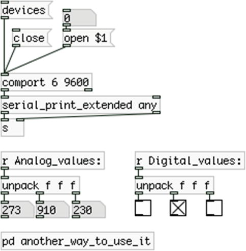
Figure 2-22. The [serial_print_extended] abstraction help patch
In this patch, we use two new objects along with the abstraction. These are [comport] and [unpack f f f]. [comport] is an object for serial communication with devices like the Arduino. It optionally takes two arguments, which are the port number and the baud rate. If no argument is provided, it will try to open port number 0, with a 9600 default baud. When you put this object in a patch, you might get an error message saying that it cannot open the port. This is nothing to worry about. Send the message “devices” to [comport] and you’ll get a list of available serial devices connected to your computer, along with their port numbers, like Figure 2-23.

Figure 2-23. List of available ports in Pd
Figure 2-23 shows a list with four serial ports, where we can see that the Arduino port is number 6 (in this case it’s /dev/tty.usbmodem411, depending on your platform, you should see something equivalent to the port you open in the Arduino IDE). Lock your patch and type the port number in the number atom connected to [open $1(, and [comport] will open that port and print a message declaring that in Pd’s console. Taken that you have already uploaded the code in Listing 2-8 to you Arduino, and that you still have the circuit in Figure 2-21 patched, you should immediately see the potentiometer values in the three number atoms below [r Analog_values:], and the toggles below [r Digital_values:] should go on whenever you press a switch.
I’ll explain how this works. [serial_print_extended] takes in ASCII values from [comport]. The first thing that comes in is a string, which is used as a tag. This string is being assembled to a symbol (in Pd, strings can be displayed via the symbol atom, the fourth element of the Put menu—Ctrl/Cmd+4—or stored in [symbol], an object that stores strings) using the [bytes2any] external object of the moocow library (in vanilla, this is achieved with the new feature of the [list] object, [list tosymbol], which is a bit more efficient). When [serial_print_extended] receives a white space, it knows that the ASCII values of the tag are finished and it sends the assembled tag out its right outlet to the right inlet of [s ]. This way you can dynamically set the destination of [send]. Afterward, the values of the first group arrive one by one, in ASCII. [serial_print_extended] assembles them to their original values and stores them in a list, again using white spaces to separate the values from each other. When the abstraction receives the newline character (ASCII 10) which is sent with the last potentiometer value from the Arduino, it sends the list of values to the left inlet of [s ], which sends that to the corresponding [r ]. In our case, we first print the values of the analog pins, and our tag is Analog_values:. So [r Analog_values:] (we don’t include the white space to the argument of [r ] here, it is used as a delimiter) will receive this list, and will send it to [unpack f f f]. This object takes in a list and unpacks its elements. It will create as many outlets as its arguments (in this case three). “f” stands for float, as you already know, so this specific object unpacks a list of three floats, which we can see in the three number atoms below it.
Once we have received and assembled all analog values, we’ll start receiving the digital values. Receiving the newline character denotes the end of a value group, so [serial_print_extended] knows that we’re done with it and will start assembling the next value group, starting from the string tag. This time the string tag is Digital_values:, so we’ll retrieve these values with [r Digital_values:]. [unpack f f f] below [r Digital_values:] is connected to three toggles, and this is because the digital pins give only 0s and 1s, so a toggle is a nice way to visualize this. The same assembling and listing technique applies here as well, and we can visualize our switches with the three toggles, which correspond to their respective switches in our circuit, from left to right.
The argument of [serial_print_extended] sets the delimiter character, which can be either a white space, a comma, or a tab. Here, “any” means that all three characters will be used as delimiters. So in the Arduino code, we could have used any of the three, in case we didn’t want to use a white space.
You might notice a small lag, especially in the reaction of the toggles compared to when you press or release a switch. This is because we have chosen a rather low baud, 9600. We’ll start using higher baud rates in the code we write, because we want the Arduino to be more responsive. Also, the values in the number atoms should be flickering slightly. This is because there’s a little bit of noise in the circuit, but it’s OK, since the flickering is only a little. So now we’ve seen how to use the print function to receive data from the Arduino to Pd, let’s look at how we can use the write function, and what are the advantages and disadvantages compared to print.
As I’ve already mentioned, write writes a raw byte to the serial line. Open the serial_write.ino Arduino file from the GitHub folder. Listing 2-9 shows the code again without the initial multiline comment.
Lines 6, 7, and 8 are comments explaining how many bytes the array we’ll transfer over serial must have. We’ll now store all values, analog and digital, to one array, and we’ll transfer that array with one function call to Pd. As I’ve already mentioned, the analog pins have 10-bit resolution, but we can only pas bytes through the serial line, and a byte is 8-bit. For this reason, we must split the analog values to two, which we will assemble in Pd. Therefore, we need two bytes for every analog pin. The digital pins will give either a 0 or a 1, and that fits in a byte, so we use one byte only for each pin. Lastly, we need a unique byte at the beginning of the data stream, to denote that we’re starting to receive a new package. Using three potentiometers and three switches, makes 10 bytes in total. Line 9 does the appropriate calculations to get the necessary byte number, using the constants of line 2 and 4. This value is a constant as well, since it will be the size of an array.
In line 12, we define the array that will be transferred to Pd. This array is of the type byte, since we can only transfer bytes over serial. We’re also initializing the array’s first value to 192. This value will denote the beginning of the data stream. This value must be unique, and since we’re sending bytes, we must make sure it will be in a range no other value will ever reach. This range is in the 8th bit.
To understand this, it’s better to visualize it. Think of binary numbers. In an 8-bit binary number, 0 is
00000000
Number 127 is
01111111
This number has the first seven bits on, and the 8th bit off. Number 128 is
10000000
So from 128 onward, we begin to utilize the 8th bit. Any value above that (until 255, which can be represented by 8 bits) will have the 8th bit on, while all values below it (from 0 to 127) will have the 8th bit off. If we make sure that all other values are restricted to a 7-bit range (0 – 127), and assign to the first byte a value between 128 and 255, then this byte will be unique. I got this technique from the rePatcher project by Open Music Labs, where they used 192 as the unique byte, so this is what I use as well. Though, any value between 128 and 255 will do. We’ll also see that in practice along with the Pd patch.
Our setup function is the same as before, only this time we start the serial communication with a much higher baud rate, 57,600. And then we move on to the loop function. Line 21 creates a new variable and assigns the value 1 to it. This variable is called index and it will be used as the index to access elements of the transfer_array. We assign the value 1 to it, because we have already stored the value 0xc0 to the first element of the array, which has index 0.
In line 24, we run the for loop to read and store the values from the potentiometers. We first create a variable of type int, called analog_val, and assign it with the value returned by the analogRead function. In line 27, we read:
transfer_array[index++] = analog_val & 0x007f;
The index++ inside the curly brackets of the transfer_array is called the post-increment technique. This will first use the current value of the index variable, which is 1. So in this line we’re accessing the element with index 1 of the transfer_array. When the whole line has been executed, the index variable will be incremented by 1 (with the double plus sign, ++), so for the next line of code, it will hold 2. The part of this line after the equals sign takes the value stored in the analog_val variable and wraps it around a 7-bit range. This means that when this value is between 0 and 127, it stays as is, but when it goes to 128, it wraps back to 0. As the analog_val value rises up to 255, the result of analog_val & 0x007f will go up to 127, and when analog_val reaches 256, analog_val & 0x007f will again wrap back to zero, and this will happen over and over, for the whole range of analog_val. This happens because of 0x007f, which is the hexadecimal version of the number 127. Hexadecimal values are useful here because we can express the size of a value without needing to define it as a specific data type (an for example). Since analog_val is an , when we apply operations to it, we need to use the same data type, or a value with the same length (two bytes in this case). A hexadecimal number can express 256 values with two digits, from 00, which is 0, to ff, which is 255. This is the range of one byte. Using four digits, we can express a value in the range of two bytes, which is the same as an int. The 0x prefix is the C++ prefix to indicate a hexadecimal value. So, without having declared a variable of the type int, we can use the hexadecimal value here to indicate the same length of the int data type, and be sure that our operations will have correct results.
Line 28 again uses the post-increment technique, where index now holds 2, so we’re accessing the third element of the transfer_array. The second half of the line reads:
analog_val >> 7;
What this does is shift the bits of analog_val by 7 positions to the right. The result of this is a number that increments by one, whenever the line wraps back to 0. By restricting both values to a 7-bit, we can be sure that no analog value will ever reach the first byte of the array, which is 192, in the 8-bit range. All this might sound very strange, but when we look at the Pd patch, where we reassemble these values, it will start making sense.
In line 32, we read and store the value of the digital pins to transfer_array, again using the post-increment technique we used in the loop. This time the code of the for loop is one line below, without curly brackets. This syntax is also legal, since the executable code is only one line. We indent it manually (the IDE won’t do it automatically if there are no curly brackets) to make the code more readable.
Lastly, in line 36 we call the write function, of the Serial class, to write our array to the serial line. When we write an array using this function, we must provide two arguments, the name of the array, and the number of bytes we want to transfer. Usually we want to transfer the whole array, so we’re using the constant that sets the size of it, num_of_bytes. Notice that we’re using names that explain what each variable or array does, so we can restrict our comments to a minimum, making our code self-explanatory.
Now let’s check the help patch of the [serial_write] Pd abstraction, part of which is shown in Figure 2-24.
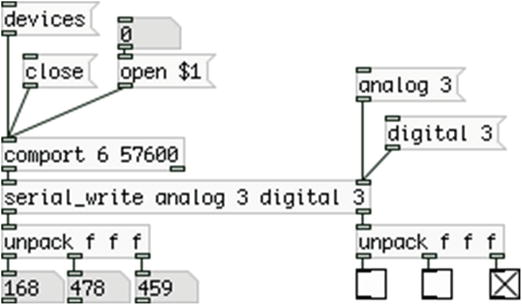
Figure 2-24. Pd [serial_write] abstraction to read bytes sent from Arduino with Serial.write()
The first thing to notice is that we are using arguments with [comport], which are the port number and the baud rate. From Figure 2-23, we’ve seen that the Arduino port on my computer is number 6, so I’m using this number for the first argument. You should use the number of your serial port, which is very likely to be different. If you don’t remember which one it is, send the “devices” message to [comport] and it will print all available serial ports to Pd’s console. This time we’re also using a higher baud rate, which is 57,600, so we use that as the second argument (the comma is used only in the text of this book. When programming, use the number 57600 (as in Figure 2-24).
Again, it can be quite cumbersome to receive and assemble all the data we receive from the Arduino, so I have created another abstraction for this purpose, [serial_write], which is included in the GitHub link I posted earlier. This abstraction takes two to four arguments. The first argument is the type of pins we’re reading (analog or digital), and the second is the number of these pins that we’ll be reading (in this case 3). We use the third argument is in case we’re reading both types of pins, analog and digital, so depending on the first argument, this will set the other type of pins (in this case we first read the analog pins, so the third argument is “digital”). The last argument is the number of pins of the second type that we’re reading (again 3, as we have three potentiometers and three switches). The first and third arguments cannot be set any way we want, but must be aligned with the Arduino code. In our code, we first store the analog values, and then the digital, so we must type our arguments in this order.
[serial_write] will output the values of the first argument (the analog values) out its left outlet, and the values of the third argument (the digital ones) out its right outlet. We’re again using [unpack f f f] to unpack the lists we’re receiving so we can see these values in the number atoms and the toggles.
It’s not necessary to know the workings of [serial_write], but to make the Arduino code a bit clearer, I must explain a couple of things. As already mentioned, an abstraction is clickable. So in a locked patch, if you click it, the abstraction window will open. In there, click [pd $0-route_list], then click [pd specify_analog], and then click one of the two [pd assemble_analog] subpatches. The patch in Figure 2-25 will open.

Figure 2-25. The assemble_analog subpatch of [serial_write]
This subpatch receives the list of the analog values. Since we’re splitting the analog values to two, this subpatch will receive a list with elements two times the number of analog pins we’re using. It then goes on to split this list and separate the first two elements, using [list split 2], which comprise the first analog value. These two values are sent to [unpack] (no arguments to this object is equivalent to [unpack f f]), which unpacks the two element list and makes the operations below it. Bearing in mind the right-to-left execution order in Pd, the second element will come out first, and the first element will come out second. In Pd, apart from right-to-left, the depth-first execution order applies as well. This means that the right outlet of [unpack] will go to [* 128] and then to the right inlet of [+ ]. Since the right inlet is cold, all execution will stop there, and only then will the left outlet of [unpack] spit its value.
Now remember the operations we did in the Arduino code. We split each analog value to two, and wrapped the first one to a range between 0 and 127, so whenever the analog pin would read 128, we’d get 0 and start incrementing anew, up to 127, and then wrap back to 0 again. The second element of this list is a number that increments by 1 (starting from 0) whenever the first element wraps back to 0. So, for the first 127 values, the second element will be 0, which will be multiplied by 128, which will again be 0, and will be stored to the right inlet of [+ ]. So as the first element goes from 0 to 127, it will be added to 0, so it will stay intact.
When the first element wraps back to 0 for the first time, the second element will be 1 × 128 = 128, which will be added to the first element, so we’ll get 0 + 128 =128, the next number after 127. As the first element again increments to 127, we’ll get 127 + 128 = 255, and then it will wrap back to 0, and the second element will be 2 × 128 = 256, the next value after 255. And this goes on until we get 1023, which is the maximum value of the 10-bit resolution (2 to the 10th power, minus 1). After the first two elements of the analog values list is assembled, the next two elements will go through this process, and the next two, until we reach the end of the list. Don’t worry so much about how exactly this subpatch works, what you need to know is how we combine the Arduino code with the Pd patch.
Figure 2-26 shows a simple Pd patch that helps visualize this technique. Go ahead and build it and drag the values of the top number atom, from 0 to 1023 and check the other four number atoms to see how it really works.
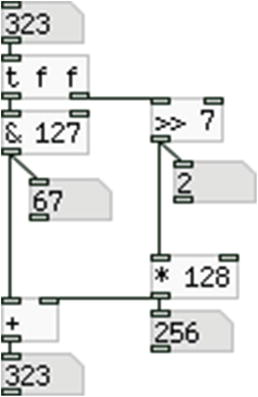
Figure 2-26. Visualization of the Arduino-Pd technique for the Serial.write() function
We’ve covered both ways of communicating the Arduino to Pd. Each has its own advantages and disadvantages, plus they might seem a bit difficult to use. The advantage of both is that we can more or less use them the way we’ve showed them here, for any number of pins we’re using, doing only minor changes to both Arduino and Pd. So we have a tool to help us combine the two platforms, without needing to write all the code from scratch every time. This shows the great advantage of using abstractions, where one patch can be used many times, without needing to create it anew. When to use which of the two techniques depends on the project. We’ll use both in the projects of this book, but not at the same time, as in one project it might be better to use one technique, and in another it might be better to use the other technique.
Sending Data from Pd to Arduino
Let’s build the final project of this chapter where we’ll send data from Pd to the Arduino. Table 2-8 shows the components needed for this sketch.
Table 2-8. Final Project Parts List
Part | Quantity |
|---|---|
LEDs | 3 |
Resistors | 3 × 220Ω |
Until now, we’ve covered the communication between Arduino and Pd, where the Arduino was sending data to Pd. Now let’s look at this communication the other way round, we’ll send data from Pd to the Arduino. The simplest form the Arduino code can take is shown in Listing 2-10.
Up until the loop function, there should be nothing new. In line 10, there is something we haven’t encountered yet. This is the if control structure. Like the for loop, if has code of its own, written inside its curly brackets. What if does is test the statement inside its parenthesis. The following line of code demonstrates how this test works:
if(some_variable){
  // code to be executed if the test above is true
}
The code inside the curly brackets (here it’s only a comment) will be executed only if some_variable is true. True in the Arduino language is any non-zero value, and this concept is often used in control structures like if. If some_variable is not true (if it’s zero), then the whole code inside the curly brackets will be skipped and we’ll move further down to our program.
Inside the parenthesis of the if control structure in Listing 2-10, we call the available function of the Serial class. Quoting from the Arduino web site, this function will “get the number of bytes (characters) available for reading from the serial port”. This means that if there are any bytes available in the serial port, then available will return a non-zero value, so the statement inside the parenthesis will be true, and the code inside if’s curly brackets will be executed. This means that whenever we send something from Pd to the Arduino, Serial.available() will be true.
Inside the curly brackets of the if control structure, we define a variable of type byte, and assign it the value returned by the read function, of the Serial class. This function will return the first byte of the incoming serial data, so it will assign to in_byte whatever value we send from Pd. Then we use this variable to set the state of the led_pin, in line 12. The Pd patch that works with this code is extremely simple, and it’s shown in Figure 2-27.

Figure 2-27. Simple patch to control an LED of the Arduino
All we need to do is send either a 1 or a 0 to [comport], and the integrated LED of the Arduino board will turn on and off accordingly. What if we want to control more than one pin on the Arduino? This technique is not efficient because we cannot really separate bytes we send to the Arduino, so we’ll have to use another technique. Listing 2-11 shows a way to control various pins of the Arduino from Pd.
Now we’ll use an array to store the pins we want to control. In line 1, we set the size of the array, and in line 3, we define the array and initialize it. Initializing an array, means to provide values for it, and the syntax is the one used in line 3, we use curly brackets to include the values of the array, which are separated by commas. Here we use the pins 3, 5, and 6, because they are PWM pins, and we want to control LEDs with PWM. In the setup function we set the mode of the pins as OUTPUT with a for loop, where the variable i is used as the index to access the elements of the led_pins array. Then we start the serial communication.
In the loop function, we use the same if statement as before, but its code is very different. Line 13 defines a variable of type int, which is static. A static variable means that it is a local variable, but it retains its value even when the function, which it belongs to has ended. We must define the variable as static, otherwise the code won’t work. Line 14 stores the incoming bytes, one by one. In line 15 we use another if statement, this time using a Boolean AND (the double ampersand, &&). All Boolean operations utilize the concept of truth and falsity. The Boolean AND tests both sides, and only if both sides are true, it will be true, otherwise it will be false. So the if statement in line 15 will be true only if both (in_byte >=’0’) and (in_byte <= ’9’) are true. The numbers inside single quotes represent the ASCII values of these characters, which are 48 and 57, respectively. This tells us that the data we’ll be sending from Pd to the Arduino will be in ASCII form. If this statement is true, the code of line 16 will be executed.
Notice that the code of this if statement is one line only, so we don’t need to use curly brackets, still we’re writing it one line below, and not in the same line with the declaration of the control structure. This is legal as well, and we indent this line to make the code more readable (this time, the IDE won’t indent the cursor automatically, you need to do it manually).
The executable code of the if control structure reads:
temp_val = temp_val * 10 + in_byte – ’0’;
These simple operations will assemble a value passed as ASCII. Let’s say that we send the value 152 from Pd, in ASCII. A list with the values 49, 53, and 50 will arrive to the serial line of the Arduino. The preceding line of code will run three times, because the if statement in which it is included, will be true for all the three values. The first time temp_val hold nothing, which is equivalent to zero. Multiplying this by 10 will give zero, adding in_byte , which will hold the first value of the three, will give 49, and subtracting ASCII 0 (0 in single quotes), which is 48, will give 1. The second time temp_val will hold 1 × 10 = 10 + 53 (the value in_byte will now hold) = 63 – 48 (’0’) = 15. The third time temp_val will hold 15 × 10 = 150 + 50 = 200 – 48 = 152. This way we can assemble values arriving in ASCII. This is the same technique used in the [serial_print] abstraction.
Line 17 calls the else if statement. This is an optional statement when we use the if control structure. The else if statement will be tested only if the if statement it is false. In Pd, we send messages of the type “200a”, where 200 is the value for the PWM, and “a” the PWM pin to use. After the numeric value has been assembled, the if statement of line 15 won’t be true and the program will move on to the else if. The serial line will now have the ASCII a, which is 97. Indeed, line 17 tests if the current byte from the serial line is between ASCII a and ASCII z, which are 97 and 122, respectively. So this line will be true and its code (now inside curly brackets, as it’s more than one line) will be executed. This statement’s code creates a variable called which_pin, and assign to it the value in the serial line, minus ASCII a, which is 97. If the byte in the serial line is indeed ASCII a, line 18 will assign the value 0 to which_pin. Line 19 calls the analogWrite function, and passes as arguments the led_pins array using which_pin as the index, and temp_val as the value. Since which_pin is 0, led_pins[which_pin] accesses the first element of the led_pins[which_pin] array, which is the value 3 (check line 3). So line 19 will write the value 200 to digital pin 3.
When we’re done writing to the digital pin, using the analogWrite function, we assign 0 to temp_val, so that we can start assembling value from scratch (temp_val is static, so it will retain its value, therefore we must zero it). Figure 2-28 shows the circuit for this code, and Figure 2-29 shows the Pd patch.

Figure 2-28. PWM from Pd

Figure 2-29. Pd patch for controlling PWM pins in Arduino
Again, this is a very simple patch, where we send messages to [comport] of the type “print $1a”. The word print in the message converts the elements of the message to their ASCII values, which is necessary to manipulate the data in the Arduino code. $1 will take the first value of a list that arrives to the inlet of the message, and since we send one value only, $1 will take that value. So in the patch in Figure 2-29, the three messages are actually “print 124a”, “print 52b”, and “print 255c”. Going back to the Arduino code, we see that the letters are converted to indexes in order to access the led_pins array. So the message “print $1a” will control the LED on pin 3, the message “print $1b” will control the LED on pin 5, and the message “print $1c” will control the LED on pin 6 (these are the three elements of the led_pins array, check line 3 of the Arduino sketch). Upload the code to the Arduino. ([comport] must have its port closed to upload code to the Arduino using its IDE, so send the message “close” to [comport] and when you’ve uploaded the code, send the message “open port number”, where port number is the number of the Arduino port—in Figure 2-29 it is 6.) Open the Arduino port in the Pd patch and start playing with the number atoms. You’ll see the LEDs dimming in and out, as you send various values between 0 and 255. This concludes the communication between Arduino and Pd, and the whole chapter.
Conclusion
We have gone through the basics of the Arduino language, and some very simple circuits. What has been covered in this chapter will be sufficient for most of the projects we’ll be building in this book. Even if we encounter something new in one of the projects, we’ll be able to easily understand it, since we have been introduced to the philosophy of the Arduino language and electronics. For all code in this chapter, we used push buttons for the digital pins, and potentiometers for the analog ones, but further on we’ll use different kinds of sensors, depending on the project. So even though we used the same elements to build all the circuits, we have gained the foundation to comprehend and build other kinds of circuits, using the Arduino.
All circuits in this chapter were built using a breadboard, since they were testing circuits, and not a final version. In the building projects of this book, we’ll use perforated boards, which make it possible to build more steady circuits, compared to the breadboard. To build circuits using a perforated board, you must be able to solder. Explaining how to solder is beyond the scope of this book, but there are many tutorials on the web, so it shouldn’t be too difficult to learn how to solder yourself.
The last part of this chapter covered the communication between the Arduino and Pd, both directions. You should be able to see the potential of this, since being able to use various kinds of sensors and receive their input in Pd, gives infinite possibilities as to what you can build. There are many kinds of different sensors, proximity sensors, accelerometers, tilt sensors, gyroscopes, even humidity sensors, and so forth. The only limitation as to what you can realize is your own imagination. Being able to also give input from Pd to Arduino, expands the possibilities one has using these platforms. The Arduino can give input to the physical world, not only with LEDs, but also with motors, solenoids, and so forth. Bearing in mind the simplicity of the Arduino language, along with the provided tools for the communication between it and Pd, you should just let your imagination take over, and realize things you might have thought impossible, or even come up with things that never crossed you mind.
Lastly, you might want to sign up to Arduino’s forum, in case you have questions regarding it. You can find that on Arduino’s web site. Take care when signing up to mailing lists and forums, to read the “rules” before posting. Search the web before you post a question, as it is very possible to find the answer, since someone else before you might have had the same question, and since forums and mailing lists keep an archive, it’s rather easy to search for solutions. Nevertheless, if you play nice, you will be warmly welcomed to these communities, and you’ll find people willing to answer your questions.
Now on to embedded computers and wireless use of the Arduino.
______________________
1On OS X there’s a /dev/tty.usbmodemx and a /dev/cu.usbmodemx. It used to be the tty. but the latest IDE hides it. Selecting the cu. one is exactly the same.