
![]()
A Simple Synthesizer Using a MIDI Keyboard and Arduino
In this chapter, we’ll start building interfaces that can really be used for expressing musical ideas. Our first project will be a clavier synthesizer. For this interface, we’ll use a MIDI keyboard to control the pitch of the synthesizer, and the Arduino for various other types of control parameters. If you have a MIDI keyboard that provides potentiometers, pitch-bend wheels, and push buttons, you might want to avoid using the Arduino altogether. Still, the Arduino has a better resolution in its analog pins, so you might find that it provides more room for expression when it comes to sound quality control parameters. In this chapter, we’re going to cover different types of MIDI keyboards, from the new USB MIDI to the old-style 5-pin DIN cable MIDI. In the case of the latter, using an Arduino will be necessary if you want to avoid buying a MIDI-to-USB converter, which might be rather expensive.
The idea behind this project is to revive any old equipment that you might have lying around. I found a 30-year-old keyboard synthesizer in my house, which hasn’t been used for decades. Even though it’s a very old instrument, it does have MIDI, although with the old 5-pin DIN cable. This is where the Arduino came in handy—with a simple circuit and very cheap components, I managed to receive input from the synthesizer and send it over to my computer. This is not a real MIDI-to-USB converter, as my computer doesn’t see the Arduino as a MIDI device. Still, it’s possible to send the messages received from the keyboard over to the computer “MIDI style,” so you can use the keyboard to control you oscillators in your Pd patch. If you have a USB MIDI keyboard that you’d like to use to hack and create a brand-new synthesizer, use that instead, as it will save you from some circuit building and some coding too.
In this project, we’ll end up with an interface with an embedded computer (a Raspberry Pi) that will be enclosed in the synthesizer. For this reason, I chose to use an Arduino Nano instead of the Uno, as it is much smaller and destined to be enclosed in projects. It is a bit more expensive than the Uno, but it has the same capabilities and fits in very small enclosures. Also, it provides eight analog inputs, which seems quite necessary for this project. You are welcome to use whichever Arduino you like best. If you use an Uno, which has fewer analog pins, you’ll have to compensate by reducing your control parameters.
I’ll provide some suggestions as to how this project can be implemented with fewer control pins as we build the Pd patch. You are not obliged to embed a computer to your own implementation of this project. If you want, you can do all the coding and patching, but keep your devices outside enclosures. This may be because you have a MIDI keyboard that you use for other reasons too, and you don’t want to hack it and transform it to something else. You might also want to use your laptop instead of a Raspberry Pi, because you already have an external sound card. The way this project is built is only a suggestion. You are welcome to make your own version of this or any other project in this book.
Another thing that we’ll cover to some extent is external sound cards. We’ll go through a few different options for the Raspberry Pi, and how to use them with Pd. Not using one won’t affect the project very much, as we’re not going to receive audio input. The difference will be that the audio without an external sound card will be a bit lower in volume, and it will have some noise. If you don’t have one, you can always build this interface without it, and if you want, you can get one in the future and come back to this chapter to get information as to how to use it with Pd. Now let’s get started.
You may find some of the patching or coding in this project a bit complex, so you might want to go through the chapter more than once. In any case, stay focused during the whole process, and if there is something you don’t grasp during your first read, go ahead and read it again. It’s all a matter of programming with the two languages—Pd and Arduino, so eventually it should all come together and make sense.
Parts List
Table 5-1 lists the parts we’ll need to build this project.
Table 5-1. Parts for this Project
Part | Quantity |
|---|---|
Arduino | 1 (preferably Nano) |
MIDI keyboard | 1 (USB or 5-pin DIN) |
Optocoupler | 1 × 4N35 or 4N28 |
Potentiometers | 8 × 10 kiloohm |
Push buttons | 4 (to mount on panel) |
Switches | 5 (to mount on panel) |
LED | 1 |
Resistors | 1 × 220Ω 1 × 3K3Ω 1 × 100KΩ |
Diodes | 1 × 1N4248 (diode type) |
What Is MIDI?
Before we start using MIDI with Pd, I should talk a bit about MIDI itself. MIDI stands for Musical Instrument Digital Interface, which is a communication protocol, digital interface, and connector type (although the standard MIDI cable has mostly been replaced by the USB type one), that allows for communication between different devices, for control of musical applications. There are quite some different kinds of MIDI messages a MIDI device and deliver or accept, and we’re going to use some of the here. MIDI was initiated in 1983 and it’s still a prevailing interface in digital (sometimes interfering with analog too) electronic music. Even though it’s so old, it still hasn’t been replaced by another protocol. The OSC (Open Sound Control) protocol started off as a replacement for MIDI, but as it developed, it took another route, and ended up in a more network oriented communication protocol.
MIDI devices enable us to physically control various aspects of our musical applications. Different types of control interfaces, like keyboards, potentiometers, pads, foot pedals, push buttons, and so forth provide a wide variety of controllers, which we can use to create various musical interfaces. All this might sound a bit similar to the use of the Arduino we make in this book. Although MIDI and Arduino are two different things, they both aim at control and communication (the Arduino has a wider range of capabilities, like motors and solenoids, for example). At least the way we use the Arduino here is very similar to the way MIDI controllers are used. Why not use MIDI devices and avoid Arduino programming in the first place? One drawback of MIDI (at least in my point of view) is that first of all, MIDI controllers are rather expensive compared to their quality, and secondly, one depends on the products of the market. With Arduino you can build really unique control interfaces that cannot be found on the market (you can only find the components of such an interface on the market, but not the interface assembled and programmed), and the overall cost will be much smaller. In addition to that, the high resolution of the Arduino’s analog pins provide much more flexibility in controlling the sound aspects.
In this chapter, we’re using MIDI mostly because of the keyboard interface you can easily find in the market. Building a keyboard is a difficult task that can cause a lot of frustration to someone who is not experienced in electronics. Since a MIDI keyboard is something very common, and many people using a computer for music (in any way) do have one lying around, it’s a good idea to start with something like this, as the first finished project of this book. I’ll assume you have a MIDI keyboard. If it has a MIDI cable, I’ll assume you have a MIDI-to-USB converter or a sound card that has a MIDI connector, so that you can connect the keyboard to your computer. If you have a MIDI cable controller, later in this chapter, you’ll see how to get its input using the Arduino.
Pd and MIDI
Using MIDI in Pd is quite simple. This project is based on a keyboard, so we’ll first cover the use of MIDI keyboards in Pd. To be able to use a MIDI device with Pd, you need to plug the device in your computer before launching Pd. Once you launch Pd, set your keyboard as a MIDI input device, as shown in Chapter 1. The object that receives data from MIDI keyboards is [notein]. Figure 5-1 shows [notein] receiving input from a MIDI keyboard.

Figure 5-1. The [notein] object
How [notein] Works
[notein] has three outlets. The leftmost outlet outputs the MIDI note number. In Figure 5-1 we see MIDI note 60, which is the middle C. The middle outlet outputs the velocity, which means how hard the key is pressed (hence, the dynamic of the note, in more musical terms). The rightmost outlet outputs the MIDI channel the device is talking to. The channel can be set via an argument, in which case [notein] will have only two outlets, one for the MIDI note number, and one for the velocity. MIDI notes, as well as velocity, counts from 0 to 127, with 127 velocity being full amplitude. The channel is used to avoid clashes with other MIDI controllers used simultaneously. Check its help patch for more information.
To use [notein] in a meaningful way, we also an object to convert the MIDI note numbers to frequencies, so we can control oscillators this way. Pd has a built-in object for that, [mtof], which stands for MIDI to frequency. Figure 5-2 shows how to use these two objects to control the pitch and amplitude of an oscillator. In this figure, we see that the incoming note is MIDI note number 69 (which by the way is the tuning A) and the velocity is 116. The MIDI note goes through [mtof] which converts it to the corresponding frequency (440 in this case), and then sent to [osc~]. The velocity is first divided by 127, because 127 is the maximum velocity we get from MIDI keyboards, and the maximum amplitude value we should use is 1. The result of the division is sent to [line~] to smooth the possible clicks of the control and signal domain combination, and is then multiplied with the oscillator’s output to control its amplitude. The number atoms used in the figure are not necessary, and it’s better to avoid them when not needed, as they require a CPU, but there’re there to demonstrate the conversions from one type to the other. Go ahead and build it to see how MIDI keyboards are used in Pd.
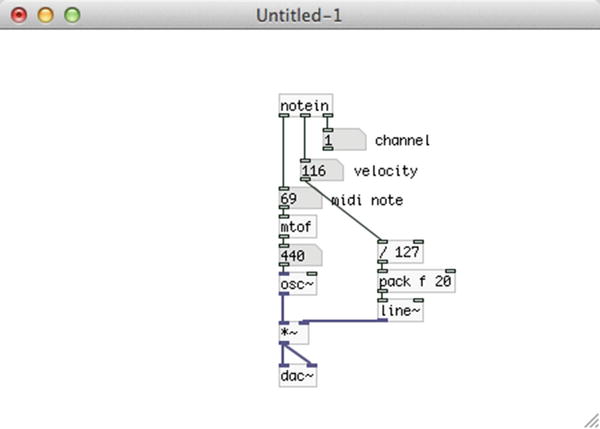
Figure 5-2. Using [notein] and [mtof] to control an oscillator
Using a Different Tuning and an Amplitude Envelope with [notein]
The patch in Figure 5-2 demonstrates the simplest use of [notein], and we can see that two issues arise from this kind of use. First, we have a fixed tuning at 440 Hz, which is not the case with most acoustic instruments, as modern tuning is usually at 442 Hz or higher, and other kinds of music might use different tunings, like early music for example. The other issue is that this patch doesn’t make use of an amplitude envelope, making the audio output sound rather mechanic. A solution to the first issue is provided by the [mtof_tune] abstraction, which is included in the miscellaneous abstractions GitHub page already provided. This abstraction lets you set the tuning A pitch to any frequency you want, and will then convert MIDI notes according to that pitch. The second issue can be solved by using [ggee/envgen], which helps us create amplitude envelopes in a user-friendly way. Figure 5-3 illustrates the use of the [mtof_tune] abstraction and the [ggee/envgen] external.

Figure 5-3. Using [mtof_tune] and [ggee/envgen] to set tuning and amplitude envelope
Our patch has now become a bit more complex. The easy part is the left side of the patch, where we use [mtof_tune] instead of [mtof], with a 442 argument, and we can see that the tuning A produces a 442 Hz frequency, which is very likely to be desired if a synthesizer is combined with acoustic instruments. The right side of the patch applies an amplitude envelope with [ggee/envgen]. We first connect the velocity value to [sel 0], and connect the right outlet of [sel 0] to [t b f]. [sel 0] will output a bang out its left outlet when it receives a 0, and anything else will be output out its right outlet intact. We do this to strip the 0 velocity from the message, as we only care for the maximum velocity of each key press since the amplitude envelope we use has a fixed length and it doesn’t need a 0 velocity to end. [t b f] will output the maximum velocity of the key press out its right outlet which goes to [/ 127] below [ggee/envgen], and a bang out its left outlet which goes into [ggee/envgen], triggering the envelope. We multiply the output of [line~], which is triggered by the envelope, with the normalized velocity of the key press, because if we used the envelope as is, no matter how hard or soft we hit the keys, we would always get the same amplitude envelope. This way we map the envelope to the velocity of the key press, making it responsive to our playing. [ggee/envgen] has a very short duration by default, but we can set the duration we desire with the “duration” message, as shown in Figure 5-3. Mind that if you hit a key before an envelope has finished, you’ll get a click. This is solved later on with the use of an abstraction.
Holding the Sustain Part of the Envelope
We have solved the frequency and envelope issue, but the [ggee/envgen] external has introduced another issue. It’s very common among synthesizers to hold a note as long as the corresponding key is pressed. This is usually done by maintaining the sustain part of an ADSR envelope while a key is pressed. [ggee/envgen] has a fixed duration, and doesn’t provide this feature. What this object does is output lists for [line~], where each list is delay by the amount of the ramp time of the previous list. To be able to hold a note while a key is pressed, we must hold the last list output by [ggee/envgen] until we receive a 0 velocity from the MIDI keyboard. I have made an abstraction that does this called (not surprisingly) [hold_sustain], which you can find on GitHub https://github.com/alexdrymonitis/envelopes. This abstraction takes in lists from [ggee/env] and holds the very last list, until it receives a 0 in its left inlet, which is when it will output the last list. It takes one argument, which is the amount of breakpoints our envelope has (disregarding the start and end breakpoints), and according to that argument, it will hold the last list. Even if the release ramp takes a lot of time, and we send a new note before the release has ended, [hold_sustain] will hold the new lists, until the release ramp has ended. Figure 5-4 illustrates the use of this abstraction.

Figure 5-4. Using the [hold_sustain] abstraction to hold the sustain part of an ADSR envelope while a key is pressed
The patch in Figure 5-4 is almost identical to the one in Figure 5-3, only this time when we receive a 0 velocity we bang a 0 message and send it to [hold_sustain] (remember, [sel 0] outputs a bang from its left outlet when it receives a 0, it doesn’t output 0). The envelope now has a longer release ramp, so you can test the delay applied to a new note when the envelope is retriggered before the release ramp has ended.
Polyphony with MIDI in Pd
The preceding examples utilized MIDI to control one oscillator. This setup is monophonic, as there’s no way to have two distinct notes at the same time with only one oscillator. To have polyphony, we’ll need to use more oscillators, and a way to allocate the MIDI notes to each voice. Luckily, Pd has a built-in object for voice allocation, [poly]. [poly] takes in MIDI notes and velocities and outputs a list consisting of a voice number along with the MIDI note and the velocity for that voice. When a new note comes in, while the previous is still playing, [poly] will send the new note to another voice, keeping the previous voice reserved until it is freed, which will happen when [poly] receives the MIDI note number of that voice with a 0 velocity. The number of voices is set via an argument to [poly]. Sending the MIDI note and velocity to the voice specified by [poly] is achieved using [route]. Figure 5-5 illustrates the use of [poly].

Figure 5-5. Using [poly] for MIDI polyphony in Pd
We have placed the voices in subpatches for cleanliness. Also [s~ out] and [r~ out] is there for patch cleanliness, as it saves us from patching some cords. The left and middle outlets of [notein] go to the two inlets of [poly], which outputs the lists of voice number along with MIDI note and velocity. These values are packed and sent to [route], which will route the MIDI note number and the velocity, according to the voice number. Figure 5-6 illustrates the contents of the [pd voice~] subpatch.

Figure 5-6. Contents of the voice~ subpatch
At the top of the patch, we’re receiving the list with the MIDI note and the velocity, which is unpacked and sent to its destinations. There’s a [r envelope_data] connecting to the inlet of [ggee/envgen], which will receive various data concerning the envelope. This is because it is cumbersome to make the envelope for each voice by hand, plus there’s no way that the envelopes will all be the same, if done manually. Also, if we want to set the duration for the envelopes, it’s easier if there is a global “duration” message that will affect all envelopes. Even for this patch that has only four voices, doing all this by hand can be tiring, let alone if we want to create more voices, like 10 or 20!
To create the envelopes for all subpatches, create the envelope you want in the parent patch, and click the “dump” message. When [ggee/envgen] receives these messages, it outputs its points’ values out its right outlet. This list is sent to [s envelope_data] going to the inlet of each [ggee/envgen] in all subpatches, which will create exactly the same envelope. The same applies to the “duration” message, which is sent to all subpatches too. Now if you play with your keyboard, you’ll see that you can have four voices simultaneously.
In Figure 5-5, we see that [poly] has two arguments. The first one is the number of voices it will create. The second one enables or disables voice stealing (which is disabled by default). Voice stealing is the technique where if one note too many arrives, [poly] will zero the oldest note in its list and will allocate the new note to that voice. The same goes for even more notes that arrive. For example, if you play an arpeggio of a 9th chord, you’ll first send C, then E, then G, then B, and lastly D. When D arrives, [poly] will zero C and will send D with its velocity to the voice that was playing C. Try it to get a better understanding of how voice stealing works.
MIDI Control Messages in Pd
Let’s now look at another type of MIDI message, the control message. This type of message is sent from MIDI devices with potentiometers and foot pedals. You MIDI keyboard is very likely to have potentiometers as well. In Pd, you can retrieve these messages with [ctlin], which stands for control in. If your MIDI keyboard has potentiometers on it, use that, otherwise plug in a MIDI controller with potentiometers or pedals (keep your keyboard plugged in too). If you plug in a new controller, you’ll have to restart Pd, so it can see it. Go to Media ä MIDI Settings... and click Use multiple devices to use both MIDI controllers. On Linux, you’ll need to set the In Ports: to 2 and then use aconnect -lio on your terminal to see all MIDI devices and applications and make the appropriate connections in the same line as we did in Chapter 1 (using ALSA-MIDI). Choose your keyboard as Input device 1:, and your potentiometer controller as Input device 2:, click Apply and then OK. Now open the polyphony patch we created earlier so that we can work on it a bit more. Place a [ctlin] object and check its help patch. This object has three outlets as well: [notein], which output the controller value, the controller number (there’s one number for each potentiometer), and the channel the controller is talking at. Open one of the subpatches and apply the changes shown in Figure 5-7.

Figure 5-7. Contents of the voice~ subpatch, receiving data from [ctlin]
In this subpatch we’re applying phase modulation, like we did in the first project in Chapter 4. [r oscillator_data] on the top part of the subpatch receives input from the parent patch, and we’re using [route] to diffuse that input to where we want. We’re using two potentiometers (or sliders) to control the detune of the modulator oscillator and the index of the modulation. The detune value goes to [t b f], because we’re sending it to the cold inlet of [* ]. Using [t b f] we’re banging the hot inlet of [* ] whenever we send a new value to the cold inlet, thus producing output. If we press and hold a key, we can use this value to instantly change the modulator frequency while the voice is still sounding. If we didn’t use [t b f], we would have to wait until we hit a new key to hear the new frequency, and that is not very nice. Try the subpatch with and without [t b f] to hear the difference (without [t b f], the left outlet of [route] goes to the right inlet of [* ]).
Figure 5-8 shows the parent patch. The only change in the parent patch is on the bottom part of it, where we have two [ctlin] objects, one listening to controller number 14, and another one listening to controller number 15. They both map their incoming range from 0 to 127, which is the MIDI range of 0 to 2, and send that to [s oscillator_data]—the first one as detune, and the second as index, so they can be routed in the subpatches using [route].

Figure 5-8. Parent patch using [ctlin]
Again, create an envelope in the parent patch and send it to the subpatches by clicking [dump]. Set the duration of the envelope to a desired value and play. You can use the two potentiometers to modify the sound of the oscillators. The first potentiometer detunes the modulator oscillator of each voice by multiplying the voice frequency with a value ranging from 0 to 2. If you keep this value around 1, but not 1, you’ll hear the beat frequency effect, which is created by small differences in frequency between the carrier and the modulator, resulting in an alternating boosting and attenuating of the amplitude (due to phase alignment and offset between the two oscillators). The second potentiometer controls the index of modulation, which we have already seen a few times in this book. By using [t b f] in the voices subpatches for the modulator detune, we can use the detune potentiometer to change the sound of the voice while the voice is playing.
Pitch Bend Messages in Pd
Many MIDI keyboards have a pitch bend wheel, which sends pitch bend MIDI messages. This is different from control messages in the sense that it has a much wider range, from 0 to 168383, where the value of the middle position (these wheels return to their center position) is 8192. In Pd, we can retrieve these values with [bendin]. This object has two outlets, one for the value of the pitch bend wheel, and one for its channel. The channel can be set via an argument, in which case the object will have only one outlet and will listen to the set channel only.
Modify the “voice~ subpatches, as shown in Figure 5-9. The only addition is that [route] now takes a “bend” message and sends its value to [t b f] (for the same reason as the “detune” value) and then multiplies it with the frequency of the voice. Figure 5-10 shows the parent patch. The only addition to that is the [bendin] message, which maps its values from its own range (0 to 16383) to a range from 0.5 to 2. Again, create an envelope and set its duration, but this time you’ll have to give some input from the pitch-bend wheel before you start playing, because the frequency of each voice is multiplied by it, and if you give no input, all frequencies will be multiplied by 0, and you’ll get no sound. So, spin the wheel once and then start playing. Now the pitch of all voices is controlled by the pitch-bend wheel, where when the wheel is all the way down, the oscillators will go one octave down (their frequencies will be multiplied by 0.5, so they will be halved, which is one octave down), and when the wheel is all the way up, they will go one octave up (their frequencies will be multiplied by 2, so they will be doubled, which is one octave up).
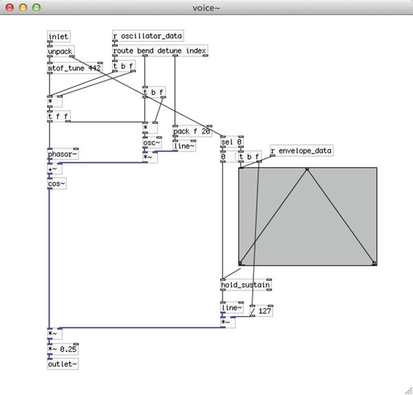
Figure 5-9. The voice~ subpatch receiving pitch bend messages

Figure 5-10. Parent patch receiving pitch bend messages with [bendin]
Polyphony with MIDI in Pd is rather straightforward to achieve, but might seem a bit too much patching, especially if we want to create many voices. One way to reduce the patching is to create the first voice as you want it, test it until you are satisfied with it, and then duplicate it as many times you want. For this chapter’s project, we’re going to use another technique to create many voices: dynamic patching. We’re going to use certain messages to create abstractions (which we will have already made and stored in our system) dynamically without needing to patch everything by hand. We’ll see it in action further on.
Program Change MIDI Messages in Pd
Another type of MIDI message is the program change message. These messages are being sent by MIDI devices with foot switches or pads. In Pd, you can receive these messages with [pgmin]. These messages are single numbers, assigned to a switch or pad. So when you press a foot switch, [pgmin] will output the value of that switch. In the patch we’ve been using so far, there’s no real use of such a message, as it is an on/off kind of message. Later on, when we build the entire project, I’ll mention where this can be helpful, replacing switches used with the Arduino.
This concludes our introduction to MIDI in Pd. We can see that with a MIDI keyboard that includes potentiometers and a pitch-bend wheel, you can create a rather complete synthesizer with Pd. If you want to make it a stand-alone instrument, then the Raspberry Pi (or any other embedded computer) comes in, which we will cover later on in this chapter. Also, not all MIDI keyboards have potentiometers and pitch-bend wheels, and that is where the Arduino comes in, especially if the keyboard has an old-style 5-pin DIN cable. Next is the Arduino code in different versions to include all cases (no potentiometers, 5-pin DIN cable) so you can build a stand-alone synthesizer with any kind of MIDI keyboard.
Arduino Code
Now that we’ve been introduced to MIDI in Pd, let’s see the possible version of the Arduino code that will complement this project. We have three different cases, one where we don’t need Arduino at all, because the MIDI USB keyboard we’re using has potentiometers and a pitch-bend wheel, plus some pads. The second case is a MIDI USB keyboard that’s only that and doesn’t have any potentiometers or anything else apart from the keys. The third case is a MIDI keyboard with a 5-pin DIN cable with no potentiometers; we’re going to use the Arduino for attaching potentiometers and switches, and also for receiving MIDI messages from the keyboard and transferring them to Pd. We’re not going to deal with the first case here, because it doesn’t include an Arduino. I’ll talk about it when we build the Pd patch. So we’ll start with the second case, where we’ll be using the Arduino only with potentiometers and switches. Listing 5-1 shows the sketch. If you are in the third case, go through this section, as including MIDI messages in Arduino will only be complementary to the code in Listing 5-1.
Before I explain the code, we should take a look at the circuit, which is illustrated in Figure 5-11. For now just look at the parts of the circuit and which component connects to which pin on the Arduino. It will help to understand the approach to writing the code in Listing 5-1.

Figure 5-11. Test circuit for synthesizer project
First of all, we can see that now we’re using an Arduino Nano, which we have placed on the breadboard. We have four push buttons patched to the first four digital pins of the Arduino (starting from digital pin 2, as always). Then we have five switches patched to the next five digital pins, and then we have an LED connected to the digital pin 13. We use this pin for the LED so we can avoid an external resistor, which is rather useful when building circuits on perforated boards. The circuit shown in Figure 5-11 is only a test circuit. It’s always a good idea to test your circuit on a breadboard before you attempt to solder it on a perforated board.
On our synthesizer, we’ll have four potentiometers for the two oscillators of each voice, three potentiometers for a filter we’ll apply to the synth, and one potentiometer for the amplitude. The four push buttons will select the waveform for both the carrier and the modulator. The first switch will set whether the push buttons will set the waveform for the carrier, or the modulator, the second switch will control whether we’ll use the filter or not, the third switch will control whether we want to tune our synthesizer, using the [mtof_tune] abstraction, and the fifth switch will control the DSP. The LED will indicate whether the DSP is on or off.
Now that we know what each component of the circuit does, let’s go through the code. We’re using the print function to send data to Pd instead of write. This is mostly because in the next version of the code, where we’ll be receiving data from the MIDI keyboard, we prefer to use this function, because it makes it easy to separate data before they arrive to Pd. The first 25 lines define variables, constants and arrays to read and store data. The comments should make the code rather clear. Notice the offset variable in lines 8 and 9, which will be used along with a for loop, so we can read the correct pins, as we’ve already done. In line 13, we define an array called osc_type_buttons, which will store the values of the push buttons. We group them all in one array, since they are used for the same purpose: to choose a waveform for an oscillator. In line 14, we define another array, called old_osc_type_buttons. This array will hold the previous value of each button, which will be used for comparison when we read these pins, so we can print their values to Pd only when they are changed (actually, when we press a button). You’ll see how this works further on in the code. Lines 15 to 18 define pairs of variables for the pins of the switches in the same manner as with the push buttons arrays. We use two variables—one to hold the current value of each pin and one to hold the previous value—so we can compare them and see if the values have changed. In these lines, you can see that we define two variables in each line, separated by a comma, like this:
int filter_switch, old_filter_switch;
This syntax is perfectly legal in C++, and we use it to make our code a bit more compact and easier to read, since the two variables cooperate. Lines 19 to 25 set pin numbers to variables, which we’ll use to read the switches and write to the LED pin. We could have used the numbers straight in the functions that read and write to pins, but using self-explanatory names makes the code more readable.
The setup and loop Functions
Our setup function is nothing special, we just set the mode of the digital pins we’re using and start the serial communication. This time we’re using a 38400 baud rate, because while testing (including receiving data from the MIDI keyboard, although this should take long) it proved that a higher baud rate stressed the Arduino. In this baud rate, everything works fine. In the loop function, the first thing we do is check for data coming in the serial line, and use that to control the LED of the circuit. This time we’re reading data in a much simpler way than we did before, because the only thing we want to control is one LED, so we don’t need the generic technique we used till now. All we do is create a byte variable to store the incoming data, and write that byte to the pin of the LED. Then we read through the analog pins, which we separate in groups, and afterward we write these values to the serial line. We don’t bother to test whether a value has changed or not, because the analog pins have a little bit of noise and they kind of constantly change, so we print them to Pd anyway.
Now the new part comes in. In line 67, we read the first switch, which sets whether the push buttons will set the waveform for the carrier or the modulator. In line 68, we run a for loop and read through the push buttons. Line 70 checks with an if control structure whether the newly read value is different from the old one, and if it is, its code will be executed. This test will be true whenever we press or release a button. If the value has indeed changed, line 71 will check whether we are pressing the button. We’re using the exclamation mark here, since when we press the button, we’ll read 0 because of the pull-up resistors. Using if this way, its test will be true when the value is indeed zero, since we’re reversing the value by placing the exclamation mark, so when we press the switch, this test will be true. If the test is true, line 72 will test whether the first switch is in the on or off position. This test will be true when the switch is in the off position, because here we’re not using an exclamation mark. If the test is true, we’re printing the i variable to the serial line with the carrier_type tag, and if it’s false, with the modulator_type tag. The i variable will actually hold the number of the switch, since it’s the variable used to control the for loop and goes from 0 to 3. So, if we press the third switch for example, the tests in lines 70 and 71 will be true, and the value we’ll print to Pd will be 2 (we start counting from 0). This way, not only we print a value to Pd only when it’s changed, and more precisely, when a button is pressed, but we also don’t need to print all four switches, but use them all as one entity. Finally, in line 81 we update the element of the old_osc_type_buttons array. If we fail to do this, the test in line 70 will hold true only when we press a switch. This might sound ideal, as this is what we want. What will actually happen is that, while we keep a button pressed, this test will keep on being true, and its code will keep on being executed, so we’ll be printing data to Pd constantly. By updating the variable that holds the old value, we make sure that the test in line 70 will hold true only when the value has indeed changed.
Lines 85 to 90 read the second switch, which is used to define whether we’ll use the filter or not. Again, we’re testing if the value has changed, in line 86, and if it has, we’re printing it with the appropriate tag. We’re using the exclamation mark to invert the value because of the pull-up resistor. We repeat this process for the rest of the switches, each time reading the appropriate pin and using the appropriate tag. And this brings us to the end of the code. It is a rather long sketch, but we’re using the same principle for all digital pins. This technique is very helpful because it facilitates things in Pd to a great extent. Next is the Pd patch, where we’ll see the code and circuit in action, and things will become even clearer.
Pd Patch
Figure 5-12 shows the Pd patch. Most of the stuff is again hidden in subpatches for clarity’s sake. The lower part of the patch should be rather clear. We’re using [notein] with [poly] to receive and diffuse MIDI notes from the keyboard. [poly_synth~] is an abstraction which creates voices according to its argument (in this case 10). We use it this way both for keeping the patch clean, but also because with an abstraction we can automate the process of voice creation so we don’t need to patch each voice separately. We’ll see how this is achieved further on. [pd filter~] contains the filter we’re using in our synth, and after that we have the [dac~] controlled by a potentiometer from Arduino. On the top part of the patch we see [declare -path ./polysynth]. This objects sets a search path exclusively for this patch. If we’re using abstractions that are project specific, and we don’t want to place them in Pd’s standard search paths, we can put them anywhere in our system and use [declare] to set their path for this patch. The -path flag means that what follows is a path. With [declare] we can also import libraries, where we use the -lib flag. The path for our abstractions is located in a directory called polysynth, which is in the directory of the patch, hence ./polysynth. Again, we’re using Unix syntax to specify the path.
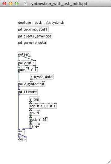
Figure 5-12. Synthesizer Pd patch
The arduino_stuff Subpatch
Now let’s start looking at the subpatches one by one, starting with the arduino_stuff subpatch, which is shown in Figure 5-13. The only different thing here is that we’re sending the DSP value to [comport] as is, without the “print” message, because we’re not assembling the value in the Arduino code, but use the incoming byte as is, so we don’t need its ASCII form here.

Figure 5-13. Contents of the arduino_stuff subpatch
The create_envelope and generic_data Subpatches
Figure 5-14 illustrates the contents of the create_envelope subpatch. Nothing new here as well. Only create the envelope you want and click [dump]. The next time you’ll open the patch, it will be banged on load and will be sent to all voice abstractions.

Figure 5-14. Contents of the “create_envelope” subpatch
Figure 5-15 shows the contents of the generic_data subpatch. Here we receive most of the data from the Arduino. At the top-left part you can see [r carrier_type] and [r modulator_type], which receive a number from 0 to 3 from the Arduino, depending on which of the osc_type_buttons is pressed, and according to the position of the carrier_mod_switch. All this happens in lines 67 to 83 in the Arduino sketch. We can see here that we have done some processing in the Arduino code, and sent the resulting data to Pd instead of only reading the pins, and printed them as is. [r sustain_switch] receives a value straight from the switch that controls whether we’ll hold the sustain of our amplitude envelope or not. On the bottom-left part we receive the value from the DSP switch and control the DSP state accordingly. On the right side of the patch we receive the values from the oscillator potentiometers, which we map and then send to their destinations. [r tune_switch] is there to either let the frequency tune potentiometer through, or not. Since the analog pins have some noise, it’s good practice to not let that value through all the time. We can use the switch that controls this to tune our synthesizer, and when we’re done tuning, we can put the switch in the OFF position, and our tuning won’t be affected any more. Each of these values is being sent to our [poly_synth~] abstraction via [s synth_data].

Figure 5-15. Contents of the “generic_data” subpatch
Now let’s look at the [poly_synth~] abstraction, which is shown in Figure 5-16. There are quite some new things here, which I’ll explain in detail. This is a rather simple abstraction, but it facilitates polyphony a great deal. It has three control inlets and one signal outlet. The control inlets send their data to various destinations using [send]. Notice the $0 used in each [send], and in the name of the two subpatches. This is a special sign in Pd. When we use it in abstractions it generates a unique number, usually starting from something over 1000, which is used to create unique names for objects like [send]/[receive], or for arrays and [table]s. If we want to create more than one instance of this abstraction, and we didn’t use $0, whatever would arrive in an inlet of any abstraction, would be sent to the corresponding [receive]s of all instances of the abstraction. Using $0 we make sure that whatever arrives in an inlet of an instance of the abstraction, will be diffused only locally to that specific inlet. For example, if we created two [poly_synth~] abstractions, $0 of the first would be something like 1009, and of the second something like 1013. When data arrived in the first inlet of the first abstraction, it would be sent to [s 1009-voice-list], and would be received by all [r 1009-voice-list], which would exist in the first abstraction only, so this data wouldn’t be received in the second abstraction as well. If we sent data to the first inlet of the second abstraction, it would be sent to [s 1013-voice-list] and would be received by [r 1013-voice-list], without interfering with [r 1009-voice-list] at all.
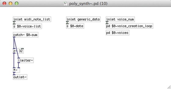
Figure 5-16. [poly_synth~] abstraction
The [pd $0-voice_creation_loop] subpatch
We cannot see this unique this unique number printed, but wherever in the abstraction you see $0, it is actually replaced by this unique number. [pd $0-voice_creation_loop] demonstrates its use clearer. Its contents are illustrated in Figure 5-17.

Figure 5-17. Contents of the “$0-voice_creation_loop” subpatch
This subpatch is banged on load with [loadbang], which bangs [$1 ]. [$1 ] takes the value of the first argument of the abstraction. In Figure 5-12, which illustrates the main patch for this project, we can see that we have initiated [poly_synth~ 10] with the argument 10. This is the value [$1 ] will take, which is the number of voices we want to create. When this value is banged, it first bangs the message “clear”, which is sent to [s pd-$0-voices]. This [send] sends its data to the “$0-voices” subpatch you see in Figure 5-16. By using the name of a subpatch with “pd-” prepended to it, we can send data directly to the subpatch. The message “clear” will erase everything in the subpatch. Then a loop will be initiated with 10 iterations (due to the argument provided to [poly_synth~]) using the [loop] abstraction. At each iteration of the loop, the incremented value coming out the rightmost outlet of [loop] will first be multiplied by 30 and added to 30. It will be stored to the middle inlet of [pack f f $0], and then added to 1 and stored to the leftmost inlet of [pack f f $0]. This will cause [pack] to output its values, because the leftmost inlet is hot. The last value of [pack], which is $0, will be the unique value generated by $0, as already mentioned.
The list output by [pack] goes to the message “obj 100 $2 synth_voice~ $3 $1”. This message is sent to [s pd-$0-voices], hence to the “$0-voices” subpatch. Sending a message of this type to a patch (or subpatch) will create an object, much like putting an object from the Put menu, or by hitting Ctrl/Cmd+1. This specific message will create the object [synth_voice~] with two arguments, the third and first values output by [pack] ($3 and $1 in the message), positioned at 100 pixels to the right and $2 (the second value of [pack]) pixels down. As the loop iterates, $2 will take the following values: 30, 60, 90, and so forth (remember, [loop] starts counting from 0). So the [synth_voice~] objects that will be created, will be placed at the following coordinates in the “$0-voices” subpatch: 100 30, 100 60, 100 90, and so forth. This means that the objects will be placed one below the other, all aligned at vertically. The two arguments each [synth_voice~] will take, are the unique number of [poy_synth~], and the number of each voice, starting from 1. So the objects that will be created inside [pd $0-voices] will be [synth_voice~ 1009 1], [synth_voice~ 1009 2], [synth_voice~ 1009 3], and so forth, given that the unique number generated by $0 is 1009.
How Dollar Signs Work in Pd
The dollar-sign numbers in Pd are very useful and it’s important that you understand them. In objects, like [$1 ], dollar-sign numbers starting from 1 take the value of the corresponding argument in an abstraction. So [$1 ] will take the value of the first argument, [$2 ] will take the value of the second argument, and so forth $0, as already mentioned, generates a unique value for abstractions (for subpatches too, but it behaves a bit differently there), which is used to avoid name clashes with [send]/[receive] pairs and [table]s and arrays. In messages, dollar-sign numbers take the corresponding value from an incoming list. So, when the list “6 13 27 9” comes in the message “$1 $2 $3 $4”, $1 will take the value 6, $2 will be 13, $3 will be 27, and $4 will be 9. Messages cannot take values directly from arguments, but only from lists that arrive in their inlet. Also $0 won’t work with messages. That’s why in Figure 5-17, we store $0 in [pack] and send it to the message, which is retrieved by the message’s $3. Dollar-sign numbers might be a bit confusing in the beginning, but once you get the grasp of it, you’ll see how powerful this feature is.
The [synth_voice~] Abstraction
In [poly_synth~], create a subpatch called “$0-voices”, like in Figure 5-16, and leave it empty. That’s where all the [synth_voice~] objects will be created. Of course [synth_voice~] is no native Pd object, but another abstraction we’ll create ourselves. You can see the abstraction in Figure 5-18.

Figure 5-18. The [synth_voice~] abstraction
At the top part of the patch we have a [r $1-voice-list], which will receive values from [s $0-voice-list] of [poly_synth~]. Since we’ll be creating the [synth_voice~] as described earlier, the first argument of this abstraction will be the unique number generated by $0 of the [poly_synth~] abstraction. We cannot use $0 straight in [synth_voice~] because it will generate a new unique number which won’t be the same with that of [poly_synth~], plus every instance of [synth_voice~] will get its own unique number, and now we don’t want that, since we want to send the same data to all voices. All $1 values in Figure 5-18, will be the same as $0 in Figures 5-16 and 5-17.
On the right part of the abstraction we receive data with [r $1-data], which is diffused with [route]. The leftmost outlet of [route] will output the tuning frequency for our synth, the second outlet will output the oscillator type for the carrier oscillator, and so on. The arguments of [route] should make clear what each value does (don’t hit Return after the “index” argument, just type all the arguments with spaces between them. When they become too many to stay in one line, Pd will start printing them one line below by itself).
[r $1-voice_list] sends its list to [route $2], which will give its output according to the second argument of [synth_voice~], which is the voice number. When [poly] in the parent patch (Figure 5-12) outputs the list “1 69 127”, [route $2] of the first [synth_voice~] will output the list “69 127”. [route $2] of the rest of the [synth_voice~] abstractions won’t output anything, because the first element of the list “1 69 127” won’t match their argument.
The list coming from [route $2] in unpacked and the note number is sent to [mtof_tune 442], which will convert the note number to its frequency, tuned at 442 Hz. The velocity (the second element of the list output by [route $2]) is sent to [sel 0], like with the MIDI examples earlier in this chapter. The main structure of this abstraction is very similar to the subpatches of the MIDI examples, where we apply phase modulation and we use an amplitude envelope. This time we can choose between different waveforms for both the carrier and the modulator. The “modulator” subpatch in Figure 5-18 is shown in Figure 5-19. And the contents of each subpatch in [pd modulator] is shown in Figures 5-20 to 5-23.

Figure 5-19. Contents of the “modulator” subpatch of the [synth_voice] abstraction

Figure 5-20. [pd sinusoid]


Figure 5-23. [pd square]
The modulator Subpatch and Its Subpatches
When [synth_voice~] receives the message “mod_type $1”, it sends this value to [pd modulator], and from there it goes to the subpatches in Figures 5-20 to 5-23. In these figures each [sel] will control the [switch~] of each subpatch. [switch~] enables turning the DSP of a subpatch or abstraction on or off, independently of the DSP state of Pd. This helps us both to choose the oscillator type we want, but also to save some CPU since we have four oscillators for the modulator and four for the carrier of each voice, eight in total, for ten voices, which makes them 80! If we want to use more voices then the oscillators we’ll be using will start becoming a bit too many. Using [switch~] reduces the amount of CPU Pd needs drastically. We’ve also used [switch~] in the parent patch of [synth_voice~], the use of which I’ll explain in a bit.
[synth_voice~] also has a [pd carrier], which sets the oscillator for the carrier. This subpatch is almost identical to [pd modulator], only [phasor~] is outside the subpatch so we can modulate its phase. Figure 5-24 shows the subpatch. This subpatch has a signal inlet for the oscillators, which first connects to [wrap~]. This object wraps the value in its input between 0 and 1. So if it receives 1.1, it will wrap it back to 0.1. If it receives –0.1, it will wrap it back to 0.9. Check its help patch for more information. We’ve put it there because we add the modulator oscillator to the phase of the carrier. The phase must always be between 0 and 1, whether it is modulated or not. When we built the MIDI examples earlier in this chapter we didn’t use [wrap~] because we used a cosine oscillator with [cos~], and [cos~] wraps the values it receives internally, so we didn’t need to do this explicitly. This time, though, we use more oscillators which consist of objects that don’t wrap their input internally, so we must use [wrap~] to avoid strange results. The subpatches of [pd carrier] are identical to those of [pd modulator], as shown in Figures 5-20 to 5-23.

Figure 5-24. Contents of [pd carrier]
Now I’ll explain the bottom-left part of [synth_voice~] where we have the amplitude envelope plus some other things. In the middle part of Figure 5-18, we see a [sel 0] that receives the velocity of the MIDI note, and connects to [t f b], which first outputs a bang out its right outlet, which goes to [t b b]. This last [trigger] first bangs [f ], which takes its value from “duration” from the [route] above it. This value is the duration of the envelope, which also goes to the message “duration $1” and is sent to [ggee/envgen] to set this duration to the envelope. The output of [f ] goes through [spigot], and if [spigot] is open, it goes to the left inlet of [del]. “del” stands for delay, and it’s a delay object for the control domain. It is somewhat different from the signal domain delay. It receives a value and it outputs a bang delayed by the value it received, in milliseconds. Check its help patch for information. When [del] receives the duration amount in its inlet, it will send a bang out its outlet after the set delay, which will send 0 to [switch~]. The left outlet of [t b b] sends 1 to [switch~], which means that the abstraction will turn its DSP on. After all this is done, [t f b] will send the velocity out its left outlet to a [t b f], which will first output the velocity from its right outlet and it will go to [/ 127] at the bottom part of the patch. Then [t b f] will output a bang from its left outlet, which will trigger the envelope.
The gate Subpatch, How It Works, and How We Manage the Audio of [synth_voice~]
Below [ggee/envgen] there’s [pd gate], which we can see in Figure 5-25. This subpatch takes the output of [ggee/envgen] in its left inlet, and the “sustain” value from [route] in its right inlet. This value is either a 1 or a 0, controlled by the sustain switch in the Arduino circuit. It sets whether we’ll hold the sustain part of the envelope as long as we keep the key pressed, or not. If the “sustain” switch value is 0, then the output of [ggee/envgen] will connect straight to [line~]. If it’s 1, it will connect to [hold_sustain] and then to [line~]. The “sustain” switch value also controls the [spigot] after [f ] in the parent patch of the abstraction, which holds the duration of the envelope. If the “sustain” switch is off, then the [spigot] will be open (because of [== 0]), and if it’s on, [spigot] will be closed. If we keep the “sustain” switch off, then [switch~] will receive 1, the envelope of [ggee/envgen] will be triggered, when after the duration of the envelope has ended, [switch~] will receive 0 banged by [del], since [spigot] will be open. If the “sustain” switch if on, then [switch~] will receive 1, the envelope will be triggered, but [spigot] will be closed, so [del] won’t receive the duration value from [f ], but [hold_sustain] will output the appropriate delay time out its right outlet when it receives 0, and [switch~] will be closed when it should. Check the help patch of [hold_sustain] to see how this works.

Figure 5-25. Contents of the “gate” subpatch
Each [synth_voice~] sends its output to [throw~ $1-sum], which all go to [catch~ $0-sum] in [poly_synth~], in Figure 5-16. The output of [catch~] is controlled by [limiter~]an external of the zexy library— to make sure we’ll never exceed an amplitude of 1. We could have multiplied the output of each [synth_voice~] by the reciprocal of the number of voices, but using [limiter~] gives a better result, as if we play only one voice, it will have full amplitude, instead of one-tenth (in the case of 10 voices) of it. Check the help patch of [limiter~] to see how it works.
Now that we’ve discussed and built [poly_synth~] and [synth_voice~], let’s go back to the parent patch of our project, the one shown in Figure 5-12. There’s one subpatch left to show and discuss: filter~. It is shown in Figure 5-26. Compared to all we’ve already done, this should be fairly easy. It receives the output of [poly_synth~] and sends it both to its [outlet~], intact, but also to [omniFilter_abs~ lowshelf]. [omniFilter_abs~] is an abstraction for many types of filters. The filter type is sent via an argument (or from the rightmost inlet; check its help patch). [r filter_pots] receives the filter potentiometer values from Arduino, and [r filter_switch] receives the value of the filter switch of the Arduino circuit. If the switch is in the OFF position, the input of [pd filter~] will be output intact. If it the switch is in the ON position, the input will go through [omniFilter_abs~]. The output of [pd filter~] is being sent to [dac~] having its amplitude controlled by the last potentiometer of the Arduino circuit.

Figure 5-26. [pd filter~]
Done with Patching, Time to Test
We have now completed the Pd patch for this project. If your MIDI keyboard doesn’t have a USB cable, the modifications to the patch will be minor, and we’ll go through them in a bit. Now close the patch and re-open it, click [poly_synth~] and check [pd $0-voices]. This subpatch should look like Figure 5-27.

Figure 5-27. Contents of [pd $0-voices]
In the title bar of the window, you should see something like 1045-voices. 1045 is the unique number created by $0 (yours is very likely to be different), so this title is the result of “$0-voices”. The number in the parenthesis is the argument passed to [poly_synth~], which appears on the title bar of all subpatches of the abstraction. Using $0 in [pack f f $0], in [pd $0-voice_creation_loop] results in creating all [synth_voice~] abstractions with this unique number as the first argument. It doesn’t really matter what your unique number is. What is really important is that the number on the title bar of [pd $0-voices] should be the same as the first argument of all [synth_voice~] abstractions; otherwise, things are not going to work properly. The second argument of [synth_voice~] is the voice number, and it should be an incrementing number starting from 1.
Building this project with all the subpatches, and especially with the abstractions, might be a bit complicated, but if you build the abstraction carefully, and go through the explanations (maybe more than once) you should be able to understand how everything works. Pd, being a visual programming language, projects the data flow very clearly, so it’s easy for you to follow the data from beginning to end, or the other way round, to understand how a patch works. You should first have a good understanding of the Arduino circuit and code, and what each component is supposed to do, and then apply this to the Pd patch and abstractions, so you can fully understand their behavior.
Arduino Receiving MIDI Messages from the MIDI Keyboard
In case you have an old MIDI keyboard that has a 5-pin DIN cable, you’ll need to do some tweaking to the code and circuit to be able to use it with the Raspberry Pi. If you intend to build this project with a laptop (or a desktop), and you have a MIDI-to-USB converter, or you have an external sound card that takes MIDI cables, then you don’t need to go through this section, except if you’re just curious.
Figure 5-28 shows a female MIDI connector. If you connect one end of a MIDI cable to your keyboard and the other end to such a connector, then you’ll have easy access to it pins. You might need a multimeter to make sure you connect to the right pins. This device is very useful when building electronics, so it’s advisable to get one. Learning how to use it is rather easy, and there are a lot of resources online. To build the circuit you’ll also need an optocoupler. This is a very small, inexpensive chip that will help the circuit work. I have used the 4N35 optocoupler, but the 4N28, or probable any from these two families would do. Instead of building the circuit yourself, you could get an Arduino MIDI shield that exists on the market, but building such a circuit will cost very little money (probably less than one dollar), and can also be fun to do.
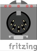
Figure 5-28. Female MIDI connector
Arduino Circuit Additions
Figure 5-29 shows the additional circuit we’ll need to receive MIDI messages from our keyboard. The previous circuit still holds, the one in Figure 5-29 is supposed to be added on top of the previous circuit. There could be other ways to achieve this, but I found that this one was rather simple and used components I had lying around, so it took me very little time to build it. You are encouraged to search yourself to find other solutions for this, but the circuit in Figure 5-29 should do the trick.

Figure 5-29. Connecting a MIDI cable to Arduino
In this circuit, we’re connecting MIDI pin 4 (the second from right) to the first pin of the optocoupler, via a 220Ω resistor. The first pin of the optocoupler is marked with a dot (some chips might only have a notch on one side, where having that side on top, the top pin on the left side is the first pin of the chip), and the rest are numbered sequentially. Figure 5-30 shows the pin numbers of 4N35. All chips follow the same numbering order. The second pin of the optocoupler connects to MIDI pin 5 (the second from right, MIDI pins are not numbered sequentially), and also to the first pin of itself via a 1N4148 diode, with the ring of the diode on the side of the first pin of the chip. Pin 4 of the optocoupler connects to ground, pin 5 connects to 5V via a 3K3 resistor (3K3 notation means 3.3KΩ) and to Arduino’s digital pin 11. Finally, pin 6 of the optocoupler connects to ground via a 100K resistor.

Figure 5-30. Pin numbering of 4N35 optocoupler
Arduino Code Additions
The code in Listing 5-1 stays, and we’re just going to add a few things to it, so it can receive MIDI messages and transfer them to Pd. First of all, at the beginning of the code type the contents in Listing 5-2.
As with the Bluetooth module from Chapter 3, where we needed an extra serial line to configure it, we’re going to need another serial line now to receive data from the MIDI keyboard. To do this, we need to import the SoftwareSerial library and create an object with two pins, an RX (for receiving data) and a TX (for transferring data). We’re going to use only the RX pin, since we won’t be sending any data to the MIDI keyboard, but when we initialize an object of the SoftwareSerial class we need to include both pins. Then we’ll need to define two variables, one for the MIDI note number and one for the velocity.
Then in the setup function we must start the serial communication of the new, SoftwareSerial port. Listing 5-3 shows what you should type in the setup function.
The baud rate used here is the baud rate of the MIDI protocol. We need to use that to be able to communicate with the MIDI keyboard. The baud rate we’re using for the communication between the Arduino and Pd is (Serial.begin(38400);), it doesn’t need to be the same (actually [comport] doesn’t support this baud rate), so you can still use 38400. Lastly, Listing 5-4 shows what you should write in your loop function.
This can go anywhere in your code, I put it right after reading data from the serial line, in the beginning of the loop function. What happens here is that we’re checking if there are data in the serial port of the MIDI, and if there are, we read them. In the MIDI protocol, the first byte that is sent is called a status byte, which tells the receiving device what kind of command it is receiving, and the rest of the bytes are called data bytes, which hold the data of the command. What we care about is the note-on and note-off messages. These messages are 144 for note-on on channel 1, 145 for note-on on channel 2 and so on, for sixteen channels, so from 144 to 160. 128 is note-off for channel 1, 129 is note-off for channel 2 and so forth, for sixteen channels, so from 128 to 143. So line 3 in Listing 5-4 checks if we’re receiving a note-on message (we don’t really care about the channel). If it’s true it will assign the next two bytes to the MIDI_note and MIDI_velocity variables, respectively, because this is the order these data bytes are sent. Then we print these two values to the serial line Pd is listening to with the MIDI_note tag, including a space in between values so they can be properly interpreted by the [serial_print] abstraction.
Line 12 checks if we’re receiving a note-off message, and if it’s true, it will execute the same code with the note-on message. Again, what we care about is the note number and the velocity. Of course, the note-off velocity is zero, so this is kind of trivial. Many MIDI keyboards don’t even send note-off messages, but instead they send a note-on message with a 0 velocity. Even if that’s the case with your keyboard, this code should work. Again, we print the data bytes to Pd’s serial line with the MIDI_note tag. You can imagine that in Pd we’ll be receiving this data with [r MIDI_note].
Mind that all this code is added to the code we’ve already written for the Arduino, nothing should be replaced by anything (including Serial.begin(38400);).
Your keyboard might also send control messages, which are indicated by the status bytes—176 up to 190, again for 16 channels. The data bytes that follow are the controller number and the controller value. The keyboard I have doesn’t send control messages, so I can’t test it. Applying the values of control messages to the code in Listing 5-4 should be fairly easy, and printing these values to Pd, are receiving them there should also be rather easy. If your keyboard sends control messages, you’re encouraged to modify your code to receive them in Pd.
The basic status bytes, along with their values, can be found at http://www.midi.org/techspecs/midimessages.php.
You can test if your keyboard sends any of the status bytes in Table 5-2. All the status bytes in the table are followed by two data bytes, except from program change and channel pressure, which are followed by one data byte only. Make sure you read all data bytes in your Arduino code.
The pitch bend change status byte is followed by the 7 bits of the least significant byte, and the 7 bits of the most significant byte. To assemble these two bytes in Pd, you’ll need to multiply the first byte (the least significant byte) by 128, and add it to the second byte (the same technique we apply with the [serial_write] abstraction to reassemble the analog pin values from the Arduino). This will yield a maximum value of 16383, which is the 14-bit value of the Pitch Bend wheel on MIDI keyboards.
To determine what data your MIDI keyboard is sending, [print] will come in handy in Pd. This object prints whatever it receives in its inlet to Pd’s console. Replace the code in Listing 5-4 with that in Listing 5-5 to determine what kind of data your keyboard is sending.
In a Pd patch connect [r MIDI_data] to [print] and use all potentiometers and wheels and other controllers on your keyboard. [print] will print to the console anything it receives. Use Table 5-2 to determine what kind of data you’re receiving, whether it’s Note On/Note Off events, Control Change, or Program Change messages, and so forth. For example, if you’re receiving a Control Change message on channel 1, from controller number 8, sending the value 100, in Pd’s console you should get the bytes 176, 8, 100 one after the other. It’s up to you how you use this information.
Pd Patch Receiving MIDI Data from Arduino
Once you’ve built the circuit and modified the Arduino code, you should make a very small modification to the Pd patch. The patch is shown in Figure 5-31. The only actual change is that [notein] has been replaced by [r MIDI_note], which sends its list to the left inlet of [poly], which is the same as sending the velocity to the right inlet and the note number to the left, like we did with [notein].

Figure 5-31. Pd patch receiving MIDI data from the Arduino
Pd Patch Receiving a Constant Velocity
Some MIDI keyboards may be so old that they won’t really send a velocity value, because their keys might not be force sensitive. This is the case with my MIDI keyboard, which instead of a velocity, on a key press it sends the value 64 as velocity (which I found out by connecting [r MIDI_note] to [print]), and on a key release it sends the value 0, both with a Note On event. In this case unfortunately you won’t have amplitude control with the key presses, but you can still use your keyboard. What I’ve done is send a 127 with a note-on, and let the 0 through. The patch is shown in Figure 5-32. I use [sel 64], so that whenever I press a key and get 64, I send 127. When [sel 64] receives 0 it will let it through intact out its right outlet. This minor modification to the patch in Figure 5-31 seems to fix the constant velocity problem.

Figure 5-32. Pd patch receiving a fake velocity
This concludes our programming for this project, now we’re going to use the Raspberry Pi to embed it to our keyboard to make it a stand-alone instrument.
Running the Pd patch on Raspberry Pi
If you want to embed a computer to your keyboard, so it’s a stand-alone instrument, you’ll need to use a Raspberry Pi, or any other embedded computer you like. Most of the process should be clear by now, there are a few things that I should explain. First of all, copy the Pd patch and the Arduino sketch to your embedded computer using SCP, like we did in Chapter 3. Since the Pd patch contains a folder with the abstractions, you’ll need to copy this whole directory (the one that contains the patch and the polysynth folder) to your embedded computer. Also, the Arduino sketches must be inside a directory with the same name as the sketch, so again you’ll need to copy a whole directory. Use scp -r /path/to/directory to copy the whole directory. The commands for copying to Pi’s pd_patches and sketchbook directories are shown next. Replace /path/to/... with the actual path of the directory with the Pd patches and the Arduino sketch.
scp -r /path/to/pd_patch/directory/[email protected]:/home/pi/pd_patches

scp -r /path/to/arduino_code/directory/[email protected]:/home/pi/sketchbook
You’ll also need to copy any abstractions we used that are not in the polysynth folder, which is in the folder of this project, like [loop], [map], and maybe [hold_sustain]. The best thing to do is to copy the contents of pd_abstractions folder from your computer to Pi’s pd_abstractions, and set that directory to Pd’s search path.
Since we’re going to use the Pi headless (or any other embedded computer), we want to force it to launch Pd and the synthesizer patch on boot. The process differs between the Raspbian Jessie and the Raspbian Wheezy images, and very likely between the Raspbian Jessie image and a Debian Jessie image on another type of embedded computer. First, we’ll cover the Raspbian Jessie procedure.
Launching Pd on Boot with the Raspbian Jessie Image
In your home directory, create a directory named my_scripts. Go to that directory and type the following:
nano launch_pd.sh
The nano editor will open. In it, type the following:
#!/bin/sh
/usr/bin/pd -nogui -open /home/pi/pd_patches/synthesizer/synthesizer.pd &
Hit Ctrl+O and Return to save the file and Ctrl+X to exit nano. You have now created a script that launches Pd in the background without the GUI and opens the synthesizer patch. The first line of the script tells the shell which program to use to interpret the script. The third line (the second line is blank) is the command that launches Pd.
Now, being in your home directory, type the following:
crontab -e
This will open the crontab file of the user pi. If it’s the first time you run the crontab editor, you’ll be asked which editor you want to use to edit crontab, while being prompted to use nano, as it’s the simplest one. The choices will be numbered, and nano will probably be the second choice, so type 2, and hit Return. The crontab file will open in nano and you’ll be able to edit it.
If you haven’t edited this file it should only have a few lines with comments, telling you what this file does and how to use it (well, giving some minimal instructions). After all the comments add the following line:
@reboot sleep 20 ; sh /home/pi/my_scripts/launch_pd.sh
This tells the computer that when it reboots (or boots) it should first do nothing for 20 seconds, and then it should run the script we’ve just written. Take care to place the semi-colon between the sleep 20 command and the sh command. You might want to experiment with the number 20, and try a smaller number. Give the Pi enough time to fully boot, but 20 might be too much. Try a few different values and see which is the lowest that works.
Launching Pd on Boot with the Raspbian Wheezy Image or with Another Embedded Computer Running Debian Jessie
Linux systems include a script that runs on boot (this holds true for the Raspbian Jessie image, but it won’t work), so we can use that to tell the computer to do what we want it to do. This script is in the /etc directory and it’s called rc.local. In your home directory (or wherever), type the following:
sudo nano /etc/rc.local
This sketch by default looks like Listing 5-6.
This is what it looks like in a Raspberry Pi. Maybe it will be a little bit different on some other embedded computers, but essentially it does the same thing, run on boot. We shouldn’t care about what these lines do, it’s not of our interest. Before exit 0 we’re going to write a command to launch Pd along with the patch we want. The command you need to place there is shown here:
su -c ’/usr/bin/pd -nogui -open /home/user/pd_patches/synthesizer/synthesizer.pd &’ - user &
This command tells the computer to launch Pd without the GUI, and open the synthesizer patch (here we suppose that the patch is called synthesizer.pd that is in the directory called synthesizer in the pd_patches directory in the computer’s home). There seems to be an issue with [comport], which doesn’t like to be used by root. su is the name of the root, and since we’re using a script in the / directory, we must have root privileges. The -c flag tells the computer to run the command inside the single quotes as the user set after the single quotes close. This means that you must replace the word user with the name of the user, where in the Raspberry Pi it’s pi, in the Odroid it’s odroid, in Udoo’s Debian images it’s probably debian, and so forth. To find the name of the user, type the following:
$ whoami
The user name will be printed in the terminal monitor. The command in the /etc/rc.local script will result in Pd being launched by the “user” user, and not by root (again “user” refers to the name of the user). This way the patch will open and [comport] will run just fine. We’re launching Pd in the background, and the command that tells the computer to do this as user user, by using the ampersand (&) in both commands. Use this command as is if you want things to run properly. After you type the command in the script, hit Ctrl+O and Return to save it, and Ctrl+X to exit nano.
Mind that it’s not definite that editing this script will work. If it doesn’t, try the procedure of the Raspbian Jessie image explained earlier.
Using a USB MIDI Keyboard with the Pi
If you have a USB MIDI keyboard that you want to use with the Pi there are a few more steps you’ll need to take. First, you’ll need to launch Pd with the -alsamidi flag with the GUI. Once launched open a new patch and put a [r pd] connected to a [print]. Then go to Media ä MIDI Settings... and make sure you have one In Port:. If you changed the number of ports, click Apply. Whether you changed the ports number or not, click OK. In Pd’s console you’ll get a message of the type “midi-dialog 0 0 0 0 0 0 0 0 1 1” (not necessarily the same). Copy this message and paste it in a message box in your synthesizer patch. Connect a [loadbang] to the message and the message to [s pd], like in Figure 5-33.

Figure 5-33. Sending the MIDI dialog message to Pd on launch
Now, on Pi’s terminal, type the following and check the output:
aconnect -lio
Your USB MIDI device and Pd should be in that list. In the script that launches Pd, after launching it write the following:
sleep 3
aconnect yourUSBmidiDevice:0 ’Pure Data’:0
Change yourUSBmidiDevice with the name of your MIDI keyboard. The two 0s are the output port number of the MIDI keyboard and the input port number of Pd. The output list of aconnect should print the correct values. Check Chapter 1 if you don’t remember the exact process of getting MIDI input in Linux.
Shutting Down the Pi (or Any Embedded Computer) While Running Headless
If we’re going to use Pd without the GUI, we’ll need to be able to shut the Pi down somehow. We have used all pins of the Arduino, so we can’t put another push button that will enable shutting down the Pi. We have to use the existing components in some way that will help us achieve what we want. The most logical thing is that when we’ll want to shut the Pi down, we’ll have turned the DSP off. We can use the DSP switch to determine whether we can actually shut the Pi down or not. In the Arduino code add the code in Listing 5-7 to the end.
This code will run only if the DSP switch is in the OFF position (because of the pull-up resistors). If the switch is indeed off, we’ll read digital pin 2, which is the first push button, and we’ll print that to Pd with the shut_down tag. In the Pd patch, make a subpatch and fill it in with the contents in Figure 5-34.

Figure 5-34. Contents of the subpatch that shuts the Pi down
In this subpatch we’re receiving the value of the first push button, only when the DSP switch is in the OFF position. We’re printing the value of the button with the exclamation mark prepended to it (line 4 in Listing 5-7), so that when we press it we’ll receive a one, and when it’s released we’ll receive a 0. We’re using [timer] in this subpatch, which measures logical time. When this object receives a bang in its left inlet, it is reset. When it receives a bang in its right inlet, it outputs the amount of milliseconds passed since it was reset. We’re sending the output of [timer] to [> 2000] to check if we held the button pressed for at least 2000 milliseconds (2 seconds). Think about it, when we press the button (with the DSP switch in the OFF position), [timer] will be reset, and when we release it, we’ll get the amount of milliseconds we kept the button pressed. If this value is above 2000, [> 2000] will output 1, and [sel 1] will bang the message, which will tell [shell] to run the script to shut the Pi down. This is the same script we wrote in Chapter 3, so if you skipped that chapter, go back and check it. [change] connects to [spigot], which opens two seconds after the patch has loaded, to prevent a shut down as soon as the patch opens, as the code in 5-7 will be printing the value of the first button constantly, as long as the DSP switch is in the OFF position.
A Small Caveat for the Raspbian and Debian Wheezy Images
If you’re using the Raspbian Wheezy image, or another embedded computer with a Debian Wheezy image, you should have noticed that you can’t make [serial_print_extended] work. That is because it’s missing the [bytes2any] and [any2bytes] externals from the moocow library. The Raspbian repositories don’t have this library so we haven’t installed it. Go to GitHub and search for pdstring. Once you find it, download it as a .zip file. In your Pi, make a directory called pd_externals and move the pdstring-libdir-master directory in there (the directory you unzipped from GitHub). Now navigate to pdstring-libdir-master and hit ls to see its contents. There are three README files, which include instructions for installing the new externals. The instructions say that you must type ./configure, but there’s no configure file there. All you need to do is this:
make
and
sudo make install
First, run the make command, which will create binary files (executable files) out of the .c files, and when it’s done (you’ll get back to the $ prompt) run the second command. This will put the new binary files to /usr/local/lib/pd-extenals/pdstring. Now launch Pd and go to Media ä Preferences ä Path and choose this path so Pd can look up for these objects. Click Apply and OK and quit Pd. Re-launch it and open a new window and put [serial_print_extended]. You’ll get error messages saying that Pd couldn’t create [moocow/bytes2any] and [moocow/any2bytes]. Open the [serial_print_extended] abstraction and go to [pd $0-strings]. In there, change [moocow/bytes2any] to [bytes2any]. Then go to [pd $0-set_argument] in the parent patch of the abstraction, and from there to [pd $0-split_symbols]. In there, change [moocow/bytes2any] to [bytes2any], and [moocow/any2bytes] to [any2bytes]. Close the subpatches and save the abstraction. The next time you open it, it should work. I should mention that these are not my externals. I have only forked the repository in GitHub, so you can easily find these files.
Using an External Sound Card with the Pi
If you have an external sound card you want to use, you might need to take some steps to use it. I’ll suppose that it either doesn’t require drivers, or that you already have installed all necessary drivers for it. In Pd, you can go to Media ä Audio Settings... and choose your sound card. That might not work though, and you might either get audio dropouts (they produce clicks in the sound), or perhaps no audio at all. When using external sound cards in Linux, many time we prefer to use the Jack audio server. If the Pi doesn’t have Jack installed, you can install it with apt-get. In Pi’s terminal type jackd, and if you get a “command not found” error, then type sudo apt-get install jackd.
Using QJackctl offers an easy way to find out which is your sound card on Jack’s list. This is a user-friendly GUI version of Jack. In Pi’s terminal, type the following:
/usr/bin/qjackctl &
QJackctl will open, as shown in Figure 5-35. Make sure that you use the ampersand (&), because we’ll need to use the terminal while QJackctl is running.

Figure 5-35. QJackctl interface
In QJackctl click Setup and you’ll get the window shown in Figure 5-36. In the Setup, click the Input Device: menu and select your sound card. Figure 5-37 shows some choices provided by QJackctl, where a Focusrite Scarlett 2i4 sound card is included. What we care about is its hw number (for hardware), which is 1. Go ahead and choose your sound card both as an input and as an output device, and then click OK (leave Driver: on top right at “alsa”). This will take you back to the main window of QJackctl, as shown in Figure 5-35. Click Start and wait till the QJackctl screen shows that it has started.

Figure 5-36. Qjackctl’s setup

Figure 5-37. QJackctl sound card choices
Now go back to Pi’s terminal and launch Pd like this:
/usr/bin/pd -jack &
This command will launch Pd in the background with Jack as its audio server. Go to Media ä Test Audio and MIDI... and see if your sound card is working properly. If it is, quit Pd, and click Stop on Qjackctl’s window, and then Quit.
Since we’ll be using the Pi headless, we can’t use Jack’s GUI, so we need to launch it without it. In Pi’s terminal, type the following:
/usr/bin/jackd -d alsa -d hw:1 &
This will launch Jack, using Alsa as a driver and a hardware 1 sound card. Now launch Pd like before and again test if your sound card is working properly. If all goes well, you’ll need to modify the scripts that launches Pd a bit. Open ~/my_scripts/launch_pd.sh and before the command that launches Pd, type the following:
/usr/bin/jackd -d alsa -d hw:1 &
sleep 3
This will launch Jack with the necessary driver and sound card, and then the Pi will wait for three seconds, before it launches Pd. The command to launch Pd stays the same. If you’re using another embedded computer or the Raspbian Wheezy image, you’ll need to add these two lines in the /etc/rc.local script, before the command that launches Pd. No need to run this command as a simple user, so the command will do just the way it’s written earlier. Now edit the script that quits Pd and shuts the Pi down. Type the following to edit the script:
sudo nano /etc/my_scripts/shut_down.sh
We want to first quit Pd, then Jack, and then shut the Pi down. We already have this in our script:
sudo killall pd
sleep 3
sudo halt
Change it to this:
sudo killall pd
sleep 3
sudo killall jackd
sleep 3
So now the Pi will first quit Pd, then wait for three seconds, then it will quit Jack, again it will wait for three seconds, and finally it will shut down. Now your Pi is ready to run your patch using your external sound card.
Editing the Pd Patch When Pd is Running on Boot
Once you have configured your Pi with the settings we’ve been through, whenever your power it up, it will launch Pd and open the synthesizer patch. If you want to make changes to the patch, or use the Pi for something else, as soon as you log in, quit Pd like this:
sudo killall pd
so you there’s no Pd instance running while you make your changes. If you need to quit Jack as well, do the same for “jackd”. If you make changes to the already used patch, you won’t need to do anything else. If you want to use another patch, or do something completely different, you’ll have to edit at least the rc.local script, so that the Pi won’t launch Pd, or won’t open the old patch on boot.
Enclosing the Pi in the Keyboard
To enclose the Pi in the keyboard so that it’s a stand-alone instrument is a process of trial and error. Since all keyboards are different in size and shape, I can’t give definite guidance through this process. There are some “global” rules that apply to such processes. Bear in mind that most electronic devices have very limited space inside, so it might be very difficult or even impossible to enclose the circuit, the Arduino and the Pi inside your keyboard. In this case, you might want to enclose all this stuff in a separate box and use that along with your keyboard.
Choosing the Perforated Board
Whether you enclose the Pi inside the keyboard enclosure or you make a separate box, you’ll need to choose the perforated board you’ll solder your circuit on. Breadboards won’t do here because they’re not stable. A perforated board is preferred because you solder the parts of your circuit on it, making it much more stable than a breadboard. There are two kinds of perforated boards: boards with solder lines and boards with solder points. Figure 5-38 shows both boards.

Figure 5-38. A perforated board with solder lines and a perforated board with solder points
The advantage of the board with lines is that whatever you solder on a line, will be connected with all other components soldered on the same line, which saves us from some wiring. The drawback of such a board is that you’ll very likely need to cut the copper at certain points to avoid shorts. For example, if you horizontally solder an Arduino Nano on it , you’ll need to break the copper so as not to have pins on opposite sides of the Arduino connected to each other. You can do that with a drill. Figure 5-39 shows a perforated board with lines, and with the copper cut, exactly for this reason. You’ll have to make sure that your circuit doesn’t short anywhere, otherwise you might damage your Arduino.

Figure 5-39. A perforated board with lines and with the copper cut to avoid shorts
The board with points, on the other hand, offers some more flexibility, as you won’t need to cut the copper anywhere, but you’ll need more wires to make your connections. It’s up to you what you find more suitable for your projects.
If you’re using an Arduino Uno, you can use the Proto Shield, which is a perforated board with points that mount on top of the Arduino, giving you easy access to its pins and breaking out the 5V and GND pins to many points, so you have access to power and ground for many components.
Reducing the Wires of Your Circuit Board
Another tip is that it’s maybe preferable to daisy chain all grounding points of all components, and have only one of them connect to the circuit board. If you’re using a lot of potentiometers and switches, it’s better to connect the potentiometer legs that connect to ground between them, and connect them to the ground pins of the switches too, so that only one potentiometer connects to the ground of the circuit board, and it then passes the ground to the other components with wires. The same applies to voltage. So, potentiometers should have their ground legs all daisy chained, their voltage legs all daisy chained, and their middle legs should all go to the circuit board, each to an analog pin of the Arduino. Figure 5-40 shows an example of this.
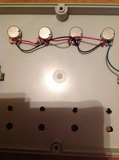
Figure 5-40. Wiring the voltage and ground pins of the potentiometers
Choosing the Right Power Supply and Getting Access to the Power Pins
You might want to use only one power supply. If your keyboard is powered by the USB cable, then you’re good to go, but in case it needs an external power supply, you’ll have to use two, one for the keyboard, and one for the Raspberry Pi. It is very likely that your keyboard operates at 9V, or maybe 12V. You can use a power supply at this voltage with enough Ambers for both the keyboard and the Pi (1 Amber is more than enough for the Pi), and use a voltage regulator to drop down the voltage for the Pi. If you open your keyboard case, you’ll get access to its power jack. You can solder wires on the bottom side of its circuit board and connect it this way to the voltage regulator, which will power the Pi. Consult your local electronics store as to which voltage regulator is best for your setup, and which capacitors you’ll need to make it work.
Accessing the MIDI Pins
In a similar way you can access the MIDI or USB cable pins. When enclosing a device in a box, usually we don’t want to have cables floating around, so we solder everything inside the box. Since the USB or MIDI connectors will be facing the outer part of the enclosure, we have to access them from their connections on the back side of their circuit boards. Figure 5-41 demonstrates accessing the pins of the MIDI connector of a keyboard. All connectors, (USB, power supply) can be accessed this way. The proper way is to remove the connector you want to have access to, and in its pins holes, connect your wires. Removing circuit components can be quite difficult. Still, you are encouraged to try it. You’ll need a solder pump and perhaps some solder wick to remove the solder from a circuit board, and then remove the component. Sometimes you might need to be a bit violent, as the solder will probably not be totally removed.

Figure 5-41. Accessing the MIDI pins of a keyboard from inside the enclosure
Whichever way you choose to make your connections, make sure you connect the correct pins, as making a mistake in the circuit can lead to damage. A multimeter can become a very good friend, since you can use its continuity to determine connections in a circuit.
Bringing the Power Input and Audio Output out of the Enclosure
Generally, it would be best if you visit your local electronics store or an online store to see what’s available for your project. The powering cable for the Pi can be an issue, for example. It might be a good idea to get a power jack to a micro USB or a USB type B–to–micro USB to power up the Pi. A roll-up USB cable is also a something to consider, as it keeps things tidy inside limited enclosure spaces. Also, the way you have access to the audio jack in the Pi is an important aspect of your project, which you should bear in mind. Figure 5-42 shows a suggestion of how you can get the Pi power input and audio output out of the enclosure.
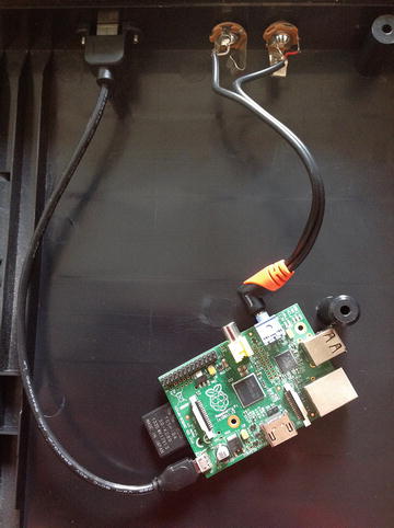
Figure 5-42. Getting the power input and audio output of the Pi outside the enclosure
Conclusion
We have now finished our first finalized project. Even if you used your computer with a USB keyboard, and you didn’t deal with enclosing your project at all, you still went through the software process, which is a fundamental process for digital electronics. If you went all the way through the enclosure process, you have been introduced to some serious project building, which enables you to realize independent, very flexible, and powerful projects. We’ll be using the Pi in other projects in this book, but the process will be very similar (if not identical) to the one we went through in this chapter.