Chapter 5: Evidence Acquisition and Preservation with dc3dd and Guymager
In the previous chapter, we learned that documentation and proper procedures are key in any investigation. These ensure the integrity of the investigation by providing proof of data authenticity and preservation of the original evidence and documentation, which can be used to achieve the same exact results if the usage of tools and methods are repeated.
In this chapter, we will demonstrate forensically sound techniques for the acquisition of data using bitstream copies, including creating data hashes, in keeping with best practices.
In this chapter, we will cover the following topics:
- Device identification in Linux
- Creating MD5 and SHA hashes
- Using dc3dd for data acquisition
- Erasing drives with dc3dd
- Using DD for data acquisition
- Using the Guymager GUI for data acquisition
The first tool we will use for acquisition is called Department of Defense Cyber Crime Center Data Dump (dc3dd). dc3dd is a patch of the very popular Data Dump (DD) tool used for forensic acquisition and hashing.
Drive and partition recognition in Linux
Users new to Kali Linux or any Linux variations may find that the drive, partition recognition, and naming in Kali Linux are different from that of Windows devices.
A typical device in Linux can be addressed or recognized as /dev/sda, whereas drives in Windows are usually recognized as Disk 0, Disk 1, and so on:
- /dev: Refers to the path of all devices and drives, which can be read from or written to, recognized by Linux
- /sda: Refers to the Small Computer System Interface (SCSI), SATA, and USB devices
The sd stands for SCSI Mass-Storage Driver, with the letter after it representing the drive number:
- sda: Drive 0, or the first drive recognized
- sdb: The second drive
While Windows recognizes partitions as primary, logical, and extended, Linux partitions are recognized as numbers after the drive letter:
- sda1: Partition 1 on the first disk (sda)
- sda2: Partition 2 on the first disk
- sdb1: Partition 1 on the second disk (sdb)
- sdb2: Partition 2 on the second disk
Device identification using the fdisk command
For the exercises in this chapter, I'll be using an old 2 GB flash drive for the acquisition process using dc3dd. At this point, we should consider attaching our media to a write blocker before examining it. It's also important to remember to continue using your write blocker when acquiring and creating forensic images of evidence and drives, in order to not write data to the drives or modify the original evidence files.
To list your devices and ensure that you are aware of them before performing any acquisition operations, the fdisk -l command should be run before any other. The sudo fdisk -l command may have to be used if the previous one does not work. The sudo command allows the user to run the command as root, which is similar to the Run as Administrator feature in Windows.
The fdisk-1 command has been executed in the following screenshot. Then, the 2 GB flash drive is attached. There is one hard disk listed as sda. The primary partition is listed as sda1, with the Extended and Linux swap partitions listed as sda2 and sda5, respectively:
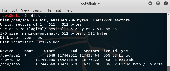
Figure 5.1 – Using the fdisk command to identify devices and partitions in Kali
After attaching the 2 GB flash drive for acquisition, the fdisk -l command was run yet again and can be seen in the following screenshot with these details:
- Disk: sdb
- Size: 1.9 GB
- Sector size: 512 bytes
- Filesystem: FAT32

Figure 5.2 – Full output of the fdisk command in Kali Linux
As seen in the preceding screenshots (and also explained earlier in this chapter), Kali Linux recognizes two devices:
Now that we've distinguished and become certain of which drive is to be imaged (sdb), we can begin the forensic imaging using dc3dd.
Important note
Although I have used an older 2 GB flash drive to demonstrate the usage of dc3dd, you can use any drive (portable or otherwise) to practice using the tools in this chapter. Be sure to use the fdisk -l command to identify your drives and partitions.
Maintaining evidence integrity
In order to provide proof that the evidence was not tampered with, a hash of the evidence should be provided before and during, or after, an acquisition.
In Kali Linux, we can use the md5sum command, followed by the path of the device, to create an MD5 hash of the evidence/input file – for example, md5sum /dev/sdx.
You may also try the command with superuser privileges by typing in sudo md5sum /dev/sdx.
For this example, the 2 GB flash drive that I'll be using (named test_usb) is recognized as sdb and the command I will be using is shown in the following screenshot:
Figure 5.3 – Creating an MD5 hash using md5sum
In the previous example, the output of the md5sum command of the 2 GB flash drive is displayed as 9f038....1c7d3 /dev/sdb. When performing the acquisition or forensic imaging of the drive using dc3dd, we should also have that exact result when hashing the created image file output to ensure that both the original evidence and the copy are exactly the same, thereby maintaining the integrity of the evidence.
I've also created an SHA-1 hash (which will be used for comparative purposes) using the following syntax:
Figure 5.4 – Creating an SHA1 hash using sha1sum
Now that we can identify our devices and create MD5 and SHA-1 hashes in Kali Linux, let's move on to using dc3dd in the next section.
Using dc3dd in Kali Linux
Before we get started using dc3dd, I need to again draw your attention to one of the features of DD: being able to wipe data, partitions, and drives. Hence, you may find that DD is sometimes also fondly referred to as the Data Destroyer. Be sure to always first identify your devices, partitions, input and output files, and parameters when using DD and dc3dd.
These are the features of DD:
- Bitstream (raw) disk acquisition and cloning
- Copying disk partitions
- Copying folders and files
- Hard disk drive error checking
- Forensic wiping of all data on hard disk drives
dc3dd was developed by the Department of Defense Cyber Crime Center and is updated whenever DD updates. dc3dd offers the best of DD with more features, including the following:
- On-the-fly hashing using more algorithm choices (MD5, SHA-1, SHA-256, and SHA-512)
- Hash verification
- A meter to monitor progress and acquisition time
- Writing of errors to a file
- Splitting of output files (mix split and unsplit outputs)
- Verification of files
- Wiping of output files (pattern wiping)
Important note
Although we'll only be looking at DD and dc3dd there is also another tool called dcfldd, which can be installed on Linux-based systems.
dc3dd is a patch of DD and is regularly updated whenever there are updates to DD. dc3dd offers more features than DD, which is why we'll be using it.
Unlike previous versions of Kali Linux, dc3dd must now be installed manually in Kali Linux 2019.3. First, we'll update our version of Kali Linux by using the apt-get update command:
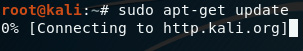
Figure 5.5 – Updating Kali Linux
Once Kali Linux updates, you can manually install dc3dd by typing in the sudo apt-get install dc3dd command. It is recommended to install dc3dd on your flash drive or SD card before performing any live acquisitions and not do so at the time of acquisition, which may tamper with the investigation:

Figure 5.6 – Installing dc3dd in Kali Linux
dc3dd is a CLI tool and can be easily run in Kali Linux by first opening a Terminal and typing in dc3dd. To start with, I recommend using the dc3dd --help command, which lists the available parameters used with dc3dd:
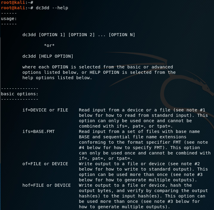
Figure 5.7 – Viewing the dc3dd help options
Important note
When copying an image to a drive, the destination drive size should be of equal size or larger than the image file.
As seen in the preceding screenshot, when using the dc3dd --help command, the typical usage looks as follows:
dc3dd [option 1] [option 2] ... [option n]
In our previous example, I've used the following options:
Figure 5.8 – Using dc3dd to create an MD5 hash and bit-stream copy of SDB
The code terms used here are:
- if: Specifies the input file, which is the device we will be imaging.
- hash: Specifies the type of hash algorithm we will be using for integrity verification. In this case, I have used the older MD5 hash.
- log: Specifies the name of the log file that logs the details of the device and the acquisition, including errors.
- of: Specifies the output filename of the forensic image created by dc3dd. Although a .dd image file type was specified in this example, other formats are also recognized by dc3dd, including .img, as seen in a later example.
The device size (in sector and bytes) should be noted and later compared to the output results for device field.
The last line also displays the progress and status of the acquisition process, showing the amount of data copied, the elapsed time in seconds, and the speed of the imaging process in Mbps:
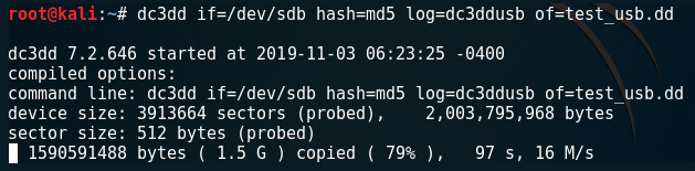
Figure 5.9 – Output of the dc3dd command
Important note
The larger the drive or file to be acquired, the lengthier the time taken to do so. Might I suggest you get yourself a cup of coffee or other refreshing beverage, or even have a look at some other wonderful titles available from Packt Publishing at https://www.packtpub.com/.
Once the acquisition process has been completed, the input and output results are displayed as follows:
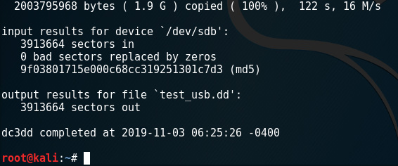
Figure 5.10 – Output of the dc3dd command displaying the MD5 hash
Analyzing the results, we can see that the same amount of sectors (3913664) have been imaged, with no bad sectors being replaced by zeros. We can also see that the exact MD5 hash was created for the image, assuring us that an exact copy was created without modification.
In the Terminal, we can also use the ls command to list the directory contents to ensure the dc3dd output file (test_usb.dd) and log (dc3ddusb) have been created:
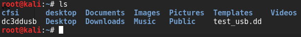
Figure 5.11 – Output of the ls command
To access our forensic image and log file, we can go to our /home directory by clicking on places (top-left corner) and then Home.
Within my Home folder, the first file, 2GBdcedd.dd, is the output image created by dc3dd using the of=test_usb.dd command. The last file, dc3ddusb, is the log file, created when we used the log=dc3ddusb command:
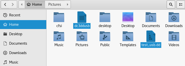
Figure 5.12 – Screenshot of the output file location
It's important to keep this log file to have a record of the acquisition process and its results, which are displayed on-screen upon completion:
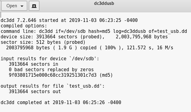
Figure 5.13 – Screenshot of the log file generated by dc3dd
In future chapters, we will be analyzing acquired forensic images using various tools. However, the image can also be copied or directly cloned to another device if the investigator so wishes.
As an example, we could clone the forensic image acquired previously (test_usb.dd) onto a new drive recognized as sdc. The command used to perform this task is as follows:
dc3dd if=test_usb.dd of=/dev/sdc log=drivecopy.log
In keeping with proper and formal case management, the names of the image file and log file should be unique to the investigator and the investigation for easy reference, as you may find yourself with multiple images and log files later on. The location of the images should also be stored on forensically sound or sanitized drives and labeled accordingly.
File-splitting using dc3dd
Depending on the size of the evidence, manageability and portability can become an issue. dc3dd has the ability to split forensically acquired images into multiple parts.
This is accomplished using the ofsz and ofs options:
- ofsz specifies the size of each output file part.
- ofs specifies the output files with numerical file extensions, typically .000, .001, .002, and so on.
Tip
Always ensure that you have specified enough zeros for the file extension. Logically, .000 allows for more parts than .00.
For this example, I've used the same 2 GB flash drive as before. However, for demonstrative purposes, you'll notice two changes.
Instead of using the MD5 hash, I've specified that SHA-1 be used and the output file type will be .img instead of the previously used .dd.
In this instance, the imaged 2 GB flash size will instead be split into multiple parts (four in total) of 500 MB each using ofsz=500M with the parts named as 2GBdc3dd2.img.ooo, 2GBdc3dd2.img.oo1, 2GBdc3dd2.img.oo2, and 2GBdc3dd2.img.oo3.
The command used to achieve this is as follows:
dc3dd if=/dev/sdb hash=sha1 log=dd_split_usb ofsz=500M ofs=split_test_usb.img.ooo
In the following screenshot, we can see the command as well as the output and status of the process:

Figure 5.14 – The command used to split the acquired file size
Once completed, the input results for the device show the SHA-1 hash output and also display the first part of the split image files:
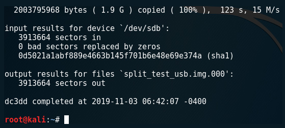
Figure 5.15 – The output of the sha1sum option using dc3dd
Using the ls command once more, we can see that the extensions of each of the four split output files are all in numerical format, from .000 to .003:

Figure 5.16 – The output of the ls command showing created acquisition images
All split parts of the image file can be found in the Home folder along with the log file:

Figure 5.17 – Screenshot of the folder location containing the created acquisition images
Now that we have successfully created bitstream copies of the evidence, let's look at verifying the integrity of the forensic acquisitions using hash verification.
Hash verification
Double-clicking on the .info file in the Image directory location allows us to inspect a variety of details about the acquisition process from start to completion, including the hashed outputs.
This .info file contains much more data than the log file produced by dc3dd, including the case management details:

Figure 5.18 – Screenshot of the log file displaying hash values
Let's have a closer look at the hash details within the .info file.
We can see that the MD5 and SHA-1 hashes have been created and verified and, as stated in the last line of the following screenshot, Image verification OK. The image contains exactly the data that was written:

Figure 5.19 – Screenshot of log file displaying hash verification
If we compare these hashes with the ones created using dc3dd we would have the exact same MD5 and SHA-1 outputs, proving that these images are exact forensic copies of the original evidence.
Compare the hashes in the following screenshots, created by dc3dd, with the ones in the previous screenshots, created by Guymager:
- dc3dd MD5 hash:
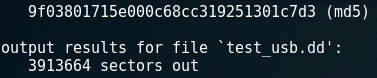
Figure 5.20 – MD5 calculation output
- dc3dd SHA-1 hash:
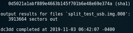
Figure 5.21 – SHA-1 calculation output
If we look at the preceding hashes and compare them with the ones created by Guymager in the .info file, we can see that the SHA-1 hash contains more characters than the MD5 hash, as the MD5 (although faster) has a 128-bit output whereas the SHA-1 has a 160-bit output. I'd highly recommend using SHA-1 or SHA256 instead of MD5 as MD5 is outdated and no longer used as it was proven to be vulnerable to hash collision attacks, where different sets of hashed data can produce the same output, rendering it invalid. More on MD5 collisions can be found in this document, written by the researchers responsible for discovering the vulnerability, at http://merlot.usc.edu/csac-f06/papers/Wang05a.pdf.
Verifying hashes of split image files
To verify the hash of the split files, the following command can be used:
cat split_test_usb.img.* | sha1sum
In the following screenshot, we can see that a lengthy SHA-1 hash was created using the preceding command:

Figure 5.22 – SHA1sum split-file verification output
This also matches the sha1sum output of the 2 GB flash drive itself, displayed by using the following command:
sha1sum /dev/sdb
Using this command creates the following output:

Figure 5.23 – SHA1sum output
With our verification processes now complete, we'll look at using dc3dd to forensically wipe drives.
Erasing a drive using dc3dd
We've seen the power of dc3dd as a very impressive forensic acquisition tool, but I'd also like to go one step further and introduce you to its capabilities as a data wiping tool.
dc3dd can wipe data and erase drives by overwriting data in three ways:
- Overwriting and filling the data and drives with zeroes. The command used is dc3dd wipe=/dev/sdb:
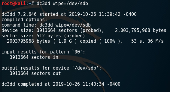
Figure 5.24 – dc3dd wipe command output
- Overwriting and filling the data and drives using a hexadecimal pattern using the pat option. The command used is dc3dd wipe=/dev/sdb pat=000111:
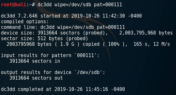
Figure 5.25 – Using dc3dd to wipe a drive using a hexadecimal pattern
- Overwriting and filling the data and drives using a text pattern using the tpat option. The command used is dc3dd wipe=/dev/sdb tpat=cfsi:

Figure 5.26 – Using dc3dd to wipe a drive using a text pattern
All three of the preceding methods efficiently erase drives. Let's also look at using the DD command, which is pre-installed in Kali Linux, to make forensic bitstream copies of evidence.
Image acquisition using DD
Should you also wish to use the DD tool, the commands and usage are very much the same.
You may want to first ensure that you can access the DD tool by running dd –-help. If the dd command cannot be found, update Kali Linux by running the apt-get update command and then running the dd –-help command again:

Figure 5.27 – Output of the dd help command
Attach the storage you wish to acquire. For this example, I'll be using an older 2 GB Sony Pro Duo card that I'd like to image and analyze.
Run the fdisk –l command in the Terminal to view the device details. In the following screenshot, we can see that the device is recognized as /dev/sdb and is 1.89 GB with a default sector size of 512 bytes:

Figure 5.28 – Output of the fdisk -l command
I'll also manually create hashes to verify the integrity of the created images by comparing the hashes of the images with these.
To create the MD5 hash, run the md5sum /dev/sbd command:

Figure 5.29 – Output of the md5sum command
To create the SHA-1 hash, run the sha1sum /dev/sbd command:

Figure 5.30 – Output of the sha1sum command
To perform image acquisition, I've used this command:
dd if=/dev/sdb of=sdb_image.img bs=65536 conv=noerror,sync
The following command output shows that the input and output records match, along with the speed of the acquisition at 54.6 MB/s:

Figure 5.31 – Output showing a record in and record out comparison
Let's do a breakdown of the individual options in the preceding command:
- if: Input file (sdb device).
- of: Output file (name of the forensic image).
- bs: Block size (default size is 512).
- conv=noerror, sync: Continue the imaging even if there are errors (noerror) and if there are errors, null fill the blocks (sync).
In the preceding command, the output file extension, .dd, was specified. However, you can use another format, such as .iso, but specifying such in the output file (of) option:

Figure 5.32 – Output showing a record in and record out comparison using the .iso extension
We can view the created files in two ways. The first option is to click on Places and then click on Home. We can see two items listed as the produo_image.dd and produo_image.iso files that were created by DD:
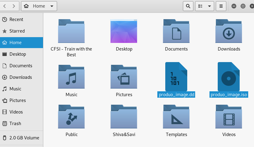
Figure 5.33 – Screenshot of the .iso file location
The second option is to simply use the ls command, where we can also see the two images:
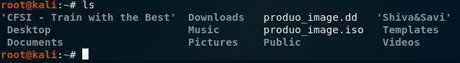
Figure 5.34 – Output of the ls command
Now that we've used dc3dd to create forensic images, used md5sum and sha1sum to verify our images, and used DD to wipe drives, let's now have a look at Guymager, which also performs image acquisition via a simple GUI.
Image acquisition using Guymager
Guymager is another standalone acquisition tool that can be used for creating forensic images and performing disk cloning. Developed by Guy Voncken, Guymager is completely open source, has many of the same features of dc3dd, and is also only available for Linux-based hosts. While some investigators may prefer CLI tools, Guymager is a GUI tool and is for beginners, so it may be preferable.
For this acquisition, I'll use the very same 2-GB flash drive used in the dc3dd examples, at the end of which we can compare results.
As previously done in the dc3dd acquisition, we should first ensure that we are familiar with the devices attached to our machine, using the fdisk -l or sudo fdisk -l command.
Running Guymager
Guymager can be started by using the menu in Kali Linux. Click on Applications on the side menu, then click on Forensics and scroll down to Guymager:
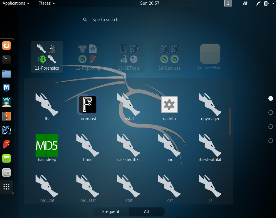
Figure 5.35 – Screenshot to the Forensic Tool menu in Kali Linux
Guymager can also be started using the Terminal by typing in guymager. You may also try the sudo guymager command. Once started, the default locations of the log file and configuration (cfg) files can be changed if required:
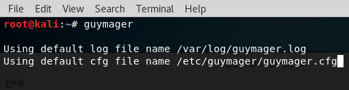
Figure 5.36 – Starting Guymager in Kali using the CLI
The Guymager application runs and then displays the existing drives recognized in Kali Linux. As in the following screenshot, the details of the 2 GB flash drive being used are shown, including the following:
- Linux device: Recognized as /dev/sdb
- Model: USB_Flash_Memory
- State: Shown as Idle as the image acquisition has not yet begun
- Size: 2.0GB

Figure 5.37 – Guymager interface displaying detected drives
Should your device not be listed in Guymager, or should you need to add an additional device, click the Rescan button at the top-left corner of the application.
Acquiring evidence with Guymager
To begin the acquisition process, right-click on the evidence drive (/dev/sdb in this example) and select Acquire image. Note that the Clone device option is also available should you wish to clone the evidence drive to another. Again, as previously mentioned, when cloning a device, the capacity of the destination device must be equal to or exceed that of the source (original) evidence drive:
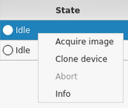
Figure 5.38 – Image acquisition shortcuts
Before the actual acquisition process starts, the investigator is prompted to enter details about themselves and the evidence under the following three sections:
File format:
- File extensions: .dd, .xxx, and .Exx.
- Split size: Allows the investigator to choose the size of multiple image parts.
- Case management information: Case number, evidence number, examiner name, description, and notes:
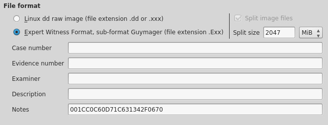
Figure 5.39 – Guymager image acquisition fields
Destination:
- Image directory: The location of the created image file and log (info file)
- Image filename: The name of the image file
- Info filename: The name of the log file containing acquisition details:

Figure 5.40 – Guymager image destination fields
- Hash calculation / verification: Multiple hashing algorithms can be selected and calculated, allowing the investigator to choose from MD5, SHA-1, and SHA256.
- Re-read source after acquisition for verification: This verifies the source.
- Verify image after acquisition: This verifies that the image has been successfully created and does not contain any errors that may have occurred during acquisition.
Important note
Guymager also adds the convenience of having a Duplicate image... button to create duplicate copies without having to repeat the data entry process.
For new users, you may want to specify the directory where the image file will be saved. In the destination section, click on the Image directory button and choose your location. You should choose a drive or directory that is unique to the case as the location for both the image and the log/info file:

Figure 5.41 – Guymager image destination directory selection screen
The following screenshot shows the data that I've used for the Guymager acquisition, having chosen the desktop as the Image directory and MD5 and SHA-1 hashing algorithms:
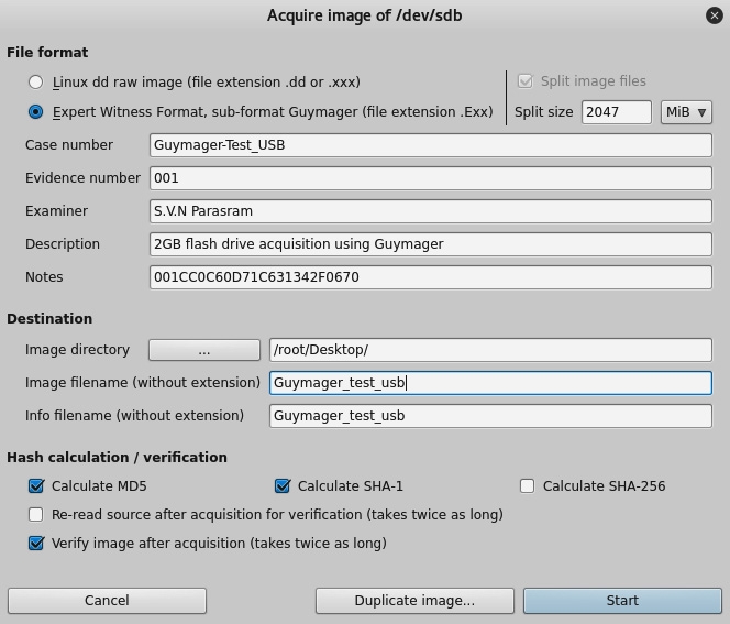
Figure 5.42 – Snippet of the completed Guymager image acquisition fields
Once the Start button is clicked, you will notice that the State changes from Idle to Running. The Progress field also now displays a progress bar:
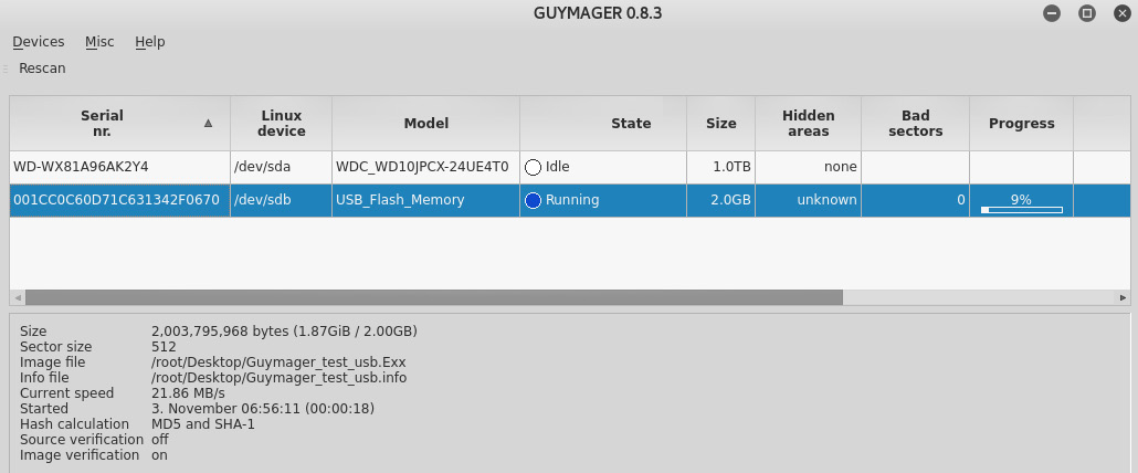
Figure 5.43 – Snippet of the acquisition process and status in Guymager
Taking a closer look at the details in the lower-left corner of the screen, we see the size, image, info file paths, names and extensions, current speed, and chosen hash calculations. We also see that Image verification is turned on:

Figure 5.44 – Snippet of the image acquisition details
Once the acquisition process is completed, the color of the State button changes from blue to green, indicating that the acquisition process is finished. It also displays Finished - Verified & ok if verification options were selected in the Hash verification / calculation area. The progress bar also displays 100%:
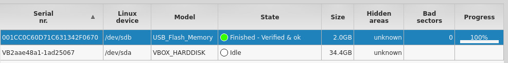
Figure 5.45 – Snippet of the acquisition process and status in Guymager
Our output file and info file can be found on the desktop as this was specified in the Acquire images section earlier. If you have selected a different directory, change to the new directory, using the cd command, in a new Terminal. In the following screenshot, I've changed to the Desktop directory using the cd Desktop command and then listed the contents using the ls command:
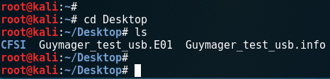
Figure 5.46 – Viewing the acquired images using the ls command
We can also browse the desktop, or even the desktop folder, to open the info file, which presents us with information about the acquisition details:
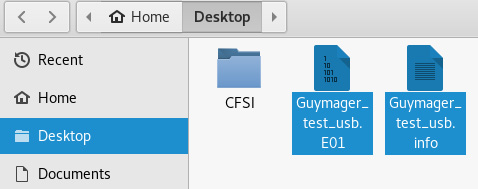
Figure 5.47 – Snippet of the location of the image file
Using Guymager may be much simpler for those that are unfamiliar with DD or dc3dd, also because Guymager comes pre-installed on Kali Linux. Let's now move on to some tools that can be used for live memory acquisition.
Windows memory acquisition
There are several tools for Windows systems that you may wish to take advantage of to be able to capture the memory and paging file on a Windows device. The forensic images can then be opened on your Kali Linux machine for analysis with Volatility, as we'll delve into in a later chapter.
FTK Imager
Forensic Toolkit (FTK) Imager from AccessData is a free tool for the live acquisition of memory, the paging file, and drive images. To download FTK Imager, visit their website at https://accessdata.com/product-download/ftk-imager-version-4-2-1 and click on the Download Now button, which then carries you to their registration page.
Once all the fields are completed, a download link will be sent to the email address which you specified. The file size is approximately 53 MB and, at the time of writing, I've downloaded version 4.2.1 but any version between 4.0 and 4.2.1 will do for this exercise.
Important note
Remember that this tool is to be installed on a Windows machine and not on Kali Linux.
Once downloaded and installed, open the program:
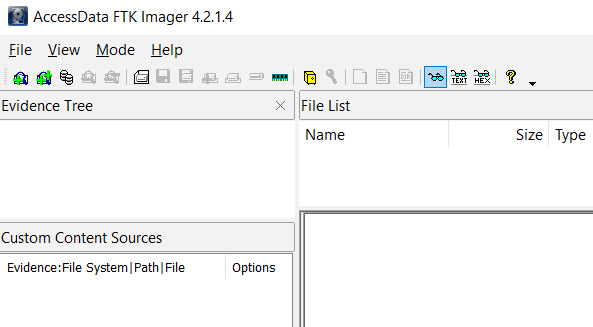
Figure 5.48 – FTK imager interface
To view the options for imaging and acquisition, click on File:

Figure 5.49 – Snippet of the File menu in FTK imager
Within the File menu, we are presented with all the options needed. The Create Disk Image… option allows you to perform a forensic acquisition of physical and logical drives, contents of a folder, and CDs and DVDs. Click on the Create Disk Image… option:

Figure 5.50 – Source evidence selection screen
Click on Next > to continue. I've selected a 32 GB Kingston Physical drive to acquire. You may select any drive of your choice. Once selected, click on Finish:
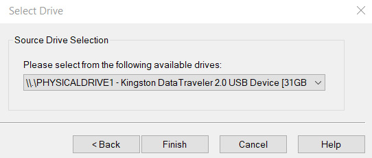
Figure 5.51 – Source drive selection screen
Next, we'll need to choose a destination to save the image file to. Click on Add and choose the image type (Raw (dd), SMART, E01, or AFF). E01 is the Expert Witness Compression Format and is one of the more common formats as it is widely recognized by many tools, including EnCase, FTK, and Autopsy. More on the file format types can be found at https://www.loc.gov/preservation/digital/formats/fdd/generic_fdd.shtml.
Click on Next > to proceed:

Figure 5.52 – Destination image type selection screen
Complete the forms with the Evidence Item Information fields and click on Next >:
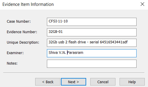
Figure 5.53 – Evidence item information details
Lastly, click on Browse to select the image destination folder and type in a filename with an extension:
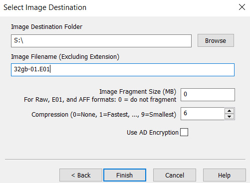
Figure 5.54 – Image destination folder and filename details
I've specified the Image Fragment Size to be a value of 0. This tells the software to not fragment or split the image file. Click on Finish and then click on Start to begin the process. Be sure to select the option to calculate the MD5 or SHA hash upon creation when prompted:

Figure 5.55 – Image creation status screen
The created disk image can now be analyzed using tools of your choice.
RAM acquisition with FTK Imager
We can also perform live acquisition with FTK Imager whereby we acquire the RAM and paging file.
Click on File and Capture Memory…:

Figure 5.56 – RAM acquisition details
Next, select the destination path and specify a filename for the memory dump (.mem) file. To include the page file, select the Include pagefile checkbox.
Click on Capture Memory to begin the acquisition process:
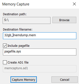
Figure 5.57 – Memory capture details screen
The status bar indicates when the process is completed. This is usually not a lengthy process compared to the static dive acquisition process:

Figure 5.58 – Memory capture progress screen
Let's look at another free tool for memory acquisition on Windows devices called Belkasoft RAM Capturer.
Belkasoft RAM Capturer
Belkasoft also has a full suite of tools available for forensic acquisition and analysis along with the free RAM capturer tool, which can be downloaded from https://belkasoft.com/ram-capturer. Click on the DOWNLOAD NOW button and enter your email address, then click on Proceed. An email with the download link should be sent to you within an hour.
Once downloaded and extracted on your Windows machine, choose the appropriate version (x86 or x64) and launch the environment.
The GUI is as simple as it gets with Belkasoft RAM Capturer. You are prompted to specify an output folder path and from there it captures the memory and paging file after clicking on Capture!:
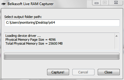
Figure 5.59 – Belkasoft Live RAM Capturer interface
The tool takes a few minutes to perform the acquisition, and from there you can hash and analyze using the tools of your choice.
Opening the output folder, I can see that the file is saved as a .mem file (20191115.mem) with the date of acquisition as the date:
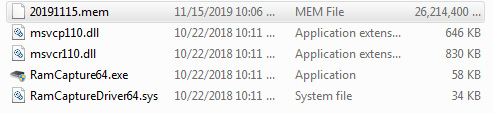
Figure 5.60 – Screenshot of the memory capture file within the Belkasoft folder
You'd have probably noticed that both FTK Imager and Belkasoft RAM Capturer are very fast and efficient tools for performing RAM and paging file acquisitions on Windows machines. The choice is yours when performing memory acquisitions for later analysis which we'll look at in a later chapter where we'll use Volatility to find artifacts stored in memory and even perhaps find traces of malware.
Summary
In this chapter, we've looked at two tools readily available in Kali Linux for the acquisition of digital evidence. It's very important to be able to tell your devices apart so you can accurately acquire a forensic and exact copy or image of the evidence file using the fdisk - l command. For forensic analysis, bitstream copies of the evidence are needed as these provide an exact copy of the evidence, bit by bit, which is why we used dc3dd and Guymager.
Firstly, we used dc3dd, the enhancement of the data dump tool, and through the Terminal performed quite a few tasks, including device imaging, hashing, splitting of files, and file verification. Our second tool, Guymager, has built-in case-management abilities and also has many functional similarities to dc3dd, but it comes as a GUI tool and may be easier to use.
Both tools deliver accurate and forensically sound results. For those who may not constantly work with DD and dc3dd, Guymager may be the easier tool to use seeing that all acquisition options, including cloning, are readily available through the GUI.
We also looked at FTK Imager and Belkasoft Ram Capturer. FTK Imager runs on Windows and is capable of acquiring RAM and disk images, whereas Belkasoft RAM Capturer (also for Windows) performs only RAM acquisition.
Next, we'll move on to file recovery and data carving using three very powerful tools. Exciting stuff!