
STEP-BY-STEP CARS
CREATING THE LAMBORGHINI AVENTADOR
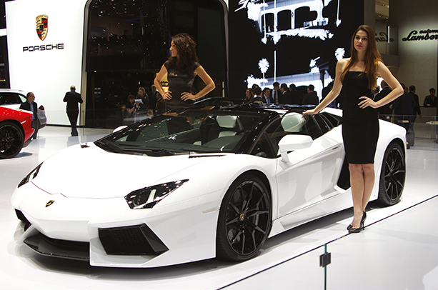
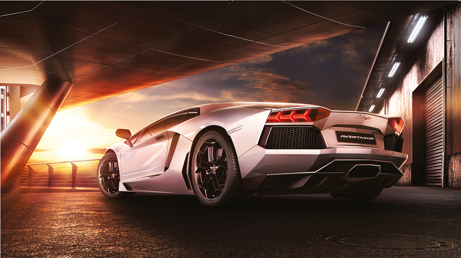
Michael Hirsch reveals how he modelled, textured and lit the ultimate, luxury sports-car from Italy in 3ds Max, using the Madcar plug-in.
CONCEPT BACKGROUND
There was a fantastic, expensive car, built in Italy, called the Lamborghini Aventador that featured a V12 engine, capable of 0–100 km/h in 2,9 sec and with a top speed of 350 km/h. With futuristic styling for the carbon fibre body, I was really impressed by the car and decided my next CGI project in Maya would be to create one.
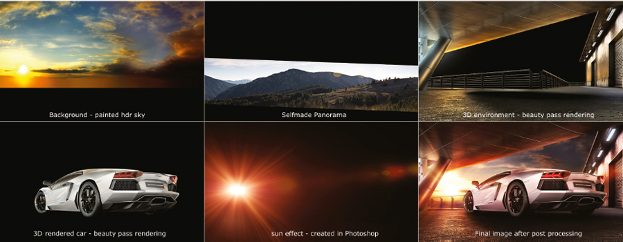
To start with, I had the idea of an old factory building in combination with a new piece of architecture which should symbolize the temporal change, and somewhere in the middle would be the Aventador.
It was time to think about the car paint colour. I knew it should be a bright colour, maybe metallic white. I love white cars and in my opinion, a white paintwork fits perfectly into a sunset situation. I used this creative decision as a starting point for my new project which was to be called, “Dream Factory”.
STEP 1
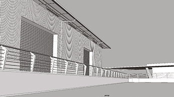
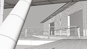
MODELLING THE FACTORY
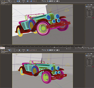
First of all, I went on the web to search for some photo reference materials. By looking at the actual car from various angles you get a good idea of how it should look. The alternative is to get hold of blueprints of a vehicle, if you want to make a perfectly accurate version. For modelling the assets, I used the poly modelling technique. I just added details at the points of interest. The first stage was to build the factory itself.
STEP 2
ADDING DETAILS
The key point was to have a roof overhead, but that the side would be wide open to let the light in. I added basic circular tubes as supports and created the fence and doors to the factory area.
STEP 3
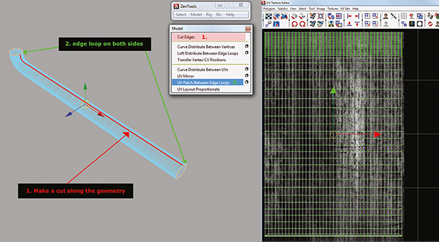
UNWRAPPING THE UVS
For the UV setup I used standard mapping techniques like planar, cylindrical and automatic mapping. Furthermore I used a very nice tool called “ZenTools”. This tool makes unwrapping of complex geometries very easy. You just have to select the first and the last edge of an object and the tool does the rest – very clean and fast.
| PROJECT | DREAM FACTORY – LAMBORGHINI AVENTADOR |
| SOFTWARE USED | AUTODESK MAYA, V-RAY FOR MAYA, ADOBE PHOTOSHOP |
| RENDERING TIME | APPROXIMATELY 3 HOURS FOR THE CAR PASSES AND 8 HOURS FOR THE ENVIRONMENT |
| ARTIST | MICHAEL HIRSCH |
| COUNTRY | GERMANY (MUNICH) |
STEP 4
CREATING TEXTURES
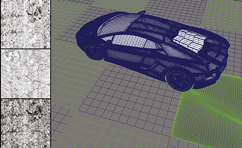
For texturing the buildings and the floor, I used Photoshop and my DSLR camera. I shot all images in RAW format to achieve more flexibility and higher quality textures. For the floor I created three different high resolution displacement maps. For a better result and more flexibility, I split the ground plane in smaller pieces by the same proportions.
STEP 5
ANGLE HUNTING
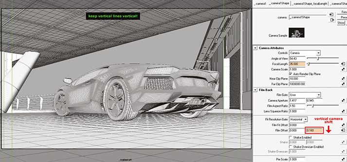
Almost every time, when I start modelling an environment, I know pretty well how the scene should look before I am finished. It’s exciting for me in a still project to find a nice camera perspective. In this image, there were a lot of things I had to pay attention to. The first was the car’s position. The second was the final alignment of the buildings. The third was to find a good looking camera angle which is equally suited for architectural photography and also car photography. For the maximum amount of realism in architectural photography it’s best to keep vertical lines actually vertical. In this case the camera has to be at a 90 degree angle, horizontal to the floor. To get the result I wanted I took advantage of a technique called “lens shift” so that the car was standing in the position I wanted with the vertical lines of the architecture still in their vertical position.
STEP 6
SHADING AND LIGHTING
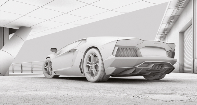
After modelling the scene and creating the UVs and the textures, it was time for a render preview in an Ambient Occlusion look, to prove whether all the geometrical parts and the displacement textures were working.
STEP 7
LIGHTING POSITIONS
For lighting the scene I used three different types of lighting. You can see in this Screenshot all the various sources, designed to shine onto the car to make sure it was bright, even with the bright sunlight outside.

STEP 8
NATURAL LIGHT
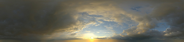
For the natural lighting I used a V-Ray Domelight with an integrated sunset HDR. Furthermore, some area lights for the building were used to simulate artificial light sources. The car itself interacts with all the light sources in the scene. For accentuating the car body form, I used specular lights in the form of area lights. The wheels got a brightener in the form of two spot lights. On the opposite side I used a rim light for the trunk to get the feeling of more depth.
STEP 9
PAINT SHADING
For the car paint I used a V-Ray blend material to control diffuse colour, specular highlights and reflection values separately. In realistic environments, the car paint consists of more paint layers. For example, the base colour layer, metallic effect layer and a clear coat layer.
STEP 10
RENDERING THE SCENE
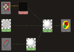
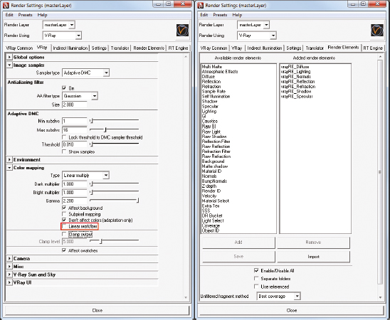
For rendering the whole scene I used V-Ray. I rendered the complete scene with render elements to get maintain flexibility in the post process later. I rendered eight different layers plus some RGB masks for the car and environment. These included diffuse lighting, normals, reflection, refraction, shadow, specular layer and Z-depth layer. For the linear workflow I used the method with a gamma correction node in all shaders and not the method over the linear workflow button in the Vray Render settings, because this button is for testing purposes only. For better handling in Photoshop I rendered the car and the environment separately.
STEP 11
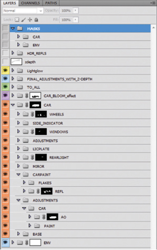
COMPOSITING AND ADDING THE FINAL TOUCHES
The time had finally arrived to add the final touches in Photoshop, to bring more drama into play, with sun rays, haze effects, a little bit of photographic grain, depth-of-field and so on, but with as little manual retouching as possible.
STEP 12
REFLECTION LAYERS
I try to squeeze as much as possible out of the 3D part so that I have as little as possible to add in Photoshop other than final colour corrections and some reflection improvements. For the reflection improvements of the car I rendered four different reflection layers – one each for the side, the trunk, the front and the top part. This is nothing different to what a professional automobile photographer does when shooting on location to get the most out of the car.
|
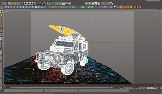
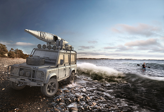
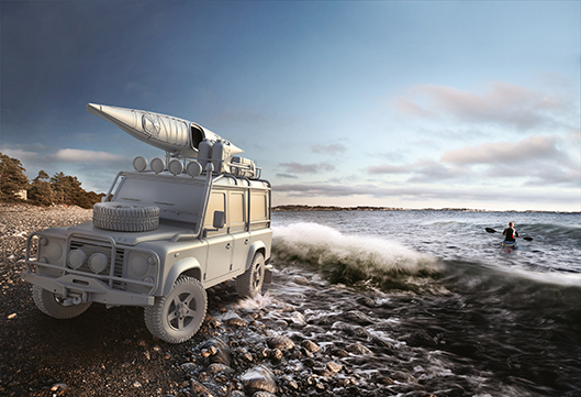
![]() Personal project together with my former colleague, car photographer Karl-Fredrik von Hausswolff. The car model was originally purchased, but we edited some topology for better rendering, modelled the kayak, some props and new alloys. We shot the backplate and an HDR image at Torö beach near Stockholm. This was later used for most of the lighting and reflections, but I also added some CG fill lights to give the front of the car some gradients. The final render was later composed and retouched together with the backplate in Photoshop, where I also added the final colours and effects.
Personal project together with my former colleague, car photographer Karl-Fredrik von Hausswolff. The car model was originally purchased, but we edited some topology for better rendering, modelled the kayak, some props and new alloys. We shot the backplate and an HDR image at Torö beach near Stockholm. This was later used for most of the lighting and reflections, but I also added some CG fill lights to give the front of the car some gradients. The final render was later composed and retouched together with the backplate in Photoshop, where I also added the final colours and effects.![]()
| PROJECT | MORNING GLORY |
| SOFTWARE USED | CINEMA 4D, MAXWELL RENDER |
| RENDERING TIME | 4–5 HOURS |
| ARTIST | FREDERIK TENNHOLT |
| COUNTRY | SWEDEN |
The topology of the oar was edited in CINEMA4D to create better surface definition for rendering.
Render without textures to see where the light worked and where it needed extra spots.

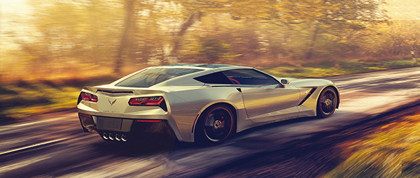
![]() The all-new 2014 Chevy Corvette Stingray. The car was modelled in 3ds Max on ! a section of road with a couple of CG trees in the background to generate and catch shows for the final image. It was then rendered using Mental Bay and Iray. The car onto the Scenery backplate was done, impression of speed. I wanted to create a beautiful image that showcased the amazing shape of this car.
The all-new 2014 Chevy Corvette Stingray. The car was modelled in 3ds Max on ! a section of road with a couple of CG trees in the background to generate and catch shows for the final image. It was then rendered using Mental Bay and Iray. The car onto the Scenery backplate was done, impression of speed. I wanted to create a beautiful image that showcased the amazing shape of this car.![]()
| PROJECT | 2014 CHEVROLET CORVETTE STINGRAY |
| SOFTWARE USED | 3DS MAX, MENTAL RAY, IRAY, PHOTOSHOP |
| RENDERING TIME | APPROXIMATELY 4 HOURS |
| ARTIST | ISAIAH TAKAHASHI |
| COUNTRY | USA |
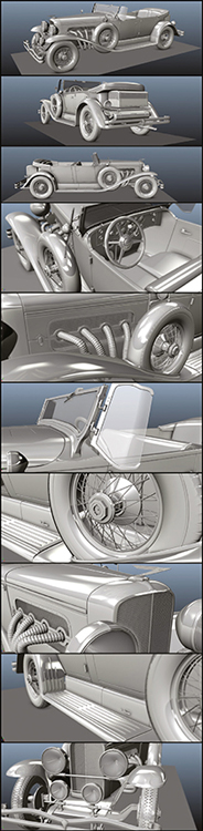
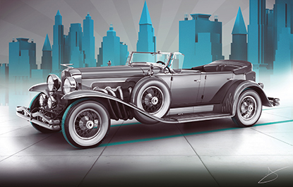
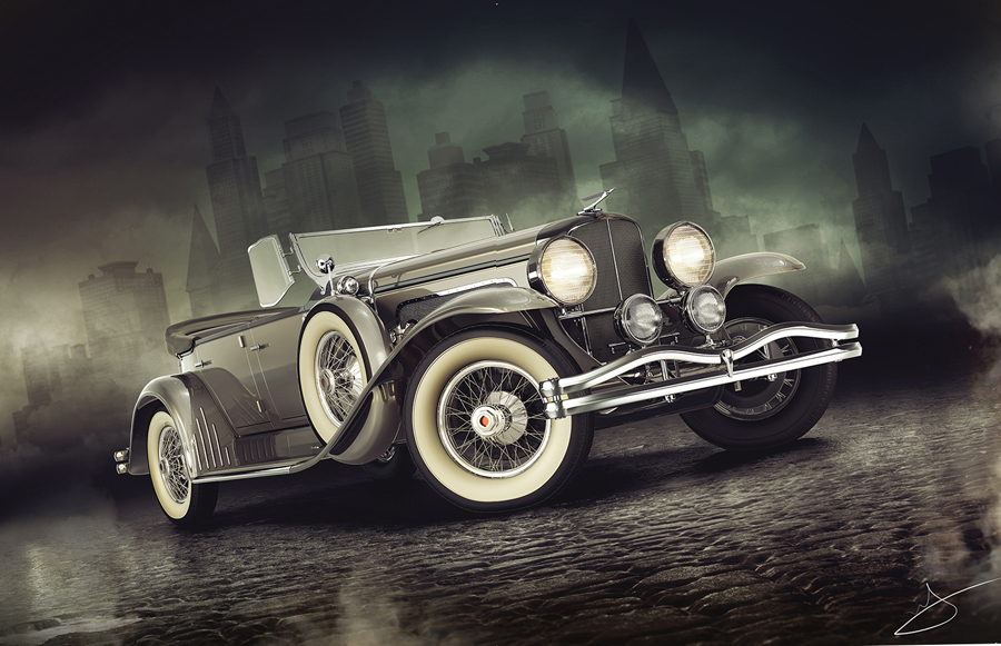
![]() The model of the Duesenberg was created and lit in Maya. The backgrounds are basic building shapes with textures to show windows and other background detail. Photoshop was used to create the atmosphere and colour styling. There was a lot of detail in the model to really show how intricate the car actually was. Rendering was done in V-Ray. It’s one of my favourite cars because of the gorgeous design and sleek, clean lines,
The model of the Duesenberg was created and lit in Maya. The backgrounds are basic building shapes with textures to show windows and other background detail. Photoshop was used to create the atmosphere and colour styling. There was a lot of detail in the model to really show how intricate the car actually was. Rendering was done in V-Ray. It’s one of my favourite cars because of the gorgeous design and sleek, clean lines,![]()
| PROJECT | 1929 DUESENBERG MODEL J DUAL COWL PHAETON |
| SOFTWARE USED | MAYA, 3DS MAX, V-RAY, PHOTOSHOP |
| RENDERING TIME | APPROX 4 HOURS |
| ARTIST | ALEXANDR NOVITSKIY |
| COUNTRY | UKRAINE |
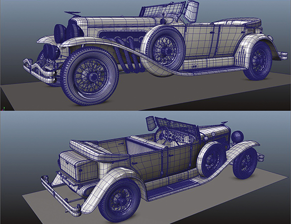
The wireframe model completed in Maya to show all the tiny details.
Adding lighting effects to bring the car to life prior to rendering.
Ready in the scene with the box-building backgrounds that would just be visible in the scene.
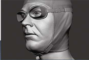
Modelling Bob Burman’s head in ZBrush to ensure as accurate a resemblance as possible.
The intricate engineering was modelled while referring to original drawing and plans of the car.
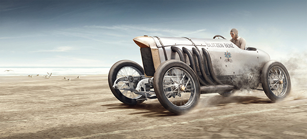
![]() In 1911, Bob Burman ripped across the immensity of Daytona Beach at a record speed of 228.1 kmph. The sound and speed of his Blitzen Benz as it carved through the sand changed man’s perception of what was possible. Now, for the first time ever and in stunning detail, Bob Burman’s reminder of what we can achieve with technology can be seen in a new light. In full CGI and astonishing 15.000px resolution, Playground have brought this extraordinary shot forward in time so that once again, it shifts our view on how quickly we’re moving towards the possible.
In 1911, Bob Burman ripped across the immensity of Daytona Beach at a record speed of 228.1 kmph. The sound and speed of his Blitzen Benz as it carved through the sand changed man’s perception of what was possible. Now, for the first time ever and in stunning detail, Bob Burman’s reminder of what we can achieve with technology can be seen in a new light. In full CGI and astonishing 15.000px resolution, Playground have brought this extraordinary shot forward in time so that once again, it shifts our view on how quickly we’re moving towards the possible.![]()
| PROJECT | BOB BURMAN’S BLITZEN BENZ |
| SOFTWARE USED | 3DS MAX, ZBRUSH, PHOTOSHOP |
| RENDERING TIME | 16 HOURS, FOR THREE SEPARATE LAYERS |
| ARTIST | PLAYGROUND PRAGUE |
| COUNTRY | CZECH REPUBLIC |
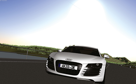
HOW TO ANIMATE AN AUDI A8
André Kutscherauer explains how to rig and animate a car inside 3ds Max, using the Madcar plug-in.
ANIMATING A CAR
The purpose of this tutorial it to show how easy and fun it is to animate a car with the Madcar plug-in within 3ds Max. You will learn how to prepare a finished modelled car for animating with Madcar, how to rig it and how to set up and fine tune Madcar. There are some essential tips on how to realise a whole car animation sequence with different camera views. Discover how to set up the whole car rig and how to fine tune the physics settings of the plug-in. Finally you simply need to plug in your game controller and start driving your car like in a video game, even with analog input! Madcar will calculate every car movement in realtime. There is a finished animation that can be viewed on www.ak3d.de.

| PROJECT | AUDI A8 |
| SOFTWARE USED | 3DS MAX, RHINOCEROS, MADCAR, IRAY |
| RENDERING TIME | ABOUT 2 HOURS |
| ARTIST | ANDRÉ KUTSCHERAUER |
| COUNTRY | GERMANY |

STEP1
MODELLING THE CAR
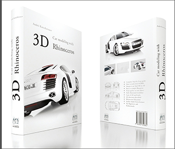
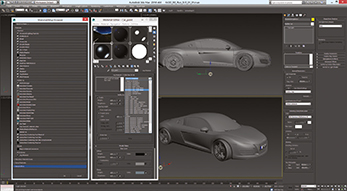
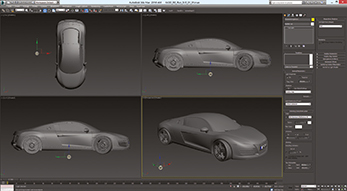
The first step is to model a car. I have written a 650-page tutorial on how to model an Audi R8 in high quality with Rhinoceros. It is available as a real book or as direct PDF download on www.ak3d.de. You will learn how to construct the whole model from scratch up to the quality as seen on these renderings and in the animation. Each working step is illustrated with a screenshot, the tool used with an icon and a description what to do. For this MadCar tutorial you can then use your own car model or one downloaded from a resource site.
STEP 2
GROUPING THE OBJECTS
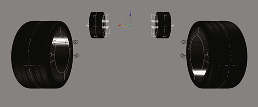
Once you have a finished 3D car model, the next step is to arrange the objects into nine groups that are relevant for animation. There are four groups for the wheels, four groups for the brake system and one group for the chassis. The four extra groups for the brake system are important, because the braking system is attached to the suspension, but of course not to the rotation of the wheels.
STEP 3
SETTING UP THE PIVOT POINTS
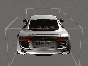
For these nine groups we have to set up the pivot points of every group precisely. The pivot points of the wheels should be exactly in the middle of each wheel as otherwise they will not rotate smoothly. The pivot points of the chassis and the braking system are not so important but should be in the middle, too. This step is also very important for the next rigging steps as we will match all the helper objects on those pivot points.
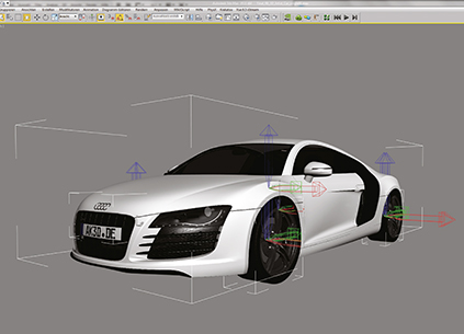
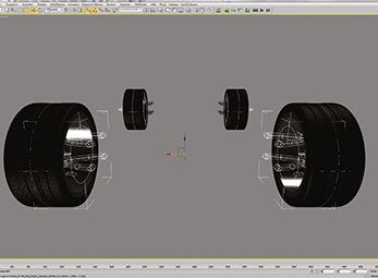
FIRST WHEEL RIG
The next step is to create the helper objects in Madcar. The first task is to isolate one wheel of the car and open the group, so that the bounding of the group box becomes selectable. Then object snap has to be activated and set to “Pivot Point”. Now you can create a Madcar “Wheel” Helper object. It can be found within the “Helper” Tab on the “Create” palette. This helper object should be created exactly on the Pivot position of the Wheel Group. Then modify the width and height to match the wheel object. Finally close the Wheel Group.
STEP 5
SECOND WHEEL RIG
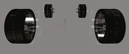
Unhide the other Wheel groups and then just copy this Madcar “Wheel” helper object to the other three Pivot positions. Then, turn the wheels on the right side around 180 degrees, so that the arrow also points to the outside. This is important as the plug-in will calculate the horizontal wheel forces too. Finally, connect all the four object groups to the helper object, to connect the motion of the Madcar System to the motion of the real 3D model.
STEP 6
FIRST SUSPENSION RIG
Now to create the suspension helper objects on the front wheels. They can be created on the pivot position of the wheels as well. The length depends on your car model. In the case of the R8, I chose 25cm. The top stop and the bottom stop are also car-dependent. In the settings select “Wheel drive” and for the “damper” preset select “Sports car”. That suspension helper Object can be instanced to the left side. Snap it on the pivot point and turn it around 180 degrees.
STEP 7
SECOND SUSPENSION RIG
Now copy one suspension object to the back of the car. It is important to copy it, as there need to be different settings on the back of the car suspension. Again snap onto the pivot points of the back wheels, instance it to the other side and again turn it around about 180 degrees. Then select “Handbrake” in the Parameters and deselect “Wheel drive” for the back wheels of the car. Now the brake system can be connected to these suspension objects.
3D car modeling with Rhinoceros is a 624-page, mplete, step-by-step guide on how to model an R8 in |h quality with mainly A-class surfaces with Rhinoceros. It is the perfect addition to this rendering tutorial as you will learn how to create a photo-realistic 3D model of a complex shaped car from just the blueprint. You will learn how to construct the whole model from scratch, up to the quality of the renderings in this tutorial. Each working step is illustrated with a screenshot, the tool used with an icon and a description of what to do. It’s available at ak3d.de as a hardcover book or as pdf file for download.
This book describes the complete modelling process for creating the R8 model with Rhinoceros. Alternatively, you can use any other car model.
STEP 8
CHASSIS WORK
Now to create a new Madcar chassis helper object. Create it on the pivot position of the 3D model's chassis. For this object it is important to have the same width and depth as the real chassis. The Z-position is also important, as this is the position of the centre of gravity of the car. As the R8 is a sports car this point is relatively flat. For any off-road cars this position can be higher. This has a great influence on the car dynamic calculations and finally the car behaviour later on.
LOCK THE COMPONENTS
Create a “Madcar” Helper object on the Pivot position of the chassis. The size is not important this time, it is just an object where most MadCar Dynamic Settings are reachable. In the options of that object, ensure the “Gravity” setting is 9.81 m/s2. Then click on “Lock components” to connect all structural part together and to check and finalise the helper setup.
STEP 10
FIRST TEST DRIVE
Now comes the fun part of creating a car animation: the driving. Create a plane first, maybe with some small noise 3D displacement added. This surface should be put under the car’s ground position. Then, on the Madcar settings, click on “Surface” and select this plane. A second click on “Update Surface” refreshes the model. Now create a camera in the back of the car and connect it to the Chassis Helper object. Finally connect your game controller, switch to the camera viewport and just click on “Drive”.
STEP 11
FINE TUNING
After the first test drive it may be necessary to optimise the physical behaviour of the car. This can easily be done with the “Damper” Settings Tools. It’s a really cool feature as it even visualises the changes of the settings. You can clearly see what happens if you change any of the damper settings. This setting alters the whole behaviour of the car as every behaviour while braking, turning, etc. depends on how the suspension works.
STEP 12
SECOND TEST DRIVE
After tuning the damper and Madcar settings, you should make some more test drives to check the behaviour of the car under different conditions – on flat ground, on bumpy ground under speed and under slow conditions. Also, make some handbrake turns to check the grip of the wheels. At this point you should clearly have the whole animation in mind. If all the required scenes are possible with the setup, you can go to the next step.
STEP 13
BUILDING THE TRACK
At this point you need to decide between building a track to drive on or simply drive on a plane and then build the track afterwards. For the animation on my website I chose the second option, as it was quite difficult to drive a 3 minute sequence at once and keep on the track without any cuts. So, with specific manoeuvres in mind, I drove on a rough plane and created the track afterwards. After making that trip on the plane, the drive was fixed and it was easy to style the track with interesting objects.
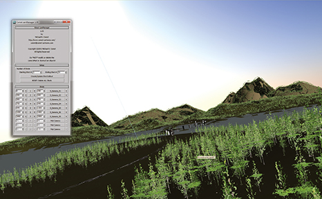
STEP 14
CREATING THE LANDSCAPE
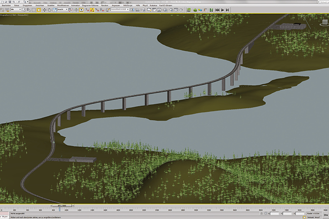
After finalising the track it’s time to add interesting elements to the drive. In my case I modelled a bridge, a sea and a landscape with more than 80 million polygons of trees with e-on Vue xStream which works as a plug-in to 3ds Max. For the start I wanted to have a kind of construction hall that opened the door and the car drove out. Then I wanted to have some good views over a seaside with some sunny effects on it and finally I wanted to have the car come to rest in a parking garage. Some of those objectives were in mind while making the drive animation, making it easy to synchronise them after the animation was done.

CAMERA SETUP
To get really good camera movements usually requires a camera rig. There are a lot of possibilities within 3ds Max to create an action-ready camera rig. There were some fixed cameras on the track as well as nearly 15 cameras linked to the car chassis itself. If the camera movements are set to be sticky to the chassis, you can deal with positional feather constraints within Max. Then the camera is linked, like on a flexible rig that makes all movements of the linked objects just some seconds later. In this way sequences become more natural and dynamic.
STEP 16
SWITCHING DIFFERENT VIEWS
A difficult part of the animation is to evaluate the whole sequence with cuts before any material is rendered. Normally a real camera team would take a lot of film material. Then afterwards, while cutting, that really huge amount of film material will be edited down to the 3 minute sequence. Some 90 per cent of the filmed material will usually be thrown away. With rendering you don’t have this luxury. Every frame rendered should be used later on. So, cutting and filming have to happen at the same time. A very handy script for that purpose is the Camera Manager of Michael Coment.
STEP 17
RENDERING THE SEQUENCE
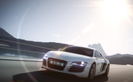
Finally it’s time to render the entire sequence. For a fast moving object like a car it is essential to render the scene with motion blur. It’s important to get spinning wheels to create a believable scene. A typical video camera has a shutter speed of 1/50th second. It is possible to calculate how often a wheel turns when filming a car driving at around 160 km/h. The spokes of the rims will nearly become invisible and it is necessary to calculate a lot of frames just to get a believable wheel rotation rendered.
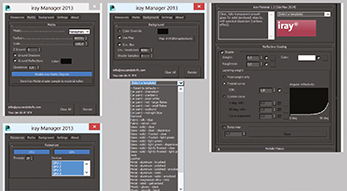
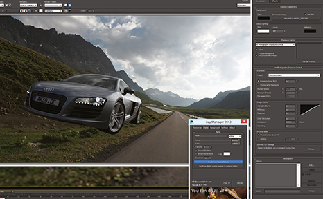
DOWNLOADING THE TOOLS
In this step two helper tools need to be downloaded and installed. The first is the iRay Manager script that can be downloaded here: http://www.youcandoitvfx.com/?page_id=12. With this tool installed it’s easy to set up whether to render using the CPU, GPU or both. There’s also access to a special HDRI projection mode that is not accessible inside Max at the moment. The second tool required for good car renders is the iRay Material 1.3 from here: ftp://ftp.nvidia-arc.com/pub/iray_material_plugin_1.3_Max2014.zip. This is a material plug-in special for iRay that makes layered materials available. It provides a huge bunch of material presets and also presets for car paints!
STEP 19
BASE SCENE SETUP
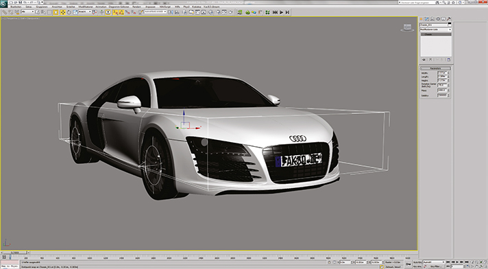
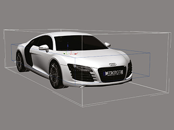
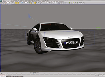
First of all, we import or open the car model. In my case I used the final 3D model from my tutorial Book 3D car modeling with Rhinoceros (http://www.ak3d.de/all/3d_car_tutorial_book_animation). The finished 3D model is also available there. Alternatively you can use any other car model as well. Group the model into five groups consisting of the chassis and the four wheels. After placing the pivot point of the front wheels correctly, turn the wheels for a perfect pose for rendering. Finally, create an omni light that is switched off. This turns the standard light function from 3ds Max off.
STEP 20
IRAY MATERIAL SETUP
For faster material placement put the different car parts on different layers with their material name as layername (paint, metal, alu, black plastic and so on). Then open the Material editor and open the map/material browser and search for the iRay Material. Then choose a preset that comes next to the material layer and fine tune the parameters. For example, select the preset “red car paint” and change the colour to grey. Then select the objects on the layer and assign the material to that layer. We repeat this step for every single material layer.
PIMP MY RIDE
The physical setup of a car is not easy at all. For an animation project like the one I did for the R8 animation (www.ak3d.de), you have to find a setup with all scenes possible that you have in mind. This can be really time consuming. In my case I wanted to have this u-turn at the beginning of the animation. So, I had to deal with the weight of the car and all other parameters of the car until this scene was possible. I made the animation without any landscape first, and then created the world around this trip. For me this was the most straightforward method of creating the whole animation. R&D will release the iCars Vol.1 collection. These are finished modelled, rigged and tuned models, ready to use with Madcar without any setup. With that, a lot of time for test drives and fine tuning can be saved.
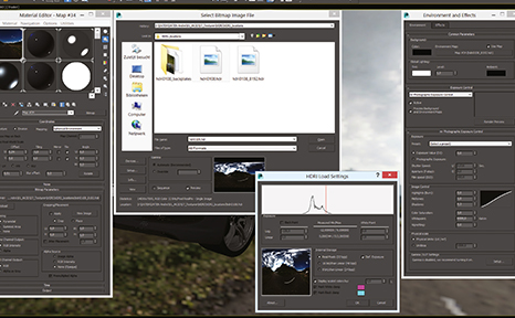
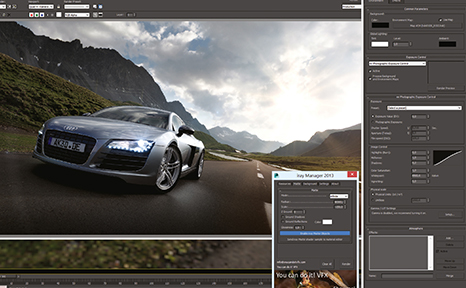
HDRI SETUP AND EXPOSURE CONTROL
Open the Environment Dialog, choose Use map and select a bitmap slot. Drag this Bitmap slot to a Material editor field and select a HDRI in the browser field. For the colour, choose Real pixel 32-bit and leave the values as they are. Then switch the projection mode to Hemisphere and close the Material editor. In the exposure settings choose the Mental Ray photographic exposure tool and click on checkbox for “Affect maps and environment”. Then click into a viewport and press Alt-B to open the viewport background menu to see the environment map.
STEP 22
RENDERING AND FINE TUNING
Now to finally start rendering the scene. For this, open up the environment dialog and the Material editor and start to fine tune all settings. First look at the HDRI background and set up the exposure level to a nice value so that the details of the background picture stay visible. Then set up the white point and contrast settings until the picture looks right. You can even add a vignette effect at this stage. As soon as the background is correct, start to fine tune the iRay material settings. Just change the settings and re-render the scene until each material looks as good as possible.
STEP 23
FINAL RENDERING SETTINGS
Finally, time for a very handy trick. Start the iRay Manager script and switch the projection mode to Hemisphere. Tick on the boxes for “shadow ground” and “glossy ground”. This finally transforms the HDRI image so that the car stands on the ground with a correct shadow and even reflection on the street! Then fine tune the values for Ground scale, Environment scale and the Reflection glossiness and render the scene constantly until the picture looks perfect. Lastly, render the scene as a HDR file and chose a good sampling value like 2000. From that point on, the next steps can be done in Photoshop or After Effects.
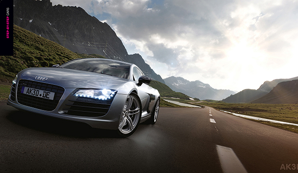
AUDI A8 BY ANDRÉ KUTSCHERAUER |
|