Chapter Twelve. Spaceway and the Global Broadcast Service
Most of this book has been about direct broadcast satellite (DBS) communications. This is a telecommunications broadcast medium that is called a point-to-multipoint transmission. In other words, a single uplink (Castle Rock, Colorado, for DIRECTV; Cheyenne, Wyoming, for EchoStar; and so on) transmits to millions and potentially tens of millions of receivers in the United States. However, there is no way for the subscriber to communicate back with the uplink.
Note that there is a communication capability in the IRD (see Chapter 11) for the report-back feature. However, this is controlled by DIRECTV and not the subscriber. Further, the communication is very asymmetric; the communication to the subscriber is wideband while the backlink is very narrowband.
A number of potential applications require two-way or duplex communication. For example, a video teleconference is not of much value if only one of the parties can be seen; thus, there is a need for wideband point-to-point communications. The Hughes Spaceway Satellite was conceived to fill these needs.
Anecdotal Note: In the early 1990s when Spaceway began, Dr. Harold A. Rosen was a new grandfather. Video phones had small screens, terrible quality, and limited viewing angles. Harold believed there should be a capability for much higher quality so that people could dial the party they wanted to reach and be able to have an audio/video conversation. We designed the first implementation of this in my studio, and the project quickly became known as the Grandparent Project. As time went on, Hughes developed the business case, and so forth, Spaceway became the name, but it had its genesis in Harold’s Grandparent Project [Fitzpatrick95].
12.1 Spaceway Overview
Spaceway is designed to provide the point-to-point capability previously mentioned. It is planned to operate in the Ka-Band, which generally means that the uplink is at 30 GHz and the downlink is at 20 GHz [Careless96]. Hughes’s studies have shown that a 26-inch-diameter antenna can provide reliable transceiver capabilities. The Spaceway satellite will be an enhanced version of the body-stabilized satellite used for DBS (see Figure 12.1). Space-way will employ multiple spot beams, as shown schematically in Figure 12.2 for coverage of North America.
Figure 12.1 Spaceway Satellite

Figure 12.2 Spaceway Frequency Reuse

Each of the satellites will provide a total of 48 125-MHz spot beams (24 beams used on opposite circular polarizations) for uplink and downlink transmissions. In this way, each satellite effectively reuses the 500 MHz of spectrum assigned to it about 12 times. The original Hughes application to the FCC in December 1993 was for a two-satellite architecture that would be located at 101° W longitude and service the United States.
The key to the bandwidth-on-demand capability of the system is the onboard switching. Figure 12.3 is a block diagram of the satellite-switching subsystem. In it each of the 24 locations that receive spot beams is separated into its left-hand circularly polarized (LHCP) and right-hand circularly polarized (RHCP) components. Each of these components then is amplified by a low-noise amplifier (LNA), downconverted, and channelized. Next, the channelized outputs are demodulated and demultiplexed. At this point, the signals can be routed to the correct transmit spot beam.
Figure 12.3 Onboard Communications System

Each of the downlink channels is QPSK modulated and amplified, then the two polarizations are combined to form the 24 downlink spot beams. The fact that the uplink signal is completely demodulated and that the forward error correction is removed means the signal is completely regenerated in the satellite. Thus, the uplink and downlink are completely decoupled. This is particularly advantageous in a duplex situation where the transmitters can be small terminals.
12.2 Global Spaceway
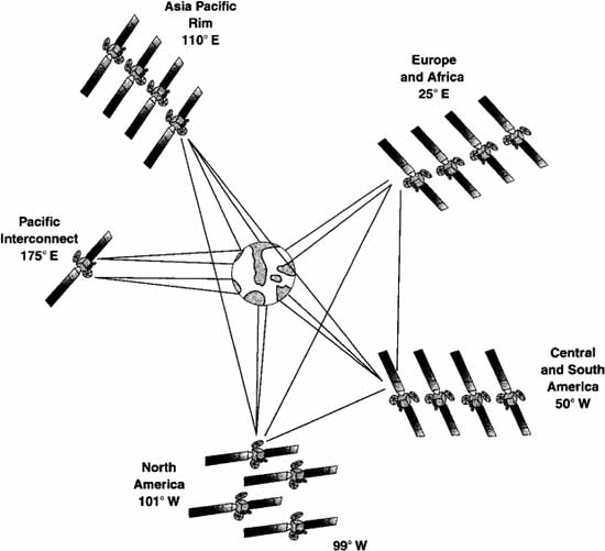
As the Spaceway concept continued to evolve at Hughes, it became clear that the Spaceway should be a global system. Thus, on July 26,1994, Hughes filed an amended application for a Global Spaceway system, which is to be implemented in two phases.
The first phase is a 9-satellite system, shown in Figure 12.4. As can be seen from the figure, North America is served by two satellites at 101° W longitude. The Pacific Rim is served by two satellites at 110° E longitude, Europe and Africa by two satellites at 25° E longitude, and South and Central America is served by two satellites at 50° W longitude. The ninth satellite at 175° E is called the Pacific Interconnect satellite and is to handle the large volume of traffic between Asia and the United States.
Figure 12.4 Spaceway Global Network—Phase 1 Orbital Locations

A study of Figure 12.4 shows that in addition to the ground beams, lines are drawn from each of the four pairs of satellites to each of the other three pairs. These represent intersatellite links (ISLs) that permit point-to-point communications when the two points are not within the footprint of a single
satellite, without an additional ground hop. Figures 12.5a, b, c, and d show the spot beam patterns for the first phase.
Figure 12.5a Phase 1, North America—Satellites 1 and 2
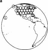
Figure 12.5b Phase 1, Central and South America—Satellites 1 and 2

Figure 12.5c Phase 1, Europe and Africa—Satellites 1 and 2

Figure 12.5d Phase 1, Asia Pacific Rim—Satellites 1 and 2

All the beams shown in Figures 12.5a-d are narrow-spot beams of 1 degree that have a 650-kilometer diameter at the Earth’s surface. With 20-watt TWTAs, the EIRP at the spot-beam center is 59 dBw. In these narrow-spot beams, the G/T is 18.9 dB/K at the center of the spot beam and 13.9 dB/K at the edge of coverage.
The ISLs will be at a frequency of about 60 GHz. At these frequencies there is essentially 100 percent absorption by the Earth’s atmosphere, so there is negligible effect on other services from the Spaceway.
Phase 2 of the Global Spaceway is to add eight satellites, essentially with four pairs of satellites joining the original four pairs. The lone exception is for North American coverage where the new pair is located at 99° W longitude rather than 101°. Figure 12.6 shows this final architecture.
Figure 12.6 Global Spaceway Phase 2 Orbital Locations
Figures 12.7a, b, c, and d show the spot-beam patterns for the four sets of four satellites. A look at Figures 12.7a-d shows a mix of narrow-diameter spot beams and larger spot beams. In general, the larger beams are used to cover parts of the world with low population density. The larger spot beams are 3 degrees in beam width and have a 1,950-kilometer diameter at the Earth’s surface.
Figure 12.7a Phase 2, North America
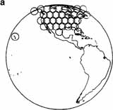
Figure 12.7b Phase 2, Central and South America

Figure 12.7c Phase 2, Europe and Africa

Figure 12.7d Phase 2, Asia Pacific Rim

The larger-diameter spot beams use a 60-watt TWTA and have an EIRP of 52 dBw at beam center. The G/T for the larger spot beam is 7.4 dB/K at beam center and 2.4 dB/K at the edge of coverage.
Consider the connectivity just indicated and the fact that the Spaceway will be able to transmit a high-resolution X-ray in less than 8 seconds that now takes 21 minutes, all with a terminal costing less than $1,000. Clearly, Spaceway is expected to be as revolutionary as DBS.
12.3 The Global Broadcast Service
DBS has major military implications. In modern warfare, information is power and the ability to communicate in hundreds of megabits per second is real power. The problem with commercially available DBS is that the EIRP is matched to locations where revenue-producing humans can receive the services (not fish in the oceans, for example).
The solution to this problem is movable-spot beams. In the Global Broadcast Service (GBS) Phase 2, under contract with the U.S. Navy, Hughes is modifying the last three satellites of the UHF follow-on satellite series to have a DBS capability with movable-spot beams. Each satellite will have four transponders and three movable spot beams: two with a 500-nautical-mile diameter and one with a 2,000-nautical-mile diameter.
Phase 2 of the GBS is to be operational during 1999 and will give the U.S. military an unprecedented ability to communicate worldwide.
References
[Careless96] Careless, James, Ka-Band Satellites: A Guide to the Proposed U.S. Systems. Via Satellite, February 1996.
[Fitzpatrick95] Fitzpatrick, Edward, Spaceway: Providing Affordable and Versatile Telecommunication Solutions, Pacific Telecommunications Review 17(1), September 1995.