
Appendix B. QPSK Modulation and Demodulation
Modulation is a process whereby an information signal modifies a second signal called the carrier. In demodulation, the information signal is recovered from the modulated carrier.
Since most carriers are sinusoids, we can write the carrier as
![]()
Various modulation schemes have been designed to vary A (amplitude modulation), ωc (frequency modulation), or ø (phase modulation). Varying ωc or φ is sometimes called angle modulation. Note that with angle modulation, the amplitude of the modulated carrier does not vary. This leads to the language that an angle-modulated carrier has constant envelope.
In analog modulation, the signals for A, ωc, or ø are usually the information signal or some modification of it. During demodulation, the information signal must be recovered from the modulated carrier, usually in the presence of noise. This recovery of the information signal is mathematically an estimation theory problem.
B.1 Digital Modulation
In digital modulation, the transmitter selects and transmits one of a finite set of messages (m1, m2, … , mN). Each message is represented by a unique waveform. Once again, A, ωc, or ø (or combinations thereof) can be varied.
The problem of the demodulator, then, is to select which of the possible messages was most likely to have been sent. Note that this is a decision theory problem.
B.2 The Satellite Channel
The satellite channel, especially above 10 GHz, is characterized by wide variations in amplitude (A). The best solution is to amplify the signal, limit it, and then bandpass the result to recover a fixed-amplitude replica of the original. The limiting process intrinsically eliminates any information carried in A. Thus, high spectral-efficiency techniques such as quadrature amplitude modulation (QAM), which is a combination of amplitude and phase modulation, cannot be used.
In principle, one might design an automatic gain control (AGC) system that would permit an amplitude component. However, this AGC would have to respond in a fraction of a symbol period and operate above 10 GHz. The author is unaware of any system of this type that has been successfully implemented.
B.3 M-ary Phase Shift Keying
M-ary Phase Shift Keying (MPSK) can be represented by
![]()
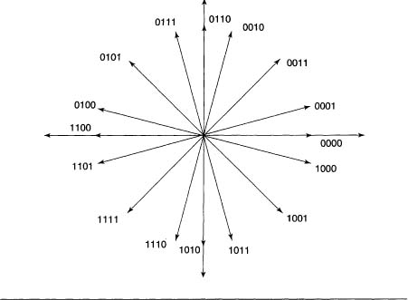
M is normally a power of 2, but doesn’t have to be. M = 2 is called Binary Phase Shift Keying (BPSK), and M = 4 is called Quatenary Phase Shift Keying (QPSK). MPSK for M = 2, 4, 8, and 16 is shown in Figures B.1, B.2, B.3, and B.4, the constellations for M-ary PSK.

Figure B.2 QPSK
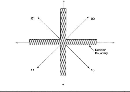
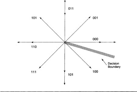
Figure B.4 16M-aryPSK
Note that by using a Grey code for the states, the probability of a bit error is approximately
![]()
where Ps is the probability of symbol error. This is true because the most likely symbol error is to an adjacent point in the constellation.
B.4 DBS Modulation and Demodulation
All the known DBS systems use QPSK (Figure B.2), so a brief description of QPSK follows.
B.4.1 Filtering
The Power Spectral Density (PSD) for QPSK is of the form
![]()
with the first null at the symbol rate and significant energy extending for multiples of the symbol rate on both sides of the center frequency. This is unacceptable because energy from one transponder will interfere with the transponder on either side of it.
The solution selected by all DBS systems is to filter the baseband signal. The filter of choice is a raised cosine filter of the form
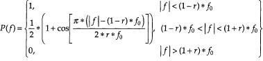
The parameter r is called the roll-off factor and is 0.35 for all known DBS systems. The frequency f0 equals the low-pass bandwidth and is usually chosen as 13 MHz for a 24-MHz bandwidth transponder.
B.4.2 Modulation
QPSK can be visualized and implemented by adding two BPSK signals, one of which is rotated 90 degrees with respect to the other. This is shown in Figure B.5.
Figure B.5 QPSK Modulator

B.4.3 Demodulation
The maximum likelihood demodulator is shown in Figure B.6. It should be noted that for soft decision output, analog-to-digital converters must replace the circuits labeled ‘decision circuit.’
Figure B.6 QPSK Demodulator
