
Chapter Four. Key Elements of the Radio Frequency Subsystem
4.1 Introduction
Many of the components shown in Figure 3.1 are standard in the satellite communication business and will not be discussed in this book. However, the shaped reflector antenna, modulation (important for establishing the overall DBS performance), Low Noise Block (LNB), and Traveling Wave Tube Amplifier (TWT-A) are key radio frequency (RF) subsystems and will be discussed individually in this chapter.
4.2 The Shaped Reflector Antenna
Appendix A shows that the rain-fades vary widely throughout the United States. This means that if nothing special were done, areas receiving high rainfall would have unacceptable service because of numerous service outages.
One of the early ideas was to use larger antennas in the higher rainfall areas. However, with a population mobility of 10 percent in the United States, someone from a dry area might move to a wet area and would be very unhappy because his or her service quality would go down. Furthermore, having multiple size antennas would create manufacturing complications. The solution was the highly innovative shaped reflector antenna.
Most of us have gone to an amusement park Fun House where oddly shaped mirrors distort our appearance. The concept behind the shaped antenna reflector is similar: the reflector is shaped to create more energy in some parts of the beam and less energy in other parts.
Before the invention of the shaped reflector, antenna designers had to shape the transmitted beam by an arrangement of feed horns. These feed horns had to be excited in proper phase and amplitude by a complex beam-forming network.
As customer requirements have grown, so too has the complexity of the beam-forming network and the horn arrays. The increased complexity adds mass to the satellite. This increases the launch cost from $25,000 to $50,000 per pound. The early DIRECTV antenna design had about 120 feed horns, each of which had to be fine-tuned to maintain proper amplitude and phase.
Mechanically shaping the reflector eliminated the costly feeds and the undesired extra mass. Now, the dimpling in the reflector surface substitutes for the complex multiple feed arrays in directing radiated energy in the right directions. Antenna designers have eliminated the need for all but one horn and have done away with the feed network entirely.
The remaining horn illuminates the shaped reflector to produce the desired beam coverage. The absence of the horn arrays and the beam-forming network reduces signal losses and improves antenna performance.
Analysis shows that shaped-reflector technology significantly increases its effective radiated power. Compared to a more traditional multiple-feed antenna system, the new technology reduces the weight of the antenna systems for the DBS satellites by approximately 250 pounds. Figure 4.1 shows a microphotograph of the reflector surface and a sketch of how the shaping affects the beam formation.
Figure 4.1 The Shaped Reflector Antenna Reproduced from Vectors, XXXV(3): 14, 1993. Copyright © 1993 Hughes Aircraft Co. All rights reserved. Used with permission.

Note: There is an additional benefit to the shaped reflector antenna that doesn’t affect the DBS communication system. Feed arrays usually have to be physically offset from the spacecraft structure to prevent blockage or scattering of the radiated signal from interfering with the antenna pattern. Offsetting the feed horns and feed assembly shifts the satellite’s center of gravity. This has to be corrected by a time-consuming process of balancing the satellite for a successful launch. Feed weight on satellites equipped with a shaped reflector antenna is significantly decreased. Therefore, the process of balancing the spacecraft is greatly simplified [Vectors93].
This shaping of the reflector is computed in advance according to the rainfall model for the United States to normalize the expected outage time for all areas. The probability is 0.997 that the outage will be less than 40 hours per year.
Figure 4.2 shows a relative energy given to various geographic areas in the United States. This figure can be derived from the rain model given in Appendix A and the DBS parameters.
Figure 4.2 Required Rain Margins for the United States Reproduced from ‘Propagation in Nonionized Media,’ ITU-R Rec. PN.837-1, 1994 PN Series. Used with permission of ITU, Geneva, Switzerland.

4.3 Modulation and Demodulation
Modulation refers to the way that information is imparted to an RF carrier. In analog communication systems, the modulation is amplitude, frequency, or phase, and these entities are allowed to vary continuously. In a digital communication system, the information is Is and Os; however, we cannot radiate Is and Os directly. Therefore, the Is and Os are used to modulate a carrier or sequence of carriers. In this digital modulation, only a finite number of states are possible each symbol time. The problem at the receiver is to determine which of the states was transmitted.
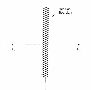
The simplest way to do this digital modulation is to represent a 1 by the cosine (ωct) and a 0 by -cosine (ωct). This is shown in Figure 4.3. Also shown in this figure is a decision boundary that corresponds to the y-axis. If the received signal falls anywhere to the left of this boundary, the signal is called a 0, otherwise it is called a 1. This type of modulation is called Binary Phase Shift Keying (BPSK). The time it takes each of the two possibilities to be transmitted is called a symbol time. One bit of information is transmitted during this symbol time.
Figure 4.3 Binary Phase Shift Keying
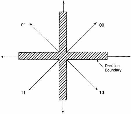
However, we can convey more than one bit of information per symbol. Perhaps the most popular way to do this is with QPSK. With QPSK, the carrier can assume one of four possible phases, as shown in Figure 4.4. Each of the carrier positions can be described by cosine [wt * t + j * π/2], j = 0,1,2,3. It should be clear that each position of the carrier represents two bits. Thus, QPSK permits the transmission of two bits per symbol, or twice as much information per symbol as BPSK. Appendix B shows how QPSK modulators and demodulators can be implemented.
Figure 4.4 Quaternary (Quadrature) Phase Shift Keying
It should be clear that we can continue this process by using 8 carrier states (8-ary), which yields three bits per symbol, or even using 16 carrier states (16-ary), which gives four bits per symbol. However, the hardware complexity increases and, worst of all, the required antenna diameters increase significantly.
4.4 The Low-Noise Block
As noted in Chapter 2, the downlink frequency for DBS is 12.2 to 12.7 GHz. At this frequency, signal degradation is sufficiently high so that attempts to put the signal on any length of coaxial cable will not work. Thus, a way has to be found to lower the frequency before it is sent from the Outdoor Unit (ODU) to the Indoor Unit (IDU). This function is performed by the LNB.
In Figure 4.5, the LNB is the device that is located at the offset focus of the reflector. Figure 4.6 is a block diagram of the LNB. Starting from the left of the figure, the low-noise amplifier amplifies the received signal. This signal is then multiplied by a signal from the local oscillator (lo), which operates at a frequency of 12,262 MHz. Since the sin(ωst) * sin(ωlot) = sin{(ωs + ωlo)t} + sin{(ωs-ωlo)t} the output of the mixer contains the sum and the difference of the two frequencies.
Figure 4.5 LNB Mounted on Antenna (Outdoor Unit)
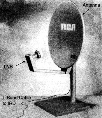
Figure 4.6 LNB Block Diagram

The local oscillator frequency was selected such that the difference frequency would fall in the range of 950 MHz to 1,450 MHz (L-Band). A bandpass filter selects this difference frequency, which is then amplified by the distribution amplifier, that drives the coaxial cable from the LNB to the settop box (IRD).
4.5 Traveling Wave Tube Amplifier
Traveling wave tube amplifiers are used for the DBS satellite high-power amplifiers. The DBS satellites use 120-watt TWT-As. Two of them can operate in parallel to create the 240-watt transponder mode.
Figure 4.7 is a schematic of a TWT-A. The heater, cathode, focusing electrodes, and collectors form an electron beam. The RF signal to be amplified is coupled into a helix through which the electron beam passes. A traveling wave is set up along the helix. This traveling wave interacts with the electron beam, which converts energy from the electron beam into the RF signal. Thus, the RF output signal is an amplified version of the input. Power from the solar panel (or batteries) provides DC power for the electron beam and hence to the RF power out. The efficiency of this process is 65 percent.
Figure 4.7 Traveling Wave Tube Schematic Reproduced from TWT/TWTA Handbook, p, 66. Copyright © 1992, Hughes Aircraft Co. Used with permission.

References
[Ha90] Ha, Tri, Digital Satellite Communication, New York: McGraw-Hill, 1990.
[Hughes92] TWT and TWTA Handbook, Hughes Aircraft Company, Torrance, CA, 1992.
[Hughes93] Hughes Electronics, Vectors, XXXV(3), Hughes Aircraft Company, Torrance, CA, 1993.