Chapter Three: Layers, Colors, and Linetypes
Chapter Objectives
Introduction
CAD is much more than a computerized way to do drafting. CAD programs have many powerful features that have no parallel in manual drawing. Layering is a good example. Layers are like transparent overlays that can be added to or peeled away from a drawing. Layers are used to separate different aspects of a drawing so that they can be treated and presented independently. Layers exist in the same space and in the same drawing but can be set up and controlled individually, allowing for greater control, precision, and flexibility. In this chapter, you create and use four new layers, each with its own associated color and linetype.
layer: In CAD practice, a layer is defined with colors, linetypes, and lineweights so that objects of a certain type can be grouped together and treated separately from other types of objects.
The ZOOM command is another bit of CAD magic, allowing your drawings to accurately represent real-world detail at the largest and smallest scales within the same drawing. In this chapter, you also learn to use the FILLET and CHAMFER commands on the corners of previously drawn objects and to move between adjacent portions of a drawing with the PAN command. All these new techniques add considerably to the professionalism of your developing CAD technique.
Creating New Layers
Layers allow you to treat specialized groups of entities in your drawing separately from other groups. For example, you can draw dimensions on a special dimension layer so that you can turn them on and off at will. You can then turn off the dimension layer to prepare drawings that are shown without dimensions. When a layer is turned off, all the objects on that layer become invisible, although they are still part of the drawing database and can be recalled at any time. In this way, layers can be viewed, edited, manipulated, and plotted independently.
Layer |
|
|---|---|
Command |
Layer |
Alias |
La |
Panel |
Layers |
Tool |
|

Tip
A general procedure for creating a layer is:
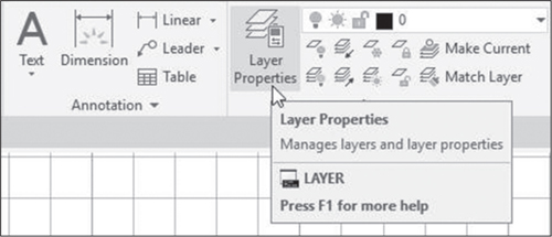
Select the Layer Properties tool from the ribbon.
Click the New Layer icon.
Type in a layer name.
Repeat for other new layers.
Close the Layer Properties palette.
It is common practice to put dimensions on a separate layer, but there are many other uses of layers as well. Fundamentally, layers are used to separate colors and linetypes, and these, in turn, take on special significance, depending on the drawing application. It is standard drafting practice, for example, to use small, evenly spaced dashes to represent objects or edges that would, in reality, be hidden from view. On a CAD system, these hidden lines can be put on an independent layer so they can be turned on and off and given their own color to make it easy for the designer to remember what layer he or she is working on.
In this chapter, we present a simple layering system. You should remember that there are countless possibilities. AutoCAD allows a full range of colors and as many layers as you like.
You should also be aware that linetypes and colors are not restricted to being associated with layers. It is possible to mix linetypes and colors on a single layer. Although this might be useful for certain applications, we do not recommend it at this point.
✓ Create a new drawing by opening the Start file tab, checking to see that acad is selected in the template list, and picking the Start Drawing button.
✓ If necessary, turn on the Grid Display.
✓ Type z <Enter> to enter the ZOOM command and then a <Enter> to zoom all.
The Layer Properties Manager Palette
The creation and specification of layers and layer properties in AutoCAD is handled through the Layer Properties Manager palette. Palettes are like dialog boxes but they are laid out differently and have some different features. The Layer Properties Manager palette consists of a table of layers. Clicking the appropriate row and column changes a setting or takes you to another dialog box where a setting can be changed.
✓ Select the Layer Properties tool from the ribbon, as shown in Figure 3-1.
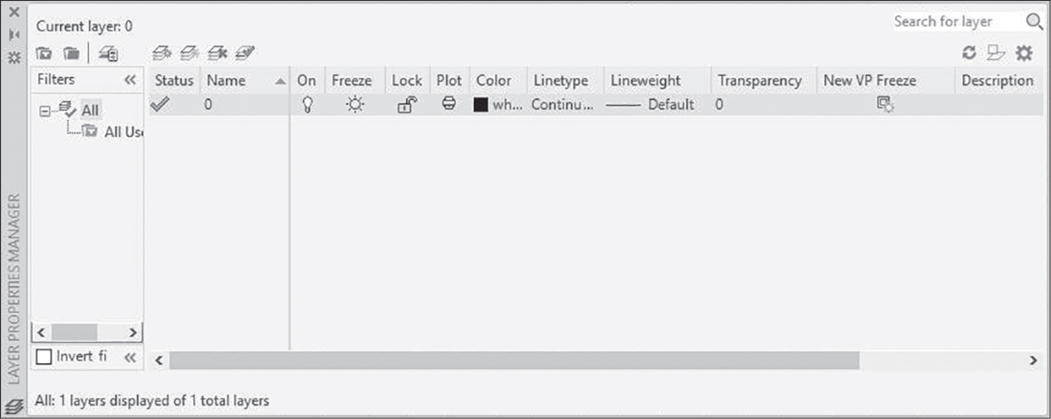
This opens the Layer Properties Manager palette illustrated in Figure 3-2. The large open space to the right shows the names and properties of all layers defined in the current drawing. Layering systems can become very complex, and for this reason there is a system to limit or filter the layer names shown on the layer list. This is controlled by the icons at the top left. With no filters specified, the layer list shows all used layers. Currently, 0 is the only defined layer. The icons on the line after the layer name show the current state of various properties of that layer. We get to these shortly.
Now, we will create three new layers. AutoCAD makes this easy.
✓ Pick the New Layer icon, as shown in Figure 3-3.
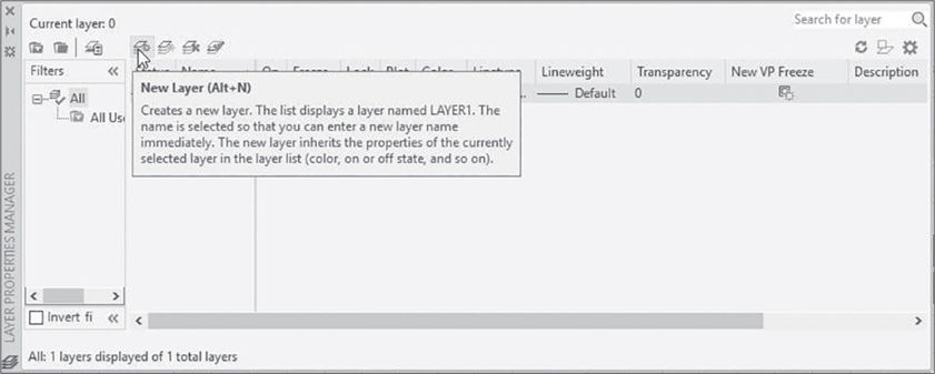
A newly defined layer, “Layer1,” is created immediately and added to the Layer Name list box. The new layer is given the characteristics of Layer 0. We alter these in the “Assigning Colors to Layers” section. First, however, we give this layer a new name and then define three more layers.
Layer names can be long or short. We have chosen single-digit numbers as layer names because they are easy to type, and we can match them to AutoCAD’s index color numbering sequence.
✓ Type 1 for the layer name.
Layer1 changes to simply 1. It is not necessary to press <Enter> after typing the name.
✓ Pick the New Layer icon again.
A second new layer is added to the list. It again has the default name Layer1. Change it to 2.
✓ Type 2 for the second layer name.
✓ Pick the New Layer icon again.
✓ Type 3 for the third layer name and press <Enter> to complete the process.
At this point, your layer name list should show Layers 0, 1, 2, and 3, all with identical properties.
Assigning Colors to Layers
We now have four layers, but they are all the same except for their names. We have more changes to make before our new layers have useful identities.
Layer 0 has some unique features, which are not introduced here. Because of these, it is common practice to leave Layer 0 defined the way it is. We begin our changes on Layer 1.
✓ In the Layer Properties Manager palette, pick the white square under Color in the Layer 1 line.
Picking the white square in the Color column of Layer 1 selects Layer 1 and opens the Select Color dialog box illustrated in Figure 3-4. The three tabs in this dialog box show three ways in which colors can be defined in AutoCAD. By default, the Index Color tab is probably selected, as shown in Figure 3-4. The Index Color system is a simple numbered selection of 255 colors and shades. The True Color and Color Books systems are standard color systems commonly used by graphic designers. The True Color tab can be set to access either the Hue, Saturation, and Luminance (HSL) color model or the Red, Green, Blue (RGB) model. Both of these systems work by mixing colors and color characteristics. The Color Books tab gives access to DIC, Pantone, and RAL color books. These standard color sets are also numbered, but they provide many more choices than the AutoCAD index color set. In this chapter we confine ourselves to the Index Color tab.
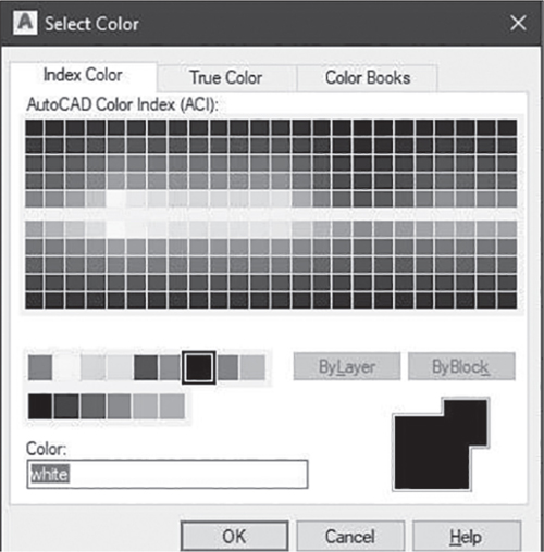
✓ If necessary, click the Index Color tab.
The Index Color tab shows the complete selection of 255 colors. At the top is a full palette of shades 10 through 249. Below that are the nine standard colors, numbered 1 through 9, followed by gray shades, numbered 250 through 255.
✓ Move your cursor freely inside the dialog box.
When your cursor is on a color, it is highlighted with a black and white border.
✓ Let your cursor rest on any color.
Notice that the number of the color is registered under the palette next to the words Index color. This is the AutoCAD index color number for the color currently highlighted. Notice also the three numbers on the right following the words Red, Green, Blue. This is the RGB color model equivalent. RGB colors are combinations of red, green, and blue, with 255 shades of each.
✓ Pick any color in the palette.
When a color is selected, it is outlined with a black border, and a preview “patch” is displayed on the bottom right of the dialog box against a patch of the current color for comparison. The color is not actually selected in the drawing until you click OK to exit the dialog box. For our purposes, we want to select standard red, color number 1 on the strip in the middle of the dialog box.
✓ Move the white cursor box to the red box, the first of the nine standard colors in the middle of the box.
Notice that this is index color number 1, and its RGB equivalent is 255,0,0—pure red with no green or blue added.
✓ Pick the red box.
You should see the word red and the color red shown in the preview area at the bottom of the dialog box. Note that you can also select colors by typing names or numbers directly in this edit box. Typing red or the number 1 is the same as selecting the red color box from the chart.
✓ Click OK.
Layer 1 is now defined with the color red in the Layer Name list box.
Next we assign the color yellow to Layer 2.
✓ Pick the white square under Color in the Layer 2 line, and assign the color yellow, color number 2, to Layer 2 in the Select Color dialog box. Click OK.
✓ Select Layer 3 and set this layer to green, color number 3.
Look at the layer list. You should now have Layers 0, 1, 2, and 3 defined with the colors white, red, yellow, and green.
Assigning Linetypes
AutoCAD has a standard library of linetypes that can easily be assigned to layers. There are 46 standard types. In addition to continuous lines, we use hidden lines and centerlines. We put hidden lines in yellow on Layer 2 and centerlines in green on Layer 3. Layers 1 and 0 retain the continuous linetype.
The procedure for assigning linetypes is almost identical to the procedure for assigning colors, except that you have to load linetypes into the drawing before they can be used.
✓ In the Layer Properties Manager palette, pick Continuous in the Linetype column of the Layer 2 line.
This selects Layer 2 and opens the Select Linetype dialog box illustrated in Figure 3-5. The box containing a list of loaded linetypes currently shows only the continuous linetype. We can fix this by clicking the Load button at the bottom of the dialog box.
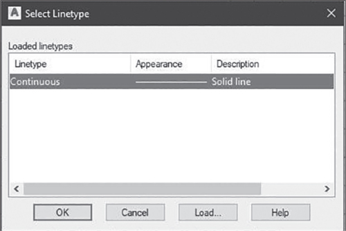
✓ Click Load.
This opens the Load or Reload Linetypes dialog box illustrated in Figure 3-6. Here you can pick from the list of linetypes available from the standard acad file or from other files containing linetypes, if there are any on your system. You also have the option of loading all linetypes from any given file at once. The linetypes are then defined in your drawing, and you can assign a new linetype to a layer at any time. This makes things easier. It does, however, use up more memory.

For our purposes, we load only the hidden and center linetypes we are going to be using.
✓ Scroll down until you see the linetype labeled CENTER.
✓ Click CENTER in the Linetype column at the left.
✓ Scroll down again until you see the linetype labeled HIDDEN.
✓ Hold down the <Ctrl> key and click HIDDEN in the Linetype column.
The <Ctrl> key lets you highlight two separate items in a list.
✓ Click OK to complete the loading process.
You should now see the center and hidden linetypes added to the list of loaded linetypes. Now that these are loaded, we can assign them to layers.
Note
Make sure that you actually click the word Continuous. If you click one of the icons in the Layer 2 line, you might turn the layer off or freeze it so that you cannot draw on it. These properties are discussed at the end of the “Changing the Current Layer” section.
✓ Click HIDDEN in the Linetype column.
✓ Click OK to close the dialog box.
You should see that Layer 2 now has the hidden linetype.
Next, we assign the center linetype to Layer 3.
✓ Click Continuous in the Linetype column of the Layer 3 line.
✓ In the Select Linetype dialog box, select the CENTER linetype.
✓ Click OK.
Examine your layer list again. It should show Layer 2 with the hidden linetype and Layer 3 with the center linetype. Before exiting the Layer Properties Manager palette, we create one additional layer to demonstrate AutoCAD’s lineweight feature.
Assigning Lineweights
Lineweight refers to the thickness of lines as they are displayed and plotted. All lines are initially given a default lineweight. Lineweights are assigned by layer and are displayed only if the Lineweight button on the status bar is in the on position. In this section, we create a new layer and give it a much larger lineweight for demonstration purposes.
lineweight: A value that specifies the width at which a line will be displayed on the screen or in a printed drawing.
First, we create a new layer because we do not want to change our previous layers from the default lineweight setting.
✓ If Layer 3 is not highlighted, select it now.
✓ Pick the New Layer icon in the palette.
Notice that the new layer takes on the characteristics of the previously highlighted layer. Our last action was to give Layer 3 the center linetype, so your new layer should have green centerlines and the other characteristics of Layer 3.
✓ Type 4 for the new layer name.
✓ Click Default (or Defa …) in the Lineweight column of Layer 4.
This opens the Lineweight dialog box, shown in Figure 3-7. We use a rather large lineweight to create a clear demonstration. Be aware that printed lineweights may not exactly match lineweights as shown on the screen.
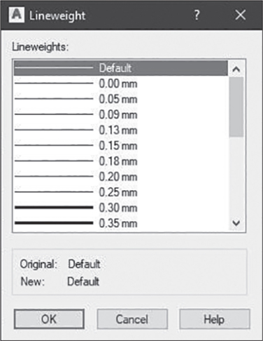
✓ Scroll down until you see 0.50 mm on the list.
✓ Pick the 0.50 mm line.
Below the list you can see that the original specification for this layer was the default and is now being changed to 0.50 mm.
Tip
Lineweight settings are most useful when correlated with plotter pen sizes, so that you control the appearance of lines in your plotted drawing. Your pen sizes may be in inches rather than millimeters. To switch from lineweights in mm to inches, use the following procedure:
Type LW <Enter>.
In the Lineweight Settings dialog box, select Inches in the Units for Listing panel.
Click OK.
✓ Click OK to return to the Layer Properties Manager palette.
It is now time to leave the dialog box and see what we can do with our new layers.
✓ Click the Close button (X) at the top left of the palette to exit the Layer Properties Manager palette.
Before proceeding, you should be back in your drawing window with your new layers defined in your drawing. To verify that you have successfully defined new layers, open the Layer drop-down list on the ribbon, as shown in Figure 3-8. Notice that this is not the label at the bottom of the Layer tab. Clicking that line will open up a tab extension.
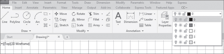
✓ To open the Layer list, click the arrow or anywhere in the list box.
Your list should resemble the one in Figure 3-8.
Changing the Current Layer
In this section, we make each of your new layers current and draw objects on them. You can immediately see how much power you have added to your drawing by the addition of new layers, colors, linetypes, and lineweights.
To draw new entities on a layer, you must make it the currently active layer. Previously drawn objects on other layers also are visible, but new objects go on the current layer.
There are two quick methods to establish the current layer. The first works the same as any drop-down list. The second makes use of previously drawn objects. We use the first method to draw the objects in Figure 3-9.

✓ Click anywhere in the Layer list box on the ribbon.
This opens the list, as shown previously in Figure 3-8.
✓ Select Layer 1 by clicking to the right of the layer name 1 in the drop-down list.
Layer 1 replaces Layer 0 as the current layer on the Layer list on the Layers panel of the ribbon.
✓ Using the RECTANG command, draw the 6 × 6 square shown in Figure 3-9, with the first corner at (3,2) and the other corner at (9,8).
Your square should show the red continuous lines of Layer 1.
✓ Click anywhere in the Layer list box.
✓ Click to the right of the layer name 2.
Layer 2 becomes the current layer.
✓ With Layer 2 current, draw the hidden circle in Figure 3-9, centered at (6,5) with radius 2.
Your circle should appear in yellow hidden lines.
✓ Make Layer 3 current and draw a horizontal centerline from (2,5) to (10,5).
This line should appear as a green centerline.
✓ Type LWD <Enter> to execute the LWDISPLAY command, which allows you to display or hide lineweight.
✓ Type on <Enter> to display lineweight.
✓ Make Layer 4 current and draw a vertical line from (6,1) to (6,9).
This line should appear as a green centerline with noticeable thickness.
✓ Type LWD <Enter>.
✓ Type off <Enter> to hide lineweight.
With Lineweight off, the lineweight of the vertical centerline is not displayed.
Making an Object’s Layer Current
Finally, we use another method to make Layer 1 current before moving on.
✓ Pick the Make Current tool from the Layers panel, as shown in Figure 3-10.
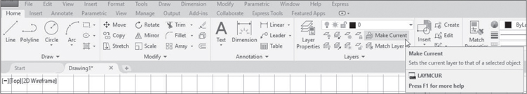
This tool allows us to make a layer current by selecting any object on that layer. AutoCAD shows the prompt:
Select object whose layer will become current:
✓ Select the red square drawn on Layer 1.
Layer 1 replaces Layer 4 in the Layer list box on the ribbon.
Other Properties of Layers
There are several other properties that can be set in the Layer Properties Manager palette or, more conveniently, in the Layer list box. These settings probably will not be useful to you in this chapter, but we introduce them briefly here for your information.
On and Off. Layers can be turned on or off with the lightbulb icon. On and off status affects only the visibility of objects on a layer. Objects on layers that are off are not visible or plotted, but are still in the drawing and are considered when the drawing is regenerated. Regeneration is the process by which AutoCAD translates the precise numerical data that make up a drawing file database into the less precise values of screen graphics. Regeneration can be a slow process in large, complex drawings. As a result, it may be useful not to regenerate all layers all the time.
regeneration: The process through which AutoCAD refreshes the drawing image on the screen by re-creating the image from the numerical database used to store the geometry of the drawing.
Freeze and Thaw. Frozen layers not only are invisible but also are ignored in regeneration. Thaw reverses this setting. Thawed layers are always regenerated but may not be represented on the screen. Freeze and thaw properties are set using the sun icon, to the right of the lightbulb icon. Layers are thawed by default, as indicated by the yellow sun. When a layer is frozen, the sun icon is replaced with a snowflake.
Lock and Unlock. Next is the lock icon. The Lock and Unlock settings do not affect visibility but do affect availability of objects for editing. Objects on locked layers are visible, but they cannot be edited. Unlocking reverses this setting.
Deleting Layers. You can delete layers using the Delete tool in the Layer Properties Manager palette. This is the red X just above the word Name. However, you cannot delete layers that have objects drawn on them. Also, you cannot delete the current layer or Layer 0.
Changing Linetype Scale
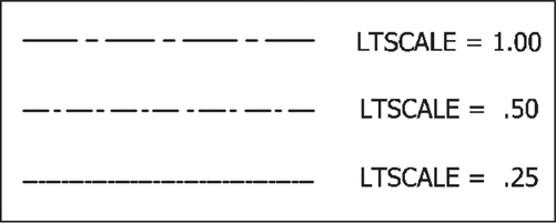
While you have objects on your screen with hidden lines and centerlines, it is a good time to demonstrate the importance of linetype scale. The size of the individual dashes and spaces that make up centerlines, hidden lines, and other linetypes is determined by a global setting called LTSCALE. By default, it is set to a factor of 1.00. In smaller drawings, this setting may be too large and cause some of the shorter lines to appear continuous regardless of what layer they are on. Or, in some cases you may want smaller spaces and dashes. To change the linetype scale, use the LTSCALE command. Try this:
linetype scale: A value that determines the size and spacing of linetype dashes and the spaces between them.
Tip
A general procedure for changing linetype scale is:
Type lts <Enter>.
Enter a new value.
✓ Type lts <Enter>.
Lts, of course, is the alias for LTSCALE.
✓ Type. 5 <Enter>.
Notice the change in the size of dashes and spaces in your drawing. Both the hidden lines and the centerlines are affected, as illustrated in Figure 3-11.
Editing Corners Using FILLET
Now that you have a variety of linetypes to use, you can begin to make more realistic mechanical drawings. Often this will require the ability to create filleted, rounded, or chamfered corners. Fillets are concave curves on corners and edges, whereas rounds are convex. AutoCAD uses the FILLET command to refer to both. Chamfers are cut on an angle rather than a curve. The FILLET and CHAMFER commands work similarly.
fillet: In drafting practice, a concave curve at the corner of an object. In AutoCAD, the term fillet and the FILLET command refer to both concave and convex curves (rounds).
round: In drafting practice, a convex curve at the corner of an object.
chamfer: An angle cut across the corner of an object.
Fillet |
|
|---|---|
Command |
Fillet |
Alias |
F |
Panel |
Modify |
Tool |
|

Tip
A general procedure for creating fillets is:
Pick the Fillet tool from the ribbon, or type f <Enter>.
Right-click and select Radius from the shortcut menu.
Enter a radius value.
Select two lines that meet at a corner.
We modify only the square in this exercise, but instead of erasing the other objects, turn them off, as follows:
✓ If you have not already done so, set Layer 1 as the current layer.
✓ Open the Layer list box on the ribbon, and click the lightbulb icons on Layers 2, 3, and 4 so that they turn from yellow to blue, indicating that they are off.
✓ Click anywhere outside the list box to close it.
When you are finished, you should see only the square. The other objects are still in your drawing and can be recalled anytime simply by turning their layers on again.
We use the square to practice fillets and chamfers.
✓ Type f <Enter>, or pick the Fillet tool from the ribbon, as shown in Figure 3-12.

On the command line, you will see options as follows:
Select first object or [Undo Polyline Radius Trim Multiple]:
Polylines are not discussed here, but we have something to show you about this option in a moment. Trim mode is discussed at the end of this exercise.
The first thing you must do is determine the degree of rounding you want. Because fillets appear as arcs, they can be defined by a radius.
✓ Select Radius from the command line options.
AutoCAD prompts:
Specify fillet radius <0.00>:
The default is 0.00.
✓ Type .75 <Enter>.
You have set 0.75 as the current fillet radius for this drawing. You can change it at any time. Changing the value does not affect previously drawn fillets.
The prompt is the same as before:
Select first object or [Undo Polyline Radius Trim Multiple]:
Notice that you have the pickbox on the screen now without the crosshairs.
✓ Pick a point on the vertical line on the right near the top corner.
✓ Move the cursor over the horizontal line at the top near the right corner.
The top line will be previewed for selection, and a preview image of the fillet will appear at the top right corner. This allows you to see what your fillet will look like before you carry out the command.
✓ Pick the horizontal line at the top near the top right corner.
Behold! A fillet! You did not even have to press <Enter>. AutoCAD knows that you are done after selecting two lines.
The Multiple Option
We use the Multiple option to fillet the remaining three corners of the square. Multiple allows you to create multiple fillets without leaving the FILLET command.
✓ Press <Enter> or the spacebar to repeat FILLET.
✓ Select Multiple from the command line options.
✓ Select two lines to fillet another corner.
You do not have to enter a radius value again because the last value is retained. Also, because you entered the Multiple option, you do not have to reenter the command. Notice again that the preview image of the fillet appeared before you selected the second line.
✓ Proceed to fillet all four corners.
When you are done, your screen should resemble Figure 3-13.

✓ Press <Enter> or the spacebar to exit FILLET.
Trim Mode
Trim mode allows you to determine whether you want AutoCAD to remove square corners as it creates fillets and chamfers. Examples of fillets created with Trim mode on and off are shown in Figure 3-14. In most cases, you want to leave Trim mode on. To turn it off, enter FILLET and select Trim and then No Trim from the command line options.

Editing Corners Using CHAMFER
The CHAMFER command sequence is almost identical to the FILLET command, with the exception that chamfers can be uneven. That is, you can cut back farther on one side of a corner than on the other. To do this, you must give AutoCAD two distances instead of one radius value.
Chamfer |
|
|---|---|
Command |
Chamfer |
Alias |
Cha |
Panel |
Modify |
Tool |
|

Tip
A general procedure for creating chamfers is:
Pick the Chamfer tool from the Fillet flyout on the ribbon.
Right-click and select Distance from the shortcut menu.
Enter a chamfer distance.
Enter a second chamfer distance or press <Enter> for an even chamfer.
Select two lines that meet at a corner.
In this exercise, we draw even chamfers on the four corners of the square. Using the Polyline option, we chamfer all four corners at once.
To access the Chamfer tool requires opening a simple drop-down list that has the Fillet, Chamfer, and Blend Curves tools. We do not address blended curves here.
✓ Undo the fillets drawn in the previous section by picking the Undo button twice, or as many times as necessary.
You should have only the red square in your drawing area, as shown previously in Figure 3-9.
✓ Open the drop-down list shown in Figure 3-15.
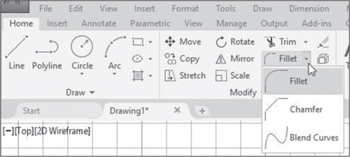
✓ Pick the Chamfer tool.
Notice that the Chamfer tool replaces the Fillet tool on the ribbon. AutoCAD prompts:
Select first line or [Undo Polyline Distance Angle Trim
mEthod Multiple]:
✓ Select Distance from the command line options.
The next prompt is:
Specify first chamfer distance <0.00>:
✓ Type 1 <Enter>.
AutoCAD asks for another distance:
Specify second chamfer distance <1.00>:
The first distance has become the default and will give you a chamfer cut evenly on both sides. If you want an asymmetrical chamfer, enter a different value for the second distance.
✓ Press <Enter> to accept the default, making the chamfer distances symmetrical.
At this point, you could proceed to chamfer each corner of the square independently. However, if you have drawn the square using the RECTANG command, you have a quicker option. The RECTANG command draws a polyline rectangle. Polylines are not discussed here, but for now it is useful to know that a polyline is a single entity comprising multiple lines and arcs. If you have drawn a closed polyline and specify the option in the CHAMFER or FILLET command, AutoCAD edits all corners of the object.
polyline: A two-dimensional object made of lines and arcs that may have varying widths.
✓ Select Polyline from the command line options.
AutoCAD prompts:
Select 2D polyline or [Distance Angle Method]:
✓ Run your cursor over any part of the red square.
You see a preview image of the square with chamfers at all four corners.
✓ Pick any part of the square.
You should have four even chamfers on your square, and your screen should resemble Figure 3-16.

Zooming and Panning with the Scroll Wheel
The capacity to zoom in and out of a drawing is one of the more impressive benefits of working on a CAD system. When drawings get complex, it often becomes necessary to work in detail on small portions of the drawing space. This is done easily with the ZOOM command or with the scroll wheel on your mouse. We begin with the convenient scroll wheel technique and then explore the ZOOM command in the next section.
✓ You should have a square with chamfered corners on your screen from the previous section.
Zooming and panning with the scroll wheel is simple and convenient, but less precise than some of the options in the ZOOM command. To better control results, position the crosshairs at or near the center of the objects you want to magnify, and do not move the crosshairs between zooms. AutoCAD will zoom in or out centered on the crosshairs’ position.
✓ Place the cursor near the center of the chamfered square and turn the scroll wheel forward (away from you) a small amount. If your scroll wheel moves in clicks, one click will do.
Your screen image will be enlarged.
✓ Turn the wheel forward again.
Your screen is further enlarged.
✓ Turn the wheel back (toward you) to zoom out.
Panning with the Scroll Wheel
Panning with the mouse is equally simple and does everything the PAN command will do. We notice that this technique does not work on every mouse, so we will also show you another way to pan. First, try this:
✓ Place the crosshairs anywhere inside or near the chamfered square.
✓ Press the scroll wheel down gently, so that it clicks, and hold it down.
As soon as you do this, the crosshairs will be replaced by the pan cursor, which looks like a small hand. With this cursor displayed, you can shift the position of your drawing within the drawing area.
✓ If you do not see the pan cursor, you can select it from the navigation bar on the side of the drawing area, as shown in Figure 3-17. Then move the cursor into the drawing area and hold down the pick button instead of the scroll wheel.

✓ With the pan cursor displayed, move the mouse slowly in several directions.
Objects in your drawing, including the screen grid and the X- and Y-axes, move with the motion of your mouse.
✓ Release the scroll wheel or the pick button.
✓ If necessary, press <Esc> to remove the pan cursor and return to the crosshairs.
The grid and objects drawn on it have moved, and the crosshairs replace the pan cursor.
Using the ZOOM Command
The ZOOM command has many options, a few of which we demonstrate here. Other options have more technical functions. Here we demonstrate zooming using the Extents, Window, Previous, and All options. These options are readily accessed from the navigation bar at the right of the screen.
Zoom |
|
|---|---|
Command |
Zoom |
Alias |
Z |
Menu |
View |
Tool |
|

Zoom Extents
Extents refers to the area within a drawing that actually contains complete drawn objects. When you Zoom to Extents, AutoCAD will display only that area of your drawing where you have actually drawn something. We demonstrate this first because it is the default option on the navigation bar. Because it may have been replaced by another option on your navigation bar, we start by opening the ZOOM command drop-down list.
✓ Pick the arrow below the Zoom tool on your navigation bar.
The Zoom tool is the third tool down on the navigation bar. This opens the drop-down tool list shown in Figure 3-18. Zoom Extents is at the top of the list.
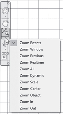
✓ Pick the Zoom Extents tool from the navigation bar, as shown in Figure 3-18.
AutoCAD immediately zooms to display an area containing the complete objects in your drawing.
Note
The extents area here is slightly larger than your chamfered square. This is because you have also drawn two lines and a circle on layers that are now turned off. Though these objects are not displayed, they are still part of your drawing and are considered when AutoCAD determines extents.
If your navigation bar has been turned off, you can turn it on by typing navbar <Enter> and then on <Enter>.
Zoom Window
A very common option for zooming is to create a window around the objects you want to magnify. You can select the Zoom Window tool from the drop-down list, but you can also force a window selection simply by entering the ZOOM command and drawing a window. Try this:
✓ Type z <Enter>.
This alias executes the ZOOM command. The prompt that follows looks like this:
[All Center Dynamic Extents Previous Scale Window Object]
<realtime>:
You can force a window selection by picking two points on the screen.
✓ Pick a point just below and to the left of the lower left-hand corner of your chamfered square (point 1 in Figure 3-19).
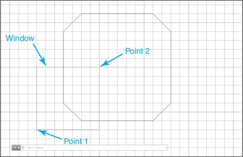
AutoCAD asks for another point:
Specify opposite corner:
You are being asked to define a window, just as in the ERASE command. This window is the basis for what AutoCAD displays next. Because you are not going to make a window that exactly conforms to the screen size and shape, AutoCAD interprets the window this way: Everything in the window will be shown, plus whatever additional area is needed to fill the screen. The center of the window becomes the center of the new display.
✓ Pick a second point near the center of your square (point 2 in the figure).
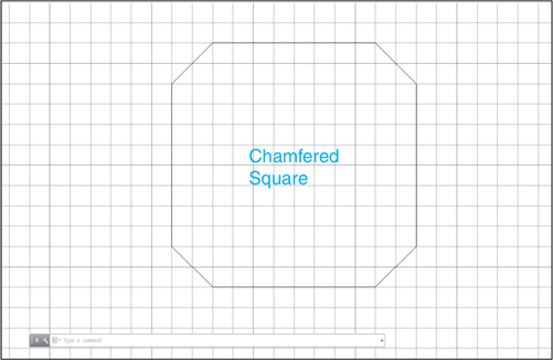
AutoCAD will zoom in dynamically until the lower left corner of the square is enlarged on your screen, as shown in Figure 3-20.

✓ Using the same method, try zooming up farther on the chamfered corner of the square. If Snap mode is on, you might need to turn it off.
Remember that you can repeat the ZOOM command by pressing <Enter> or the spacebar. At this point, most people cannot resist seeing how much magnification they can get by zooming repeatedly on the same corner or angle of a chamfer. Go ahead. After a couple of zooms, the angle does not appear to change, though the placement shifts as the center of your window changes. An angle is the same angle no matter how close you get to it, but what happens to the spacing of the grid and snap as you move in?
When you are through experimenting with window zooming, try zooming to the previous display, as follows.
Zoom Previous
✓ Press <Enter> to repeat the ZOOM command.
✓ Select Previous from the command line options.
You can also select Zoom Previous from the drop-down list on the navigation bar. You should now see your previous display.
✓ Zoom Previous as many times as you can until you get a message that says:
No previous view saved.
Zoom All
Zoom All zooms out to display the limits of the drawing, placing the origin (0,0) at the bottom of the drawing area. It is useful when you have been working in a number of small areas of a drawing and are ready to view the whole scene. It also quickly undoes the effects of zooming or panning repeatedly with the scroll wheel. We have used this option frequently when creating a new drawing.
To see it work, you should be zoomed in on a portion of your display before executing Zoom All.
✓ Use the scroll wheel or the ZOOM command to zoom in on a window within your drawing.
✓ Repeat ZOOM again.
✓ Select All from the command line options, or right-click and select All from the shortcut menu.
Entering Single-Line Text
AutoCAD has many options for drawing text. The simplest allows you to enter single lines of text and displays them as you type. You can backspace through lines to make corrections if you do not exit the command. We provide this brief introduction for those who may wish to label their drawings at this point.
For this exercise we add some simple left-justified text to your drawing. We stay on Layer 1 and add the words “Chamfered Square,” as shown in Figure 3-21.
✓ Open the Text drop-down list and then pick the Single Line text tool from the Annotation panel, as shown in Figure 3-22.

Note that this is the Annotation panel on the Home tab. There is also an Annotate tab on the ribbon that has more annotation options not explored here.
You see a prompt with three options in the command line:
Specify start point of text or [Justify Style]:
Here we use the default method by picking a start point. This gives us standard left-justified text, inserted left to right from the point we pick.
✓ Pick a start point near the middle left of the square, as shown in Figure 3-21. We chose the point (5,5).
Study the prompt that follows and be sure that you do not attempt to enter text yet:
Specify height <0.20>:
This gives you the opportunity to set the text height. The number you type specifies the height of uppercase letters in the units you have specified for the current drawing. We will specify a slightly larger text height.
✓ Type .3 <Enter>.
The prompt that follows allows you to place text in a rotated position:
Specify rotation angle of text <0>:
The default of 0° orients text in the usual horizontal manner. Other angles can be specified by typing a degree number relative to the polar coordinate system or by showing a point. If you show a point, it is taken as the second point of a baseline along which the text string will be placed. For now, we stick to horizontal text.
✓ Press <Enter> to accept the default angle (0).
Now it is time to enter the text itself. There is no prompt for text at the command line. Text is entered directly on the screen at the selected start point.
Notice that a blinking cursor has appeared at the start point on your screen. This shows where the first letter you type will be placed. Watch the screen as you type, and you can see dynamic text at work.
✓ Type Chamfered <Enter>.
Remember, you cannot use the spacebar in place of the <Enter> key when entering text. Notice that the text cursor jumps down a line when you press <Enter>.
✓ Type Square <Enter>.
The text cursor jumps down again. This is how AutoCAD allows for easy entry of multiple lines of text directly on the screen in a drawing. To exit the command, you need to press <Enter> again at the prompt.
✓ Press <Enter> to exit the command.
This completes the process and returns you to the command line prompt. Your screen should resemble Figure 3-21.
Chapter Summary
In this chapter you learned how to add layers, colors, linetypes, lineweights, linetype scales, fillets, and chamfers, so now you can create standard mechanical drawings that are more professional and contain more information about the objects represented. You can create layers with distinct qualities and uses to separate different types of information and control these layers independently. These layers can be turned on and off, frozen, thawed, locked, styled for plotting, or ignored in plotting. Additionally you can now zoom in or out of your drawing, pan across the area in which you are working, and add single-line text to your drawings.
Chapter Test Questions
Multiple Choice
Circle the correct answer.
1. Which linetype is loaded by default?
a. Solid
b. Center
c. Continuous
d. Diagonal
2. AutoCAD’s default color system is:
a. Pantone
b. Index
c. RGB
d. True Color
3. Which is not entered when you create single-line text?
a. Text height
b. Rotation angle
c. Text location
d. Text color
4. Which of these cannot be accomplished using the Layer drop-down list?
a. Create new layers
b. Set current layer
c. Turn layers on and off
d. Freeze and thaw
5. How many layers can you create in AutoCAD?
a. 255
b. As many as you like
c. 256
d. It depends on your computer
Matching
Write the number of the correct answer on the line.
|
|
True or False
Circle the correct answer.
1. True or False: You can zoom but not pan with the scroll wheel.
2. True or False: Objects on the same layer need not be the same color.
3. True or False: It is necessary to match layers and color numbers.
4. True or False: Linetypes need to be loaded, but colors do not.
5. True or False: You can draw in only one color on one layer.
Questions
1. What linetype is always available when you start a drawing from scratch in AutoCAD? What must you do to access other linetypes?
2. Name three ways to change the current layer.
3. You have been working in the Layer Properties Manager palette, and when you return to your drawing you find that some objects are no longer visible. What happened?
4. Describe the use of the scroll wheel for zooming.
5. In single-line text, what values must be specified before entering text content?
Drawing Problems
1. Make Layer 3 current and draw a green centerline cross with two perpendicular lines, each 2 units long and intersecting at their midpoints.
2. Make Layer 2 current and draw a hidden line circle centered at the intersection of the cross drawn in Step 1, with a diameter of 2 units.
3. Make Layer 1 current and draw a red square of 2 units on a side centered on the center of the circle. Its sides run tangent to the circle.
4. Use a window to zoom in on the objects drawn in Steps 1, 2, and 3.
5. Fillet each corner of the square with a 0.125 radius fillet.
Chapter Drawing Projects
 Drawing 3-1: Mounting Plate [BASIC]
This drawing gives you experience using centerlines, fillets, and chamfers. Because there are no hidden lines, you have no need for Layer 2, but we continue to use the same numbering system for consistency. Draw the continuous lines in red on Layer 1 and the centerlines in green on Layer 3.
Tip
Rather than start each drawing as a new drawing, use the Save Drawing As dialog box to save drawings under different names so that you don’t have to re-create layers in each new drawing.
Drawing Suggestions
GRID = 0.5
SNAP = 0.25
LTSCALE = 0.5
Change linetype scale along with setting grid and snap.
Pay attention to the linetypes as you draw, and change the current layer accordingly.
Draw the Mounting Plate outline with the LINE command. Then, chamfer the four corners and fillet all other corners as shown.

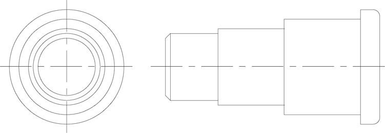
Drawing 3-2: Stepped Shaft [INTERMEDIATE]
This two-view drawing uses continuous lines, centerlines, chamfers, and fillets. You may want to zoom in to enlarge the drawing space you are actually working in, and pan right and left to work on the two views.
Drawing Suggestions
GRID = 0.25
SNAP = 0.125
LTSCALE = 0.5
Center the front view in the neighborhood of (2,5). The right-side view will have a starting point at about (5,4.12), before the chamfer cuts this corner off.
Draw the circles in the front view first, using the vertical dimensions from the side view for diameters. Save the inner circle until after you have drawn and chamfered the right-side view.
Draw a series of rectangles for the side view, lining them up with the circles of the front view. Then, chamfer two corners of the leftmost rectangle and fillet two corners of the rightmost rectangle.
Use the chamfer on the side view to line up the radius of the inner circle.
Remember to set the current layer to 3 before drawing the centerlines.
3D Models of Multiple-View Drawings
If you have any difficulty visualizing objects in the multiple-view drawings in this chapter, you may wish to refer to the images in Drawings 13-5A, B, C, and D. These are 3D solid models derived from 2D drawings.

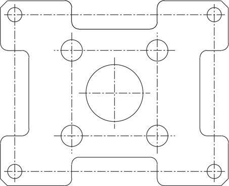
Drawing 3-3: Base Plate [INTERMEDIATE]
This drawing uses continuous lines, hidden lines, centerlines, and fillets. The side view should be quite easy once the front view is drawn. Remember to change layers when you want to change linetypes.
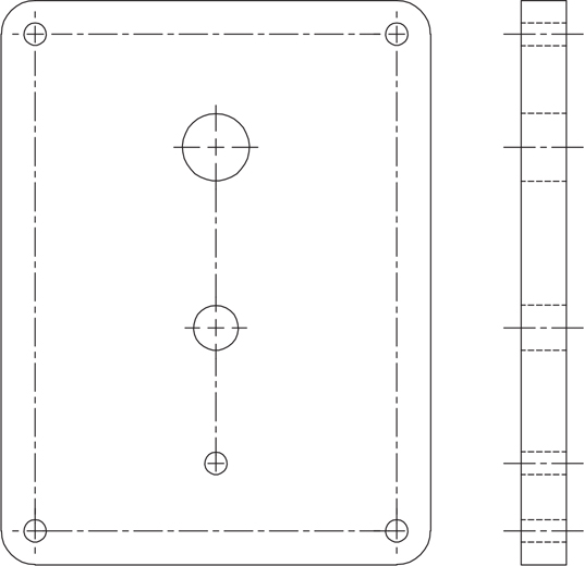
Drawing Suggestions
GRID = 0.25
SNAP = 0.125
LTSCALE = 0.5
Study the dimensions carefully and remember that every grid increment is 0.25, and snap points not on the grid are exactly halfway between grid points. The four circles at the corners are 0.38 (actually 0.375 rounded off) over and in from the corner points. This is three snap spaces (0.375 = 3 × 0.125).
Position the three circles along the centerline of the rectangle carefully. Notice that dimensions are given from the center of the screw holes at top and bottom.
Use the circle perimeters to line up the hidden lines on the side view, and the centers to line up the centerlines.

Drawing 3-4: Template [ADVANCED]
This drawing gives you practice with fillets, chamfers, layers, and zooming. Notice that because of the smaller dimensions here, we have recommended a smaller LTSCALE setting.
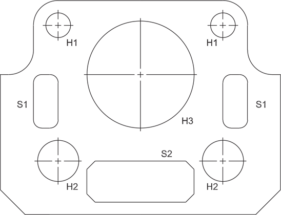
Drawing Suggestions
GRID = 0.25
SNAP = 0.125
LTSCALE = 0.25
Start by drawing the outline of the object and then fillet and chamfer as shown.
Because this drawing appears quite small on your screen, it would be a good idea to zoom in on the actual drawing space you are using and pan if necessary.
Typ is a standard abbreviation for typical and indicates that the dimension is used in multiple locations.
Draw the cutouts labeled S1 and S2 as rectangles and then fillet and chamfer as shown.
Label all cutouts as shown using the TEXT command.
Regen
When you change a linetype scale setting, you see the message Regenerating model in the command line. Regeneration is the process by which AutoCAD translates drawing data into screen images. Regeneration happens automatically when certain operations are performed.

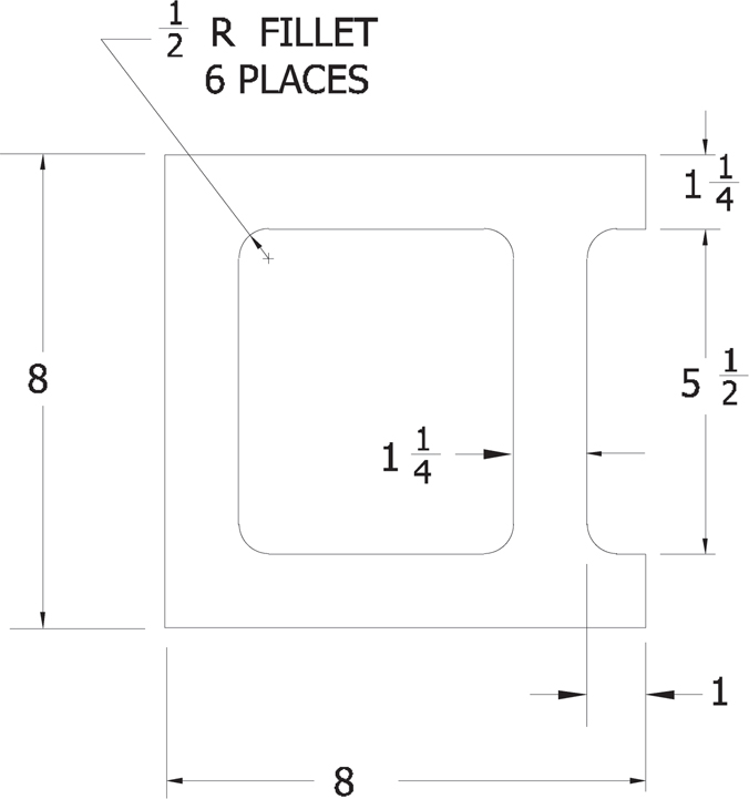
 Drawing 3-5: Half Block [INTERMEDIATE]
This cinder block is the first project using architectural units. Set units, grid, and snap as indicated, and everything falls into place nicely.
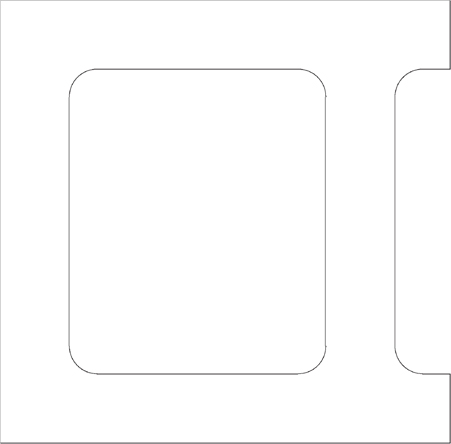
Drawing Suggestions
UNITS = Architectural; Precision = 0″-01/4″
GRID = 1/4″
SNAP = 1/4″
Start with the lower left corner of the block at the point (0″-01″, 0″-01″) to keep the drawing well placed on the display.
Set the fillet radius to 1/2″ or 0.5. Notice that you can use decimal versions of fractions. The advantage is that they are easier to type.
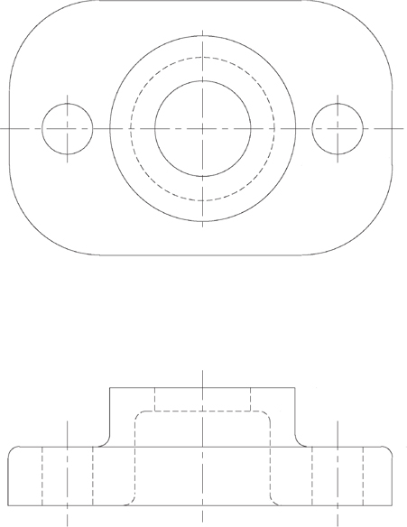
Drawing 3-6: Packing Flange [ADVANCED]
This drawing uses continuous lines, hidden lines, centerlines, and fillets. The side view should be quite easy once the top view is drawn. Remember to change layers when you want to change linetypes.
Drawing Suggestions
UNITS = Fractional
GRID = 1/4″
SNAP = 1/16″
LTSCALE = 0.5″
Study the dimensions carefully, and remember that every grid increment is 1/4″, and snap points not on the grid are exactly halfway between grid points. Notice that the units should be set to fractions.
Begin by drawing the outline and then the three centerlines in the top view. Then, proceed by drawing all circles.
The circles can be drawn using a center point and a diameter. Position the center of the circle where the centerlines cross, and type in the diameter.
Use the top view to line up all the lines on the side view.
