- Cover
- About This E-Book
- Title Page
- Copyright Page
- Preface
- Contents
- Part One: Basic Two-Dimensional Entities
- Chapter One: Lines and Essential Tools
- Chapter Two: Circles and Drawing Aids
- Introduction
- Changing the Grid Setting
- Changing the Snap Setting
- Changing Units
- Drawing Circles by Specifying a Center Point and a Radius
- Drawing Circles by Specifying a Center Point and a Diameter
- Accessing AutoCAD Online Help Features
- Using the ERASE Command
- Using Single-Point Object Snap
- Using the RECTANG Command
- Customizing Your Workspace
- Plotting or Printing a Drawing
- Chapter Summary
- Chapter Test Questions
- Chapter Drawing Projects
- Chapter Three: Layers, Colors, and Linetypes
- Introduction
- Creating New Layers
- Assigning Colors to Layers
- Assigning Linetypes
- Assigning Lineweights
- Changing the Current Layer
- Changing Linetype Scale
- Editing Corners Using FILLET
- Editing Corners Using CHAMFER
- Zooming and Panning with the Scroll Wheel
- Using the ZOOM Command
- Entering Single-Line Text
- Chapter Summary
- Chapter Test Questions
- Chapter Drawing Projects
- Chapter Four: Templates, Copies, and Arrays
- Chapter Five: Arcs and Polar Arrays
- Chapter Six: Object Snap
- Introduction
- Selecting Points with Object Snap (Single-Point Override)
- Selecting Points with Running Object Snap
- Object Snap Tracking
- Using the OFFSET Command (Creating Parallel Objects with OFFSET)
- Shortening Objects with the TRIM Command
- Extending Objects with the EXTEND Command
- Using STRETCH to Alter Objects Connected to Other Objects
- Creating Plot Layouts
- Chapter Summary
- Chapter Test Questions
- Chapter Drawing Projects
- Part Two: Text, Dimensions, and Other Complex Entities
- Chapter Seven: Text
- Introduction
- Entering Single-Line Text with Justification Options
- Entering Text on an Angle and Text Using Character Codes
- Entering Multiline Text Using MTEXT
- Editing Text in Place with TEXTEDIT
- Modifying Text with the Quick Properties Palette
- Using the SPELL Command
- Changing Fonts and Styles
- Changing Properties with MATCHPROP
- Scaling Previously Drawn Entities
- Creating Tables and Fields
- Using AutoCAD Templates, Borders, and Title Blocks
- Chapter Summary
- Chapter Test Questions
- Chapter Drawing Projects
- Chapter Eight: Dimensions
- Introduction
- Creating and Saving a Dimension Style
- Drawing Linear Dimensions
- Drawing Multiple Linear Dimensions Using QDIM
- Drawing Ordinate Dimensions
- Drawing Angular Dimensions
- Dimensioning Arcs and Circles
- Dimensioning with Multileaders
- Changing Dimension Text
- Using Associative Dimensions
- Using the HATCH Command
- Scaling Dimensions Between Paper Space and Model Space
- Chapter Summary
- Chapter Test Questions
- Chapter Drawing Projects
- Chapter Nine: Polylines
- Introduction
- Drawing Polygons
- Drawing Donuts
- Using the FILL Command
- Drawing Straight Polyline Segments
- Drawing Polyline Arc Segments
- Editing Polylines with PEDIT
- Drawing Splines
- Creating Path Arrays
- Drawing Revision Clouds
- Drawing Points
- Using Constraint Parameters
- Using AutoConstrain and Inferred Constraints
- Chapter Summary
- Chapter Test Questions
- Chapter Drawing Projects
- Chapter Ten: Blocks, Attributes, and External References
- Introduction
- Creating Groups
- Creating Blocks
- Inserting Blocks into the Current Drawing
- Creating Dynamic Blocks
- Adding Constraints to Dynamic Blocks
- Accessing Data in a Block Table
- Using the Windows Clipboard
- Inserting Blocks and External References into Other Drawings
- Using the AutoCAD DesignCenter
- Defining Attributes
- Working with External References
- Extracting Data from Attributes
- Creating Tool Palettes
- Exploding Blocks
- Chapter Summary
- Chapter Test Questions
- Chapter Drawing Projects
- Chapter Seven: Text
- Part Three: Isometric Drawing and Three-Dimensional Modeling
- Chapter Eleven: Isometric Drawing
- Introduction
- Using Isometric Snap
- Switching Isometric Planes
- Using COPY and Other Edit Commands
- Drawing Isometric Circles with ELLIPSE
- Drawing Text Aligned with Isometric Planes
- Drawing Ellipses in Orthographic Views
- Saving and Restoring Displays with VIEW
- Chapter Summary
- Chapter Test Questions
- Chapter Drawing Projects
- Chapter Twelve: 3D Modeling
- Introduction
- Creating and Viewing a 3D Wireframe Box
- Defining User Coordinate Systems
- Exploring the 3D Basics Workspace
- Creating Solid Boxes and Wedges
- Accessing Different Visual Styles
- Creating the Union of Two Solids
- Working with DUCS
- Creating Composite Solids with SUBTRACT
- Creating Chamfers and Fillets on Solid Objects
- Practicing 3D Gizmo Editing
- Rendering Solid Models
- Changing Viewpoints with the ViewCube
- Creating Layouts with Multiple Views
- Chapter Summary
- Chapter Test Questions
- Chapter Drawing Projects
- Chapter Thirteen: More Modeling Techniques and Commands
- Introduction
- Drawing Polysolids
- Drawing Cones
- Drawing Pyramids
- Drawing Torus
- Slicing and Sectioning Solids
- Mesh Modeling
- Adjusting Viewpoints with 3DORBIT
- Creating 3D Solids from 2D Outlines
- Walking Through a 3D Landscape
- Creating an Animated Walk-Through
- Chapter Summary
- Chapter Test Questions
- Chapter Drawing Projects
- Chapter Eleven: Isometric Drawing
- Appendix A: Drawing Projects
- Appendix B: Creating Customized Panels
- Appendix C: Menus, Macros, and the CUI Dialog Box
- Index
- Appendix D: Additional Tools for Collaboration (Online)
- Glossary (Online)
- Code Snippets
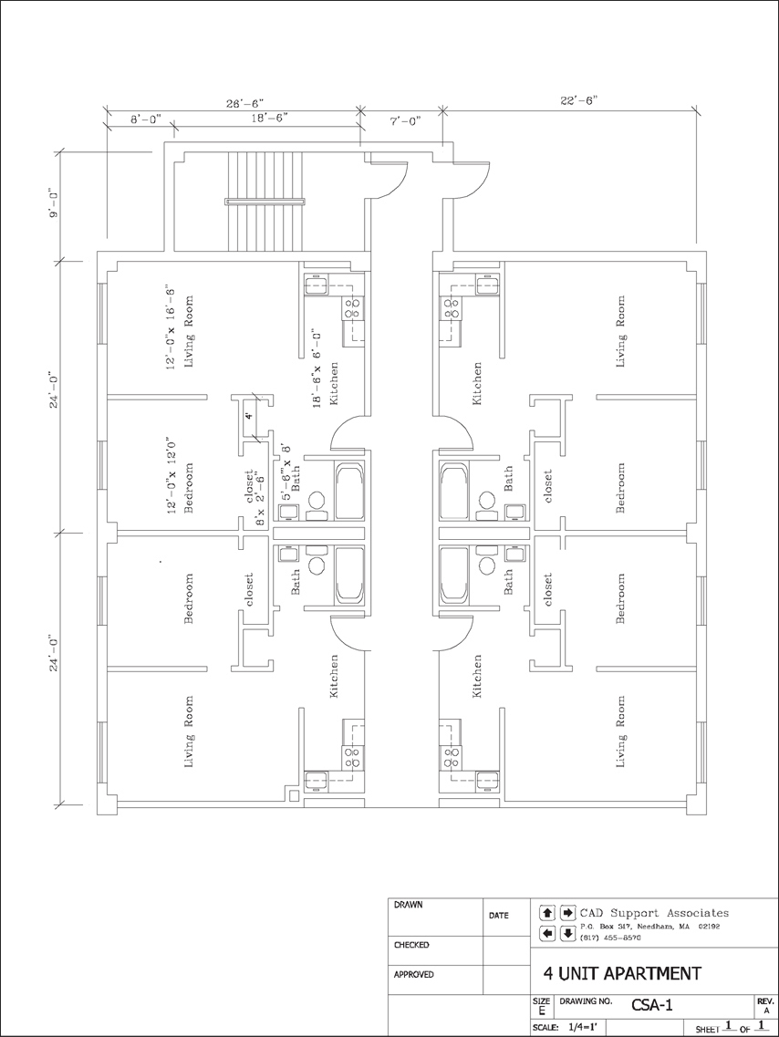
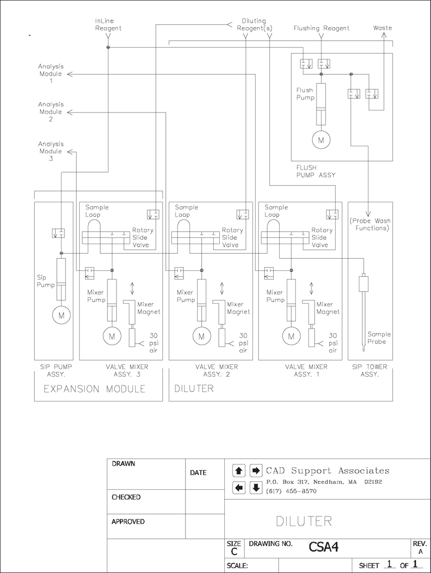
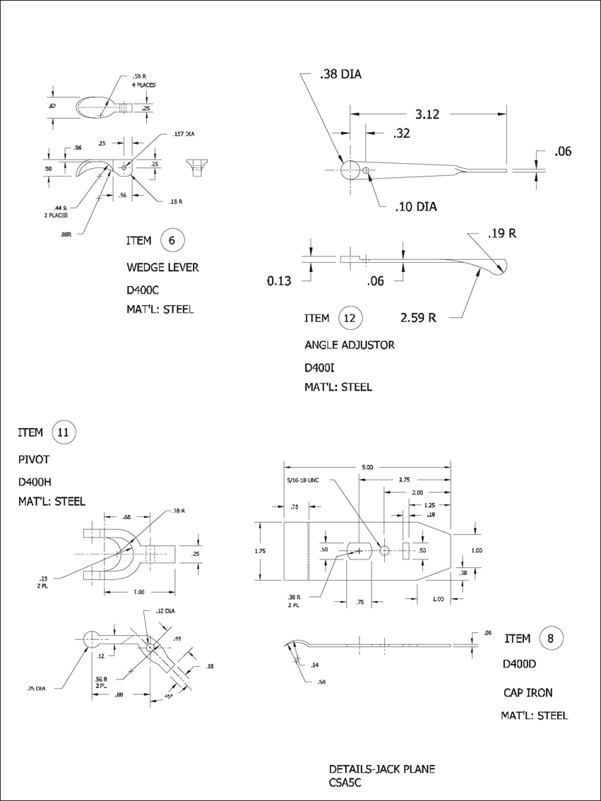
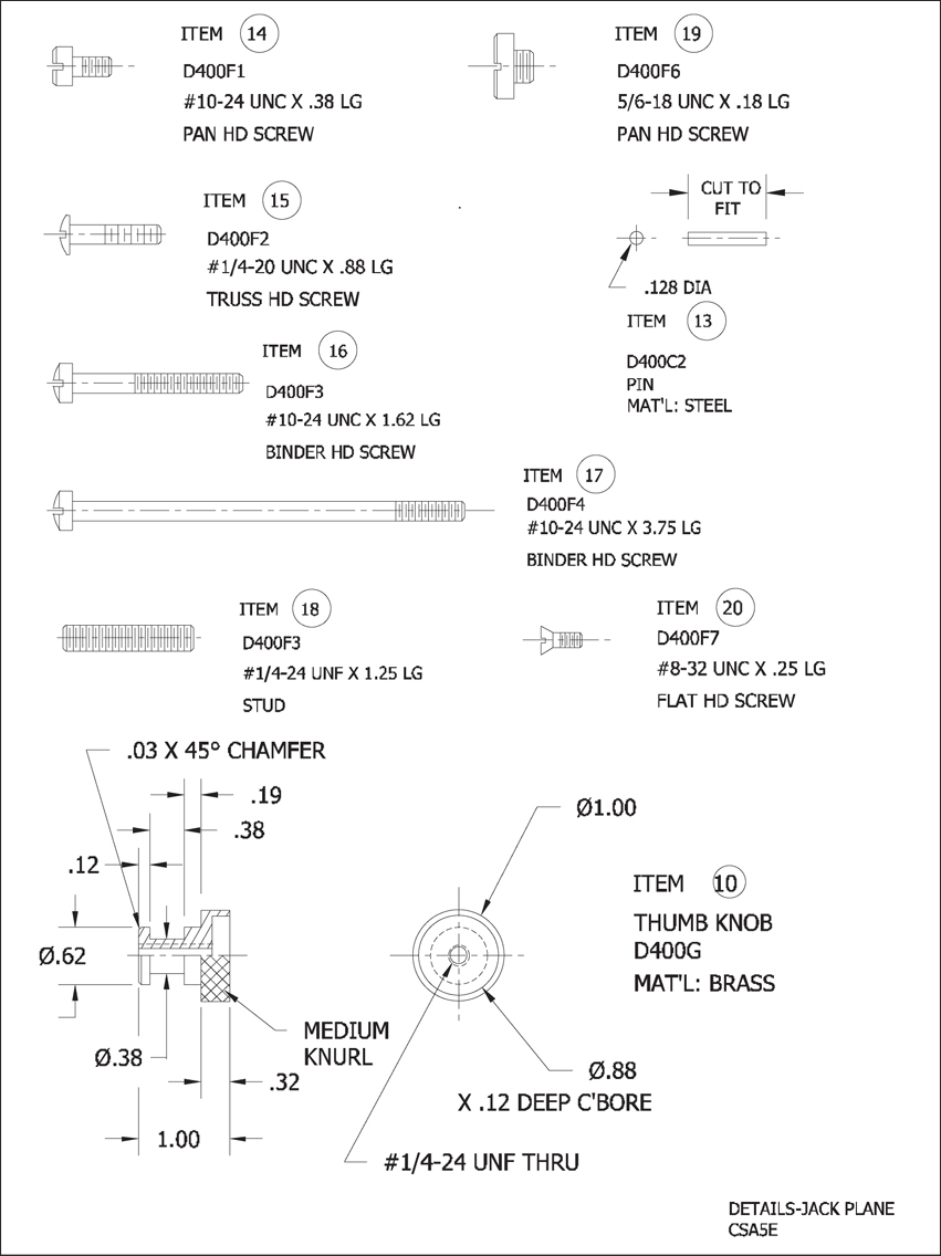
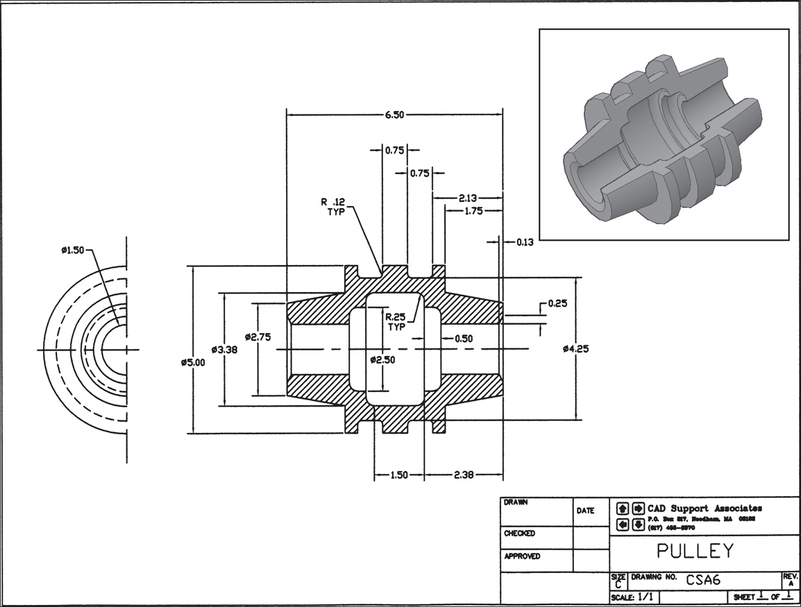
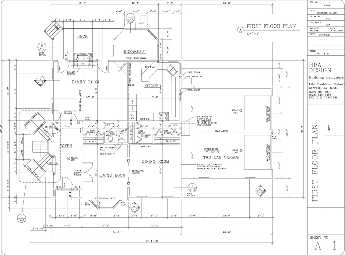
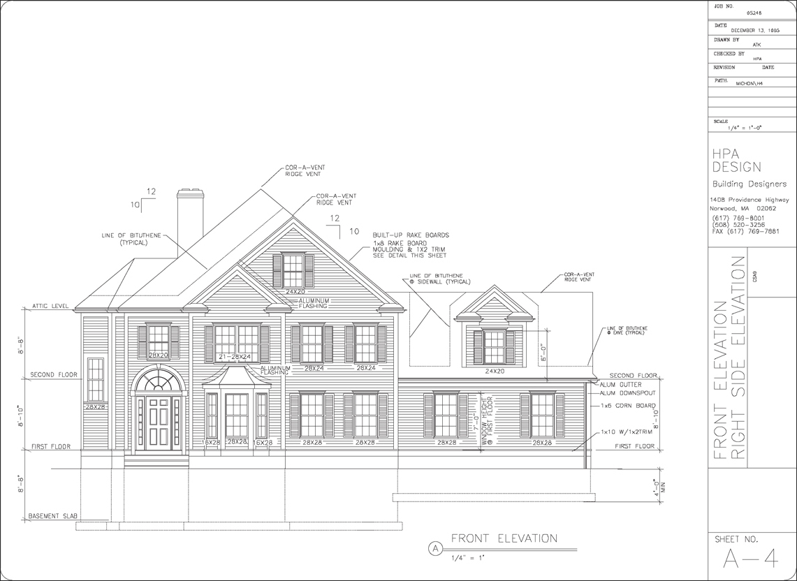
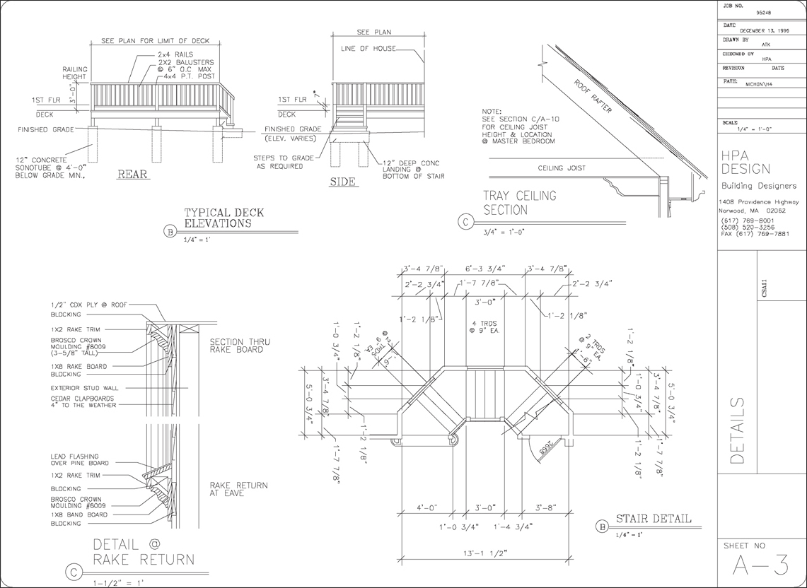
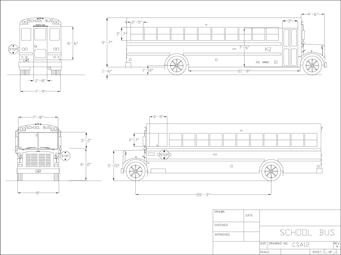
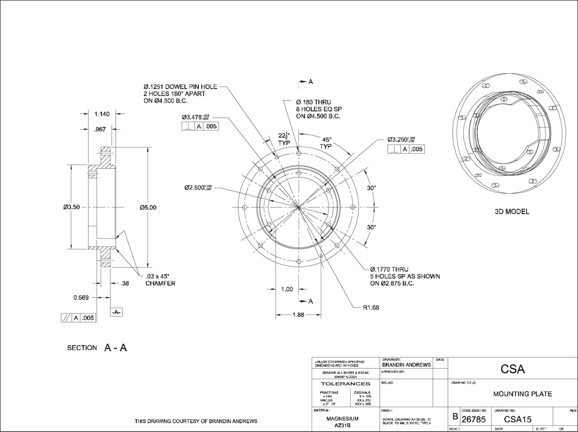
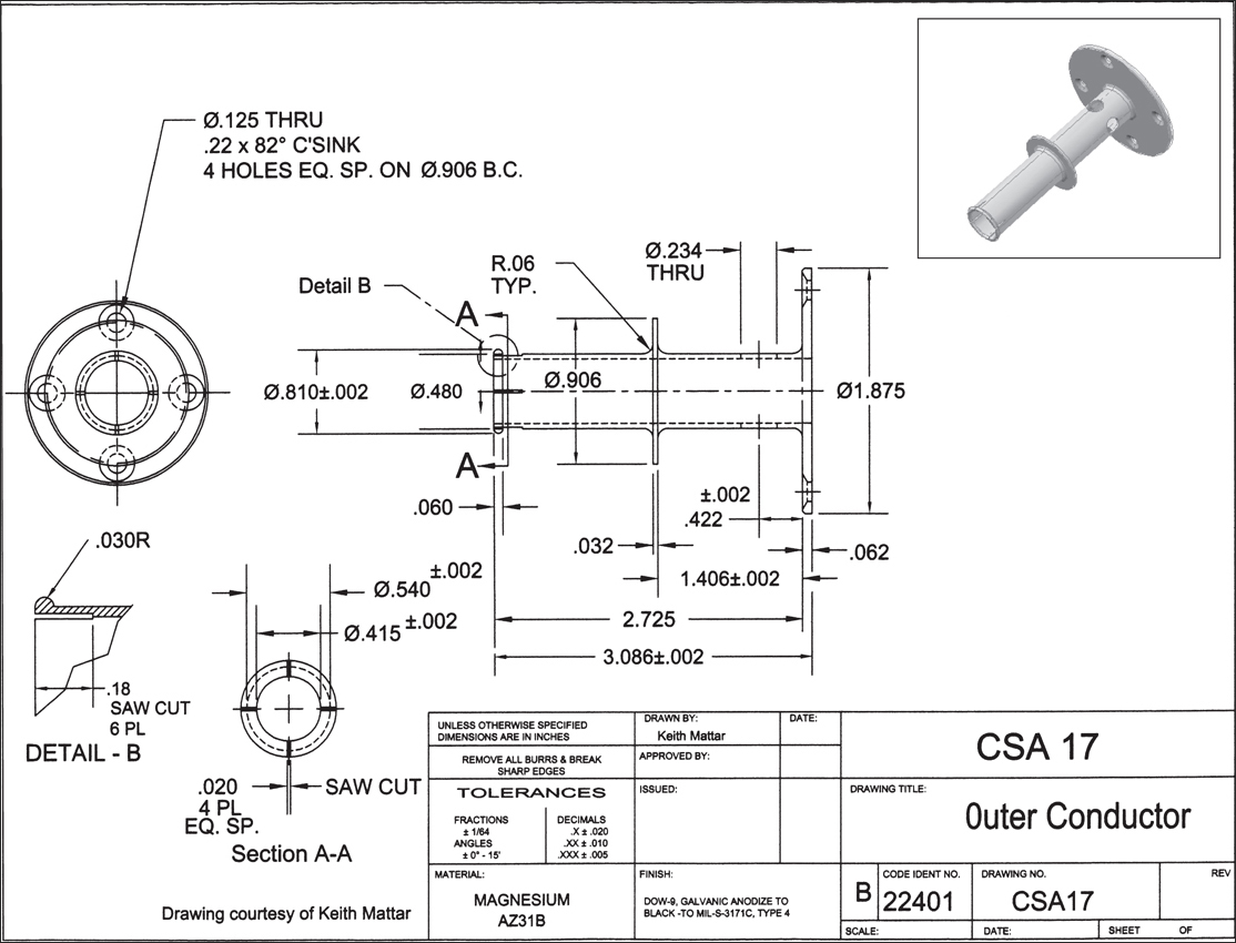
Appendix A: Drawing Projects
The drawings on the following pages are offered as additional challenges and are presented without suggestions. They may be drawn in two or three dimensions and may be presented as multiple-view drawings, hidden-line drawings, or rendered drawings. In short, you are on your own to explore and master everything you have learned.


-
No Comment
..................Content has been hidden....................
You can't read the all page of ebook, please click here login for view all page.