
Appendix D: Additional Tools for Collaboration
In addition to the programming and customizing tools that are used by a single user at a computer workstation, there are numerous tools that are encountered only in collaborative environments, where the workspace extends beyond the individual and the individual computer. In this appendix, we introduce an array of these tools, so that readers may enter a collaborative environment with a roadmap to these processes. The tools presented here are not necessary for the completion of any independent drawing, but they quickly become necessary as you begin to share your work with others.
Block libraries and external references are two very powerful collaboration tools you have already encountered. You can create useful blocks, external references, and libraries of content within your own drawings, but the real power appears when you can reach across many platforms beyond what is on your computer to borrow and generate sharable content. As we have seen, the AutoCAD DesignCenter organizes these processes into a single interface. Gaining access to content outside of your own hard drive requires Internet or local network connectivity and at least one of several applications that facilitate sharing and collaborating online.
In this appendix, we present a basic hierarchy of these applications and end with some important considerations about CAD Standards that apply when accessing data from files created elsewhere.
Internet Features
Getting the most out of all collaborative processes relies heavily on Internet connectivity and cloud-based applications. With a few simple tools, AutoCAD drawings can be published to the Web, transferred as email attachments, uploaded, downloaded, and included as part of websites and home pages. CAD professionals working on projects together can edit and comment on versions of the same drawing, using cloud-based drawing, editing, and markup features. While access to these platforms can proceed directly from the AutoCAD drawing space, the apps involved are completely separate from AutoCAD. Most require that you have an Autodesk account.
The following sections describe a few basic tools for interacting with the cloud and the Internet through the AutoCAD platform.
BROWSER Command
The first level in the hierarchy of online features are the commands that simply allow you to access Internet content directly from within AutoCAD. AutoCAD is a fully integrated Internet program, so if you have Internet access, you can access websites directly from the AutoCAD drawing space. You first must be connected to your Internet service provider. Once connected, you can move easily in and out of AutoCAD as you access all the resources available on the Web.
The following steps demonstrate how to access Autodesk.com and other websites from within the AutoCAD software.
✓ First, you must be sure that you are connected to an Internet service provider.
You may already be connected to the Internet, depending on your system. If you are not, you need to go through a log-in procedure. In most cases, AutoCAD automatically initiates your log-in procedure when you enter a Web command. If this does not happen, do not exit AutoCAD, but use the Minimize button (the third button from the right at the top of the screen, with the minus sign) to temporarily leave the AutoCAD drawing window. We cannot give you specific instructions for connecting to the Internet from your system. For these, consult your Internet software documentation, instructor, or system manager.
✓ If necessary, after connecting to the Internet, click the AutoCAD icon on the Windows taskbar to return to the AutoCAD drawing window.
✓ At the command line prompt, type browser <Enter>.
This is the BROWSER command, through which you can access Internet addresses, local network addresses, or locations on your own computer. AutoCAD prompts for an address:
[Enter Web location (URL)] <http:www.autodesk.com>:
The default location is shown within the arrows (< >) and may be different from the one shown here. It can be any valid location on your computer or on the Internet. Pressing <Enter> at this prompt takes you directly to this website. It will open in a new window, leaving the AutoCAD application window open in the background.
Note
All descriptions and illustrations of Web pages were current as of the writing of this text. Websites can and should change; so by the time you read this, things may look different.
✓ Press <Enter> to accept the default website.
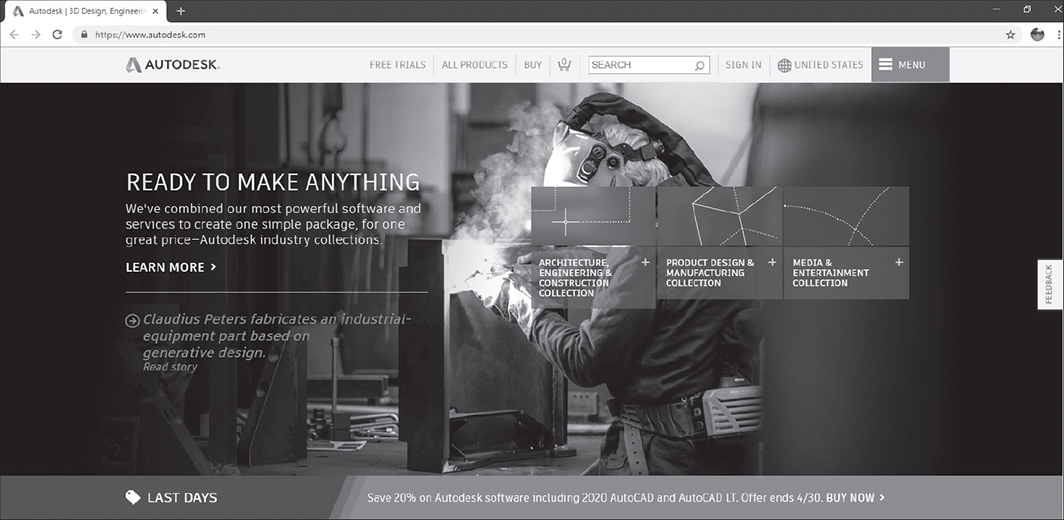
Wait. . . . If your Internet connection is in order, you will see the Autodesk website home page, as shown in Figure D-1, or whatever website is the default location on your system. While you’re here, take a minute to look around, then close the Autodesk website and return to the AutoCAD application window.
INETLOCATION Command
INETLOCATION allows you to change the default Uniform Resource Locator (URL) used in the BROWSER command. If you visit the same website repeatedly, you can save time and effort by making that your default web address in the BROWSER command. The procedure is as follows.
✓ Type Inetlocation <Enter>.
AutoCAD will prompt for a new location. Once entered, the specified location will become the new default for the BROWSER command. Note that the command requires a complete web address, beginning “http:www.”
✓ Enter your preferred Internet location.
✓ Type Browser <Enter>.
The Web address you have specified will open in a new window whenever you enter BROWSER without typing in a new Web address.
Your Autodesk Account
You will not get very far in the world of Autodesk online services without opening an Autodesk account. Signing up for an account is free. Although there are many steps, the process will be familiar to anyone who has experienced signing up for an online account of any kind. It requires an email address and a password. Once established, your account provides access to cloud-based Internet resources that are not otherwise available. The following steps will set you up with a free account.
✓ Click the Sign In button on the title bar, as shown in Figure D-2.

This opens the short list of options shown in the figure.
✓ Click the Sign In option, as shown.
You see a Sign In dialog box with a Create Account option. Once you have an account, you can enter your email address and your password here to access your Autodesk account.
✓ Click Create Account.
This brings you to the Create account dialog box shown in Figure D-3.
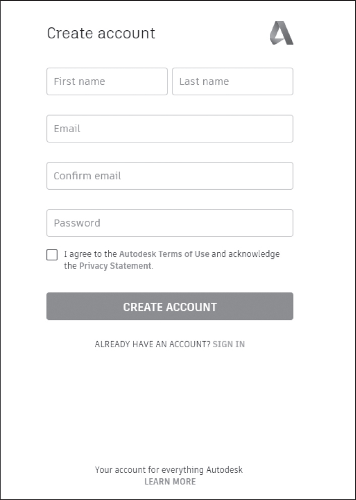
✓ Enter your name.
✓ Enter your email address twice, as required.
✓ Create and enter a password that meets the required qualities (at least 1 letter, at least 1 number, at least 8 characters, at least 3 distinct characters).
✓ Click Create Account again.
✓ Click the box to agree to the Autodesk Terms of Use.
✓ Click Create Account once more.
You see a message box stating that your account has been created and stating, “This single account gives you access to all your Autodesk products.”
✓ Scroll down and click Done.
You will now be offered the opportunity to protect your account with 2-step verification if you want. Or, you can choose to add this later. Once you have completed this step, or chosen to be reminded later, you will return to your AutoCAD drawing window. Your account user name will now replace the “Sign in” button on the title bar.
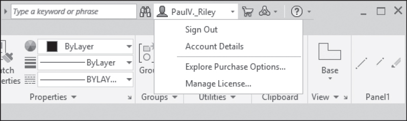
✓ Click your account name on the title bar.
This opens a list of four options shown in Figure D-4: Sign Out, Account Details, Explore Purchase Options, Manage License.
A360, Fusion 360, and BIM 360
Once you have an Autodesk account, you have options that are available to you through Autodesk.com. These include a wide variety of Autodesk products designed to address the specialized needs of particular industries and processes within industries. With the exception of A360, all these Autodesk products require paid subscriptions. Here we proceed by accessing the Autodesk products page and introducing three common Autodesk cloud-based platforms.
✓ From the list of options shown in Figure D-4, select Explore Purchase Options.
This opens a product page with the search box shown in Figure D-5.
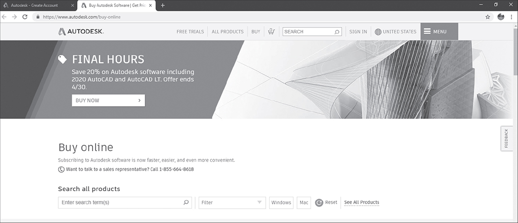
✓ In the Search All Products edit box, type 360 <Enter>.
All three of the platforms we are introducing have “360” in their names, so this search will connect you to all of them. If you scroll down a little, you will see Fusion 360 listed as a best seller. On the next line below, you see BIM 360 on the left and A360 on the right. You can get more information on any of them by clicking the + SEE MORE button below the name of the product.
Detailed information on the capabilities of these and other Autodesk products are readily available from Autodesk. It is not our intent to duplicate this information, but to facilitate students’ ability to move beyond desktop AutoCAD into related cloud-based services and online collaboration. Briefly, A360, like the SHAREVIEW command in the following section, is intended for 1:1 file sharing, commenting, and review. It is also intended as a single project sharing space. The free A360 account has a 5-gigabyte limit on server space. From your A360 account home page you can upload files and create links to share with others, much as you can with SHAREVIEW. Unlike SHAREVIEW links, A360 links do not need to be extended after 30 days. The originator of a shared view or A360 file automatically becomes the administrator of that file and related files shared through the same account.
BIM 360 and Fusion 360 are more complex and feature rich. They are designed for teamwork and collaboration. They have more organizational features to facilitate file management and collaboration, as well as more markup and editing capacity. Projects developed on these platforms require a designated administrator and allow any member of a project team to upload, view, comment, and mark up files related to the project. BIM (Building Information Modeling) 360 is Autodesk’s online platform for architectural project management. Fusion 360 is the design and manufacturing platform.
SHAREVIEW Command
BROWSER and INETLOCATION give you access to Web locations. But collaboration with other designers most often requires the ability to share and comment on drawing files. Once you have a free Autodesk account, the SHAREVIEW command is a simple method of sharing files. Using SHAREVIEW you can send a link to anyone who has Internet access. The link will be good for 30 days only, but can be extended by you. The receiving party does not have to have an Autodesk account or any Autodesk product to view the linked file. The features are limited, however. Without an Autodesk account, the person(s) receiving the shared file can only view the file. In order to add comments to the file they must also have a free Autodesk account, but do not need any Autodesk product or subscription. To share files, however, you as the originator must have an Autodesk account along with your AutoCAD software.
Following are the steps for creating a file sharing link, assuming you are signed in to an Autodesk account.
✓ From within a drawing that you want to share, select Application menu > Publish > Share View.
This executes the SHAREVIEW command. You will be presented with a dialog box similar to Figure D-6. There are options for sharing (or not sharing) the current view, 2D views only, model views, layouts, and object properties.
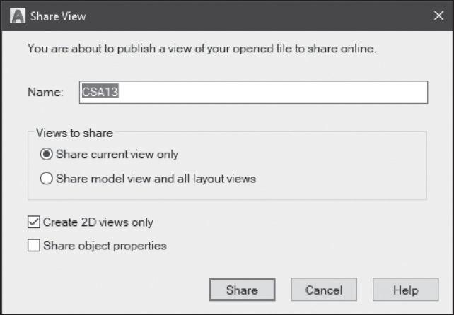
✓ Select the options you want and type a name for the linked file in the Name box.
Notice that the name of the shared view does not need to match the name of the drawing.
✓ Click Share.
You see a message that says, “Background processing of the shared view is ready to start,” as shown in Figure D-7.
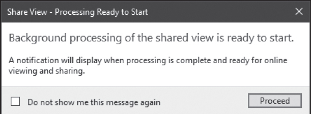
✓ Click Proceed.
When the shared view has been uploaded, you will see a notification in the lower right corner of your drawing window indicating that the view upload is complete. You can now access the view in the cloud and send the viewing link to others.
✓ Click View in Browser on the notification.
The shared view will open in a new window. This is the Autodesk Viewer window.
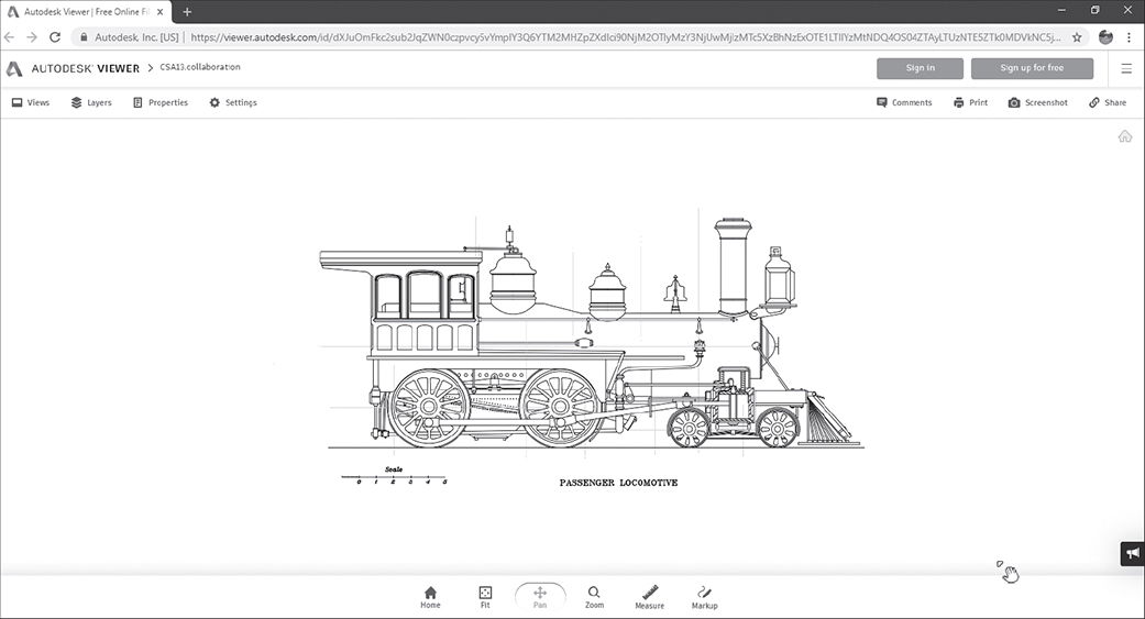
Autodesk Viewer
The Autodesk Viewer is a viewing space used by many Autodesk online applications. It is the space where shared files will appear after they have been uploaded. You can reach the window by clicking View in Browser on the notification in an open AutoCAD application window after sharing a file. You can also enter the viewer directly by searching for Autodesk Viewer in your browser and then answering the prompt to open your Autodesk account.
Across the top of the viewer window are the options shown in Figure D-8. On the left are options for viewing separate layers, views, and properties. The accessibility of these options depends on how the file has been shared by the originator (you). On the right are the options for adding comments, printing the image, taking a screenshot of the image, and, most important, the Share button. With the exception of Share, these options are available to anyone with an Autodesk account and the file link you send them. Share is only available to the originator of the file, who is automatically the administrator of all pages related to this file. Share is the option we are most interested in at this point. The whole purpose of uploading a file to the viewer is to be able to share it.
The steps to share a file, once you have it uploaded to the Viewer, are as follows.
✓ Click the Share button at the far right.
Once again you will be asked to sign up or sign in to your Autodesk account.
✓ Click the Sign in button.
✓ Enter the email address associated with your Autodesk account and click Next.
✓ Enter your password and click Sign in.
A Share message box will open on the right side of the screen with the sharing link in the middle, as shown in Figure D-9. You can highlight and copy this link, or simply click on the Copy button below the link. Either way, the link will be stored temporarily on your clipboard and can be copied into an email, text message, or other sharable document.
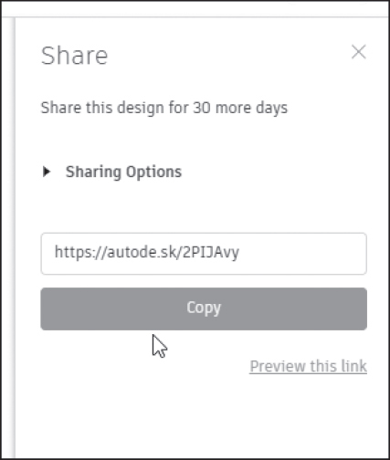
✓ Click the Copy button.
✓ Leave the Autodesk Viewer window and open your email or text program.
✓ Paste the link into an email or text message
✓ Send the email or text to collaborators, co-workers, clients, or potential clients.
Anyone receiving the link can then open the link in the Autodesk viewer.
CAD Standards
The sharing of drawing files and creation of work projects accessed by users in different locations and companies creates the need for ways to manage variations in drawing standards. The CAD Standards feature in AutoCAD is important in work environments where drawings from one organization may be used in other organizations or departments. Using CAD Standards files allows quick checking and modifying of drawings to ensure that externally created or outsourced drawings use standards compatible with standards in place for drawings created in-house.
AutoCAD’s CAD Standards feature requires the use of a drawing standards file. This can be any drawing that uses the desired standards, including layer definitions and properties, dimension styles, text styles, and linetypes. To understand the issues involved, imagine that in Your Company, Inc. all drawings have a standard layer (we’ll call it Layer1) that is red. To support this practice, a certain Drawing A has been defined as a CAD Standards file (saved with a .dws extension). Your Company receives Drawing B from Their Company. Drawing B and Drawing A both have a layer called Layer1, but in Their Company, Layer1 is yellow. As Your Company’s CAD expert, you must ensure that Drawing B complies with Your Company’s standards. You proceed as follows:
✓ Open Drawing B from Their Company.
✓ Select the Manage tab > CAD Standards panel > Configure tool from the ribbon.
This opens the Configure Standards dialog box.
✓ Click the <+> button to add a Standards file.
✓ From the Select Standards file dialog box, select Drawing A.dws as the CAD Standards file.
✓ In the Configure Standards dialog box, click the Check Standards button.
This opens a dialog box that shows you any discrepancies between Drawing A.dws and Drawing B.
✓ Pick the Fix button to alter Layer1 in Drawing B to match the standard of Drawing A.
Now that Drawing A is defined as a Standards file for Drawing B, whenever you try to change a property in Drawing B and it does not match a standard, you will get a Standards Violation notification in the lower right corner of your screen. You can use the blue link to run a standards check and fix the problem, or you can ignore and close the message.
Layer Translation
Layer translation is closely related to CAD Standards checking. It works similarly but addresses only layers and allows you to adjust the layers in any drawing to match layers in another drawing. You are not restricted to using drawings that have been defined as Standards files but can use any drawing to shape any other drawing. Properties that can be matched are all the properties that define layers. To translate Layer1 properties in Drawing A to Layer1 properties in Drawing B, do the following:
✓ Open Drawing B.
✓ Select the Manage tab > CAD Standards panel > Layer Translator tool from the ribbon.
This opens the Layer Translator . Layers in the current drawing are shown in the Translate From panel. There is nothing in the Translate To panel until we load a drawing.
✓ Click Load.
This opens a Select Drawing File dialog box. You can select a drawing, a template drawing, or a CAD Standards drawing file.
✓ Navigate to the folder where Drawing A is located.
✓ Select Drawing A.
Notice that this can be any drawing. It does not have to be a .dws drawing.
✓ Click Open.
Layers from Drawing A are now listed in the Translate To panel.
✓ Highlight Layer1 in both panels.
✓ Click Map.
The proposed translation shows in the Layer Translations Mapping panel.
✓ Click Translate.
✓ Click Yes to save or No to eliminate the old layer information in Drawing B.
Management of Named Objects
When managing multiple drawings from different sources, you are likely to encounter the problem of duplicate definitions. For example, what happens when a drawing that is externally referenced or block-inserted has layers, linetypes, text styles, dimension styles, blocks, or views with names that are the same as those in the current drawing? Good question. In the case of block drawings, name definitions in the current drawing override those in the inserted block, regardless of its origin. In the case of Xrefed drawings, named objects are given special designations that eliminate the duplication. For example, if Drawing B is attached to Drawing A and both have a layer called FLOOR, a new layer called B|FLOOR is created in A.
Sheet Set Management
Most industrial design projects involve not one drawing but a set of drawings detailing different views or different aspects of a single design. When a design project is to be communicated to a client or a consultant, it is likely to be represented by a whole set of related drawings. Sets of drawings like these, called sheet sets, may be created manually by saving particular layouts from individual drawings and then assembling all the relevant layouts and views in a single location. This process can become quite complex, especially when the individual drawings are on different computers and rely on external references, font files, plot files, and so on that may reside in different locations. To facilitate the creation of sheet sets, AutoCAD includes a system called the Sheet Set Manager. Through this interface, layouts from individual drawings are collected into a new drawing. Here, layouts can easily be organized into categories and subsets so that the sheet set presents a coherent design concept. One sheet of the set may be designated as the title sheet, and this may display a table showing the organizational hierarchy of the complete sheet set. Sheets in the sheet set are given numbers and designations shown in standard symbol blocks that update automatically if the number and organization of the sheet set changes. Consider the following workflow:
✓ Create drawings in model space.
✓ In each drawing, create layouts with a design presentation image.
✓ Using the Sheet Set Manager, collect layouts from all relevant drawings into a single set.
✓ Create a title sheet listing all layouts (sheets) and showing how they are organized.
✓ Create a sheet set package that contains the sheet set and all files required to view the set, all organized through the Sheet Set Manager.
✓ Archive the sheet set.
✓ eTransmit the sheet set to a client or consultant.