All of the profiles listed in Table 6-1 are based upon the The Serial Port Profile. Potentially it will impact upon new profile development; in one way or another, you will find yourself returning to it on a regular basis.
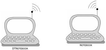
With its firm foundation in all the profiles illustrated in Table 6-1, it is clear that a sound knowledge of the Serial Port Profile is one of the key prerequisites of current profile development. Its purpose is to provide a set of protocols and procedures which in turn, allows RFCOMM to provide serial port emulation for Bluetooth-enabled devices. The scenario provided for this profile, as shown in Figure 6-1, illustrates two devices communicating over an emulated serial communications link. The scenario depicted purports legacy application support, providing a transparent wireless transport.
This section considers existing usage models through scenarios that are typical for the Serial Port Profile. We begin by exploring the existing model where, at face value, the Serial Port Profile provides the ability to impart serial port emulation as part of its application services. Predominately, at the user interface level, the user is notified of an available service which in turn, can be used as a means of data transport. In Figure 6-2, we illustrate the availability of a Bluetooth serial port being made available to the user.
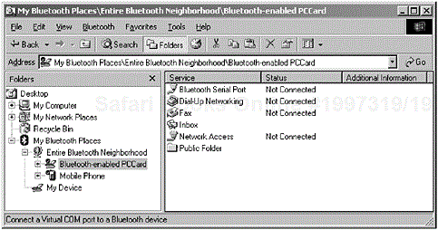
Figure 6-2. The availability of a Bluetooth serial port is made available, where legacy applications can make use of the services it provides. (Courtesy of TDK Systems Europe.)
Table 6-1. The list of profiles that are built upon the Serial Port Profile.
|
PROFILE |
CHAPTER |
|---|---|
|
Headset |
7 |
|
Dial-up Networking |
8 |
|
Fax |
9 |
|
LAN Access |
10 |
|
Generic Object Exchange |
11 |
|
Hands-free |
17 |
|
Phone Access |
17 |
|
SIM Access |
17 |
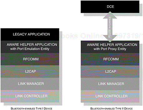
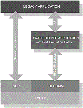
It is important to note that the roles presented by this profile are not restricted to the typical master-slave construction, although DeviceA is depicted as the initiator and DeviceB as the acceptor. Figure 6-3 provides the components that make up the Bluetooth protocol stack and shows where the interface is exposed for legacy, cable replacement and intermediate applications; these are all discussed in more detail later. As a further clarification, Figure 6-3 shows the availability of an interface at the RFCOMM level [1] and illustrates how each type of application would employ its use; developers have a choice as to how they choose to use such an interface and what information to exchange. As such, the RFCOMM protocol itself does not distinguish between types of devices, that is Type I and Type II.
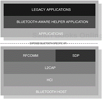
Figure 6-3. From a development perspective, the exposure of the API enables the provision of legacy, cable replacement and intermediate application support. It also shows where a Bluetooth aware helper application would reside.
Before continuing further, it is important from a development point of view to reacquaint ourselves with both the definition of an application and the types of devices. The profile offers some explanation of both legacy and Bluetooth aware helper applications, but it is also important when reading this to draw upon our own prior knowledge and experience. This will allow us to fully understand the perspective of the applications from both the developer and the user’s point of view.
The following sections have broken the term application down into four categories to help us understand the various usage models available and how serial port emulation is provided.
There are numerous applications [2] readily available that are capable of data transfer through the standard serial communications port. This is primarily achieved by configuring the legacy application to use the serial port reference, [3] which is usually operating system dependent.
From a user’s perspective, in the same way as any other profile, the user would perform a device and service discovery to learn of the available Bluetooth-enabled devices in radio range and subsequently any devices would advertise their services. In Figure 6-4, we illustrate the available services where a Bluetooth serial port can be made available for use by a legacy application.
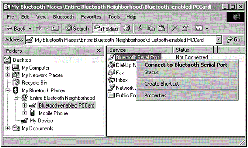
Figure 6-4. Right-clicking the device icon causes a pop-up menu to appear; the menu offers the ability to enable the serial port emulation. (Courtesy TDK Systems Europe.)
In some instances, the user may have to enable this serial port for it to be offered by the operating system, which then can be subsequently offered to the legacy application. In Figure 6-4, the user can either double-click [4] the serial port icon or right-click its icon to begin the process of enabling the device.
In Figure 6-5, we now see the Microsoft Windows Device Manager offers the emulated (or virtual [5]) serial ports. Since the virtual ports have been enabled and made available to the operating system, configuration of the port properties can be performed, as seen in Figure 6-6.
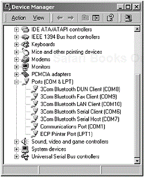
Figure 6-5. In the Microsoft Windows Device Manager, the Bluetooth Virtual Serial Port [6] has been configured ready for use by any legacy application. (The 3Com Bluetooth Connection Manager has registered with the operating system a range of virtual serial ports that are ready for use.)

Figure 6-6. When the port is available for application use, its configuration and properties (such as baud rate and data bits) can be managed accordingly. The 3Com Bluetooth Connection Manager has registered with the operating system a range of virtual serial ports, which can now be configured by the user.
A legacy application makes use of the emulated serial port model and is therefore classed as a Type I device. The operating system would be offered the virtual serial port through the Bluetooth aware helper application, which we will discuss later in this chapter.
The purpose of making the distinction between these types of applications is to clarify and understand the composition of RFCOMM. In this particular application context, the creation of an emulated serial port would be transparent to the user. Let us take a look back at Table 6-1; all of these profiles are dependent on the operation of the Serial Port Profile and, as such, each requires the establishment of an emulated serial port as part of their communication link with the remote device.
The phrase “cable replacement application” is not introduced in the profile itself, but is introduced here to attempt to distinguish between the different usages available. It refers to specific Bluetooth applications that create implicit emulated serial ports. These ports remain transparent to the user in order to complete the creation of a communications link; we discuss this in more detail later in this chapter.
The cable replacement application can also be classed as a Type I device. The specific profile would be implemented to use the Bluetooth aware helper application, through an Application Programming Interface (API).
This type of application would form part of the communications link, but would still remain transparent to all communicating parties. Figure 6-7 illustrates three devices; DeviceA and DeviceB have Bluetooth capability, whereas DeviceC is a non-Bluetooth device, such as a wired modem.

Figure 6-7. Three devices form part of this communication link for it to reach the services of the remote party.
DeviceA would communicate with DeviceB through the emulated serial port capability in order to provide DeviceA the service of DeviceC. The provision of services of the device pair (B and C) would be similar to the usage models provided by the legacy and cable replacement application.
The intermediate application completes a wired connection (a physical serial port) and is therefore classed as a Type II device. Some aspects of a Bluetooth aware helper application may be used to provide the completed and transparent communications link to DeviceC.
In Figure 6-8, we illustrate the structure of the Bluetooth protocol stack layers with the Type I and Type II applications in mind. In the figure, we can see the two types of applications; of particular interest is the Type II structure, where the Helper-aware application interfaces directly to the physical interface of a Data Communication Equipment (DCE) device such as a modem. You will also notice that the Bluetooth helper aware application is accompanied with an additional entity. These entities are used to understand how each type of application interacts with the outside world. The Port Emulation Entity is used to describe the API that interfaces to the RFCOMM layer, whereas the Port Proxy Entity relays RFCOMM-specific data to the physical serial interface. These are two conceptual structures, which are used to illustrate the two different natures of providing an RFCOMM service.
Legacy, cable replacement and intermediate applications rely on the use of a Bluetooth aware helper application. It achieves this through an API, which is provided to developers when building high-level Bluetooth applications that utilise the emulated serial port function—thus providing an interface to the RFCOMM layer accessing its core functionality. Typically, this is implementation specific and can be managed at various levels on a development platform, such as an embedded or device driver [7] environment. Furthermore, the purpose of this helper aware application is to assist in establishing a legacy and cable replacement application, a virtual serial port presence without disruption to the operating system environment.
Table 6-2. Typical APIs that would be used to open and close a communications link as well as transmit and receive data.
|
API |
DESCRIPTION |
|---|---|
|
|
An API function that would be used to open or create a communications link with the peer device. |
|
|
An API function that would be used to close or disconnect a communications link with the peer device. |
|
|
An API function that would be used to transmit data to the peer device. |
|
|
An API function that would be used to receive data from the peer device. |
Essentially, it succeeds in disguising the underlying wireless transport, which forms most of the Bluetooth protocol stack, and provides a constructive interface to quickly and effectively deploy a communications link.
The two sections that follow provide examples of an implementation on two separate platforms and the role that a helper application would fulfil. In both instances, a common interface can be provided to enable a developer access to the core functionality. In Table 6-2, we identify some common APIs that may be used to routinely exchange data between peer devices and to establish and disconnect the communications link.
In the previous examples, we illustrated the presentation of a virtual serial port to the operating system where it could employ the use of that port for legacy type applications. In such implementations, the upper-edge of the helper aware application would expose its interface as a serial port and its lower-edge would present itself to the Bluetooth protocol stack, via an API as we illustrated in Table 6-2. This, in turn, provides a transparent wireless transport for the legacy application and other applications that wish to make use of that service.
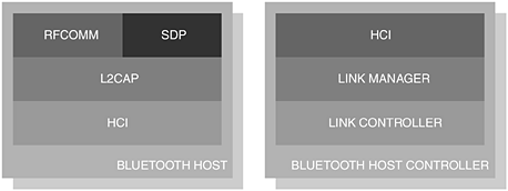
Introducing Bluetooth to the Microsoft Windows environment would comprise a host and a host controller. The host would consist of a Bluetooth library, which contains sufficient software to exist in the new environment and would have sufficient knowledge about the various transport mechanisms, that is, PC Card or USB. In this particular context, the host controller would be enumerated by the Microsoft Windows operating system and, in turn, would acknowledge to the host that it exists. This would be achieved by asking Microsoft Windows to add new hardware or through the automated process of introducing the new hardware to the environment, in other words inserting a Bluetooth-enabled PC Card or USB dongle. In most Bluetooth implementations, the host software is active, but no Bluetooth-specific activity is present, since there is no host controller to interact with it. When making available this new device, a number of services will be registered with the operating system. In our earlier illustration, Figure 6-5, the Device Manger recognised the numerous non-standard communications ports.
In Figure 6-9, we illustrate the host and host controller components that are typical of a Bluetooth implementation. Such an environment can be constructed using the Microsoft Windows Driver Model (WDM), an architecture, which is inherent in the various development kits currently available.
In this particular instance, an embedded application would provide a minimal set of API function calls in order to quickly facilitate the communications link to the peer device; we illustrated in Table 6-2 some of the possible functions that may be available to a developer.
Embedded applications, such as a LAN Access Point (LAP) as presented in the LAN Access Profile, Chapter 10, would simply require the communications link to be established transparently. These types of applications would not necessarily advertise a specific serial port service. In the case of the LAP, the LAN Access service would be advertised; this holds well with our explanation of a Cable Replacement Application, as illustrated in our earlier sections. In this context, implementation will vary. With the availability of a Bluetooth protocol stack in one environment, there may be no need to have the host and host controller divide. You may recall that in a Microsoft Windows environment the division of host and host controller was made, as we can see in Figure 6-9.
The profile outlines no specific roles for participating devices, although it does distinguish between the behaviour of initiator and acceptor.
In Table 6-3, clarification is provided with regard to the roles used within the context of this profile. In general, DeviceA represents the initiating party and DeviceB represents the accepting party. The terms are often used interchangeably, when describing specific operations in various contexts and are provided here for reference.
There is no distinction made between a master or a slave device in this profile. The relationship exists at the peer-to-peer level. For completeness, the typical scenario created by a Data Terminal Equipment (DTE) and a DCE can easily be mapped onto DeviceA and DeviceB, respectively. In Figure 6-10, we can see how the Serial Port components are integrated with the existing Bluetooth protocol stack.
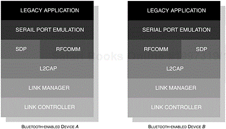
Figure 6-10. The core components of the Bluetooth protocol stack are shown illustrating how the components of the Serial Port Profile are integrated.
The RFCOMM layer has been architected to provide an independent structure, where concurrent connections can be maintained. In Figure 6-11, we illustrate NotebookB maintaining multiple connections with NotebookA and NotebookC.
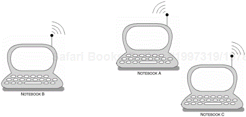
Figure 6-11. This usage model demonstrates the ability to maintain multiple serial connections with many devices. NotebookB maintains a serial connection with NotebookA and NotebookC.
Table 6-3. The list of behavioural characteristics that are typical for this profile.
|
CONFIGURATION |
ROLE |
DESCRIPTION |
|---|---|---|
|
DeviceA |
Initiator |
This configuration describes the device that instigates the original connection or the device that wishes to initiate communication over an existing link. |
|
DeviceB |
Acceptor |
This configuration describes the process of the device accepting the initiated communication from DeviceA. |
The use of authentication and encryption is optional. However, if one device in the relationship requires authentication or encryption, then the participating device should enable the same level of support.
A large part of the emulated serial communication is typically transparent to the user, alleviating some of the potential complexities involved when configuring legacy serial port-based applications. Here the user is presented with a set of parameters that needs to be determined accurately for the user to create a successful connection with the peer device, although RFCOMM does not strictly impose these restrictions.
Removing this complexity provides a greater sense of ‘ease-of-use’ for the user, who often does not care about the internal nature of a serial port configuration. With a greater adoption of Bluetooth technology as a means to wireless cable replacement, the typical legacy application would be created in such a manner as to provide transparency, thereby alleviating the user from configuring standard serial port parameters.
In establishing a connection with a peer device to make use of the emulated serial port service, DeviceA initiates the connection by performing inquiry and device discovery procedures. The user may also be given the flexibility to choose specific services available to it through the browsing capabilities. The RFCOMM Server channel number is then made available, which will begin the process of initiating and creating an L2CAP channel for the remote device which in turn, starts a new RFCOMM session using the Server channel number; Figure 6-12 provides an illustration of the events that may occur. We discuss the architecture of the RFCOMM protocol later on in this chapter.
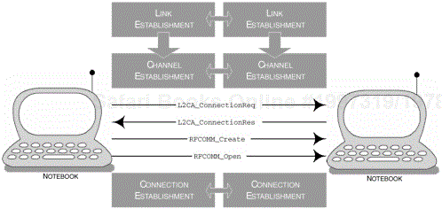
Figure 6-12. The events that take place during the set-up and establishment of a serial communications link.
If any existing RFCOMM session is available when a new connection is being established, then the data connection should be created on the existing session; more detail of the procedures for setting up a connection is provided in Section 6.5.1.2, The RFCOMM Protocol.
Now that we have discussed both existing and future usage models and their respective user expectations, in the following sections, we can an opportunity to explore in greater depth the dependencies that make up this profile. In Figure 6-13, we provide a conceptual illustration representing the dependencies that make up the Serial Port Profile; the areas that are shaded are relevant to this profile. As you can see, the profile depends upon the basic functionality offered to us by the Generic Access Profile, Chapter 2 and the Service Discovery Application Profile, Chapter 3. We will now discuss, in turn, the basic requirements of these dependent components and any deviations that may occur from the basic functionality originally offered to us.
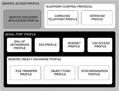
Figure 6-13. The dependent components of the Bluetooth protocol stack that make up the Serial Port Profile. The areas that are shaded are relevant to this profile.
The Service Discovery Application Profile, Chapter 3, introduced the characteristics of the mechanisms used to retrieve service information from a remote device. Typically, a client will initiate inquiry and discovery procedures as previously outlined, to learn of the devices in radio range. A client can then make use of an application, carrying the functionality of the underlying Service Discovery Protocol (SDP). The Service Discovery Application (SrvDscApp) uses an SDP Client to instigate a request to the remote device where the SDP Server will respond; as such, DeviceA and DeviceB must employ the use of an SDP client and server, as illustrated in Table 6-4.
Protocol Data Units (PDUs) are used to instruct the SDP server to undertake browsing procedures and to retrieve service record information. You may recall that the PDUs carry payloads about requests containing AttributeIDs and AttributeValues, which describe exactly what is being sought. As we previously discussed, the client and server operate a request and response paradigm. SDAP will construct PDUs containing information relating to the AttributeID and AttributeValues, in turn, instructing the server to carry out its operation. The various request and response PDUs that are required are shown in Table 6-5, where features indicated are described as mandatory (M), optional (O) and excluded (X).
Table 6-4. As a minimum, the local device must support the use of a client application and the remote device must support the use of a server.
|
FEATURE |
DEVICEA |
DEVICEB |
|---|---|---|
|
SDP Client |
M |
X |
|
SDP Server |
X |
M |
A service record is maintained for each service a device is capable of supporting and, as such, a Service Record Handle is created to uniquely identify this. The ServiceRecordHandle is a 32-bit unsigned integer and is stored on the SDP server. The service record shown in Table 6-6 identifies a device that supports Serial Port emulation and provides a list of AttributeIDs, which ultimately would identify the service for the Serial Port Profile. A minimum of two attributes are required to make a service record (ServiceRecordHandle and ServiceClassIDList), where it must contain at least one UUID.
When browsing for services on the remote device, a local device constructs a search pattern using a Universally Unique Identifier (UUID). A UUID is a 128-bit value, which has been shortened for use within Bluetooth applications. The shortcut has been provided by first establishing a Bluetooth Base UUID, which we discussed in the Service Discovery Application Profile, Chapter 3.
The UUIDs that have been presented so far in this chapter are aliases and take the form of what is referred to as a 16-bit UUID or a 32-bit UUID but, in turn, they all should refer to the 128-bit notation. These UUIDs have been assigned and can be referenced in the Bluetooth Special Interest Group, Bluetooth Assigned Numbers, v1.1, February 2001. Since they will all be compared at this range, they all need to be converted to the 128-bit notation. This needs to be done for the search pattern to be successful. An arithmetic conversion algorithm is used to construct the 128-bit value.
Table 6-5. The list of PDUs that are required for the operation of the Serial Port Profile.
|
PDU |
DEVICEA |
DEVICEB |
|---|---|---|
|
|
X |
M |
|
|
M |
X |
|
|
X |
M |
|
|
M |
X |
|
|
X |
M |
|
|
O |
X |
|
|
X |
O |
Table 6-6. The list of mandatory and configurable items that make up this profile’s service discovery record.
|
ATTRIBUTE |
DESCRIPTION |
|---|---|
|
|
With an |
ServiceClassIDList ServiceClass0 |
With an |
ProtocolDescriptorList
  Protocol0
  Protocol1
ParameterFor1 |
With an |
BluetoothProfile
DescriptorList
  Profile0
ParameterFor0 |
With an |
|
|
With a base |
Table 6-7 summarises the service class UUIDs used to identify the particular profile in use; this also correlates with the identification of the device during a device discovery procedure.
As part of the service record, the dependent underlying protocols are also identified. The local device retrieves this information where it can fully understand the exact requirements needed to fulfil the service. The Serial Port Profile is dependent on the protocols as shown in Table 6-8; the table also shows their associated UUID values.
We touched upon the fact that the Serial Port Profile relies upon RFCOMM to provide an emulated serial port presence. Our focus here is to describe the processes used to provide such a service and to establish how the underlying Bluetooth transport is facilitated in achieving this. In doing so, we will develop a fuller understanding of how the various types of applications are supported, that is, Type I and Type II. You may recall from our earlier discussion that Type I devices support an emulated transparent presence, which underlies most of the profiles. Type II devices are intermediary applications, which will ultimately interface with a physical connection.
RFCOMM has been designed to sit above the L2CAP component of the Bluetooth protocol stack, as shown in our earlier illustrations. In our first look at understanding this protocol, we will examine its architecture in more detail and then consider specific aspects of integration over L2CAP. In later sections, we will also discuss how the RFCOMM protocol is used to transport data between peer devices. In our first look at the RFCOMM protocol, we consider how the physical serial port is emulated in software.
RFCOMM is based upon the European Telecommunications Standards Institute (ETSI) digital cellular telecommunications system (Phase 2+); Terminal Equipment to Mobile Station (TE-MS) multiplexer protocol (GSM 07.10 Version 6.3.0) specification. [8] The RFCOMM layer emulates RS232 serial ports, where there is also provision for null modem capability. In Table 6-9, we identify the typical 9-circuits of an RS232 serial interface.
When two Bluetooth-enabled devices are connected, that, is two Data Terminal Equipment (DTE) devices, a null modem connection is created. The translation of these signals is shown in Table 6-10, which shows how the RFCOMM signals are mapped onto RS232 control signals. Some devices will be capable of using RS232 control signals, whereas other Bluetooth devices may not. As such, no peer device should be dependent upon receiving this information. To ensure interoperability, the control signals’ parameters must be set to default on devices that are using them. These may be defined using the Bluetooth aware helper application, where the parameters are determined through the RFCOMM Data Link Connection (DLC) stage; there will be more about this later on. The use of control signals is optional, although flow control, Ready-to-Receive (RTR), can be mapped onto Ready-to-Send (RTS) and Clear-to-Send (CTS), again using the helper application. These mappings are shown in Table 6-10.
Table 6-8. The list of protocols that are used in this profile; their associated UUID values are also shown.
|
PROTOCOL |
UUID |
|---|---|
|
|
|
|
|
|
Table 6-9. The list of RS232 circuits that are emulated in RFCOMM.
|
CIRCUIT |
|---|
|
Signal Common |
|
Transmit Data (TD) |
|
Received Data (RD) |
|
Request to Send (RTS) |
|
Clear to Send (CTS) |
|
Data Set Ready (DSR) |
|
Data Terminal Ready (DTR) |
|
Data Carrier Detect (DCD) |
|
Ring Indicator (RI) |
The RFCOMM DLC state may dictate that the Data Set Ready (DSR), Data Terminal Ready (DTR) and Data Carrier Detect (DCD) are set to high when creating a new DLC. Doing so indicates that the device is ready; conversely, they should be set to low when the connection has terminated.
Table 6-10. In the list of signals, we illustrate how the emulated RFCOMM signals are mapped onto the RS232 signals.
|
RFCOMM SIGNALS |
RS232 SIGNALS |
|---|---|
|
Ready to Communicate (RTC) |
DSR, DTR |
|
Ready to Receive (RTR) |
RTS, CTS |
|
Incoming Call Indicator (IC) |
RI |
|
Data Valid (DV) |
DCD |
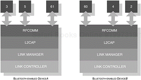
In a typical scenario, a notebook or PC would be supplied with one or two RS232 serial port connectors. RFCOMM is capable of supporting up to 60 emulated serial connections, where a unique identifier is assigned for each active connection between two Bluetooth-enabled devices; we will discuss in some more detail the structure of these identifiers later on in this chapter. The provision to support multiple RFCOMM connections is optional and is therefore implementation-specific. In Figure 6-14, we illustrate the conceptual nature of multiple connections with two Bluetooth devices, where each connection maintains its own Channel Identifier (CID) with L2CAP.
The Bluetooth aware helper application is exposed to a legacy application and it will encompass the use of a port emulation entity. As we touched upon earlier, this provides us with a useful reference model, which the profile refers to as the service definition model.
In Figure 6-15 and Table 6-11, we illustrate the structure of these entities and offer an explanation of how each entity interacts with one another. In the previous section, we reinforced the conceptual nature of how each layer interacts and how an emulated serial port service manifests itself to an end-user legacy application. We now turn our attention to the specific structures that make up the transport capability and examine in greater detail RFCOMM frame types and commands.
In Figure 6-16, we illustrate the RFCOMM frame structure that is used to transport serial data between peer devices. Each device within the communicating party may have a client and server application, concurrently managing multiple sessions in either direction. A DLC is established between two devices when there is an active connection. In the ETSI TS 101.369 specification, a Data Link Connection Identifier (DLCI) is used to distinguish between connections that have been established; it forms the Address field of the frame structure and is illustrated for reference in Figure 6-17. For Bluetooth applications, this structure has been modified to accommodate the concept of an RFCOMM Server Channel and a Direction Bit (D); we illustrate the format of this adapted structure in Figure 6-18; you have already come across the RFCOMM Server Channel concept in Section 6.5.1.1, Service Discovery, where this channel is registered with the service record.
Table 6-11. The list of key components that are used to provide an emulated serial port service.
|
ENTITY |
DESCRIPTION |
|---|---|
|
Legacy Application |
The end application that will ultimately make use of the serial port services. |
|
Aware Helper Application |
This application provides the port emulation entity, which also exposes the API to the legacy application. The port emulation entity will also know how to interact with the RFCOMM layer. |
|
RFCOMM |
The entity that provides the serial transport mechanism, which subsequently maintains a CID with the L2CAP layer. |
|
SDP |
This layer advertises available RFCOMM services to other interested devices in radio range. |
|
L2CAP |
This layer provides segmentation and reassembly (S&R) services, as well as multiplexing capabilities. |
An RFCOMM server application registers the server channel number in the service record, where the channel numbers are in the range of 1 to 30. On closer inspection of Figure 6-18, we can see that the Server Channel field is made up of 5-bits, thus providing a potential range of 0 to 31. However, server channel 0 is reserved for transmitting control messages and channel 31 is reserved for backward compatibility with ETSI TS 101.369 specific applications.
The initiating device (DeviceA) is assigned the Direction Bit of 1, whereas the corresponding session at DeviceB is assigned the Direction Bit of 0. We introduced earlier that RFCOMM is capable of managing up to 60 concurrent sessions. This is achieved through the assignment of 30 channels in one direction and 30 channels in the opposing direction. Essentially, the DLCI assignments for DeviceA are available in the range of 3, 5, 7 and so on to 61. DeviceB follows a similar pattern, where the DLCI assignment forms the range of 2, 4, 6 and so on to 60.
In ETSI TS 101.369, the Extended Address can be extended over several octets. For the purpose of Bluetooth-enabled applications, the Extended Address field is always assigned the value 1. Thus, the address of a session is managed by the DLCI, that is, the combination of D and the ServerChannel. An assignment of 0 would indicate that the address follows over several octets.
Before looking at the Command/Response (C/R) field, we need to consider the availability of frame types in RFCOMM; these are presented in Table 6-12. These frames allow RFCOMM to create and control sessions with its peer device. When a command is sent to the peer device, a response will be expected.
In Table 6-13, we illustrate the general notation used to reflect the C/R bit. When the initiator wishes to establish the first connection, the SABM frame is used and carried over DLCI(0); the responder (DeviceB) will reply with the UA frame, which is also on DLCI(0). You may recall from our earlier discussion that DLCI(0) represents our control channel. As such, commands and responses from the initiator will always have the C/R bit set to 1; whereas commands and responses initiated by the responder will always have the C/R bit set to 0. Any data being exchanged between the initiator and responder will carry the C/R bit set to 1 and 0, respectively.
Looking back at our earlier illustration Figure 6-16, the next field forming the RFCOMM frame is the Control field. This field is used to identify the type of frame being carried in the payload. The Control field is 8-bits in length and its structure is shown in Table 6-14.
You will notice that bit 4 has been omitted from the table and is referred to as the Poll/Final (P/F) bit. The representation of this bit is twofold: in a command, the P-bit representation is used, whereas the F-bit representation is used for a response. As such, the value of the P/F bit is determined by the command or response payload.
Table 6-12. The available frame types that are supported by RFCOMM.
|
FRAMES |
|---|
|
Set Asynchronous Balanced Mode (SABM) |
|
Unnumbered Acknowledgement (UA) |
|
Disconnected Mode (DM) |
|
Disconnect (DISC) |
|
Unnumbered Information with Header check (UIH) |
Table 6-13. The representation of the C/R bit used within the Address field.
|
DIRECTION |
C/R | |
|---|---|---|
|
COMMAND |
Initiator to Responder |
1 |
|
Responder to Initiator |
0 | |
|
RESPONSE |
Initiator to Responder |
0 |
|
Responder to Initiator |
1 |
A payload may need to be carried over several frames; as such, the P bit is set to 1 in a command, where a responder needs to carry its payload over several frames. The responder device provides its frame with the F bit set to 1, acknowledging that more payloads are to follow. Some exceptions of this rule apply to SABM and DISC frames; if the P/F-bit is set to 0, then these frames are discarded. Furthermore, if a spontaneous DM frame is received, then the corresponding device will process the payload regardless of the P/F-bit setting.
In our earlier figure, we showed a Length field of two bytes. However, the length of this field may be constructed using one or two bytes, which depends upon the size of the data or payload to be carried. The Length field itself is also constructed using an Extended Address (EA); we illustrate this representation for one and two bytes in Figure 6-19 and Figure 6-20, respectively.
The EA field is used to denote that the Length field has been extended. If EA is set to 0, then the size of the Length field is two bytes and conversely, if the EA-bit is set to 1, then the Length field occupies one byte.
We now turn our attention to the Data field, which is always carried using UIH frames. The default length for an RFCOMM frame is 32-bytes, whereas the maximum payload, as specified by the Length field (over two bytes), is 32,767-bytes. Payload size is typically determined by the L2CAP layer’s Maximum Transmission Unit (MTU). Essentially, the maximum size of a payload in an RFCOMM frame is proportional to the MTU.
Table 6-14. The encoding of the frame type in the Control field.
|
FRAME | ||||||||
|---|---|---|---|---|---|---|---|---|
|
7 |
6 |
5 |
4 |
3 |
2 |
1 |
0 |
Bit # of Control Field |
|
0 |
0 |
1 |
x |
1 |
1 |
1 |
1 |
SABM |
|
0 |
1 |
1 |
x |
0 |
0 |
1 |
1 |
UA |
|
0 |
0 |
0 |
x |
1 |
1 |
1 |
1 |
DM |
|
0 |
1 |
0 |
x |
0 |
0 |
1 |
1 |
DISC |
|
1 |
1 |
1 |
x |
1 |
1 |
1 |
1 |
UIH |
The Frame Check Sequence (FCS) field is used to verify the payload. In summary, for SABM, DISC, UA and DM frames, the FCS is calculated on the Address, Control and Length fields. For UIH frames, the FCS field is calculated on the Address and Control fields.
In a typical physical environment, DTE and DCE devices will use a flow control mechanism to regulate communication between the two devices. A wired environment would have available flow control represented as Transmission On/Off (XON/XOFF), RTS/CTS or DTR/DSR. You may recall from our earlier discussion how these signals are mapped in RFCOMM; the use of flow control is optional.
Before continuing our discussion on the use of flow control within RFCOMM, an introduction of the available commands would be useful; these are illustrated in Table 6-15. The FCON/FCOFF and MSC commands are of particular relevance to our flow control discussion; we will discuss the encoding of these commands and other commands in more detail later in this section.
RFCOMM provides two flow control mechanisms. The first affects all RFCOMM frames, that is, the aggregate data flow between two devices. This, in turn, relies upon the FCON/FCOFF command structure. The second affects the individual server channel or DLCI which in turn, is managed through the MSC command. These two mechanisms regulate flow control of UIH frames, which are data payloads being exchanged between peer devices. Flow control has to be negotiated during DLC establishment, since backward compatibility must be retained for earlier versions of Bluetooth-enabled applications.
Table 6-15. The available commands that are supported by RFCOMM.
|
COMMANDS |
|---|
|
Test |
|
Flow Control On (FCON) |
|
Flow Control Off (FCOFF) |
|
Modem Status Command (MSC) |
|
Remote Port Negotiation (RPN) |
|
Remote Line Status (RLS) |
|
DLC Parameter Negotiation (PN) |
|
Non Supported Command (NSC) |
You may recall from our earlier discussion that Type I and Type II devices are supported by RFCOMM. Our discussion now turns to support of flow control for these two different types of applications. An application may request flow control support—as such, it must be managed accordingly by RFCOMM. To a greater extent, the RFCOMM protocol can ignore some of the parameters defined by the higher-level legacy application and rely upon its own flow control system. This potentially introduces problems, since RFCOMM and its underlying layers are managing the flow of data between the peer devices. In some circumstances, this may cause confusion for the intended application, since it may be relying on an accurate flow of data. In these instances, the flow control mechanism used by RFCOMM should provide some intelligence to the way it adapts the flow control philosophy. In turn, RFCOMM must do its best to emulate the wired environment, where a combination of flow control mechanisms may also be used; for example, if XON/XOFF support has been selected in the application, then RFCOMM should mirror that same support.
In the latest Bluetooth specification, credit based flow control has been introduced and has become a mandatory feature. Support is noted within the RFCOMM frame and a frame that supports credit based flow control is illustrated in Figure 6-21. It is a feature that provides flow control on a connection basis.
Both peer devices keep a tally of the number of frames that have been sent to each and, as such, each device knows how many more frames can be sent before their respective buffers fill up. The notion of a credit system is used and while each device has credits, each party can continue sending frames. If a credit reaches zero, then the peer device must pause its transmission until further credits are received.
The amount of credits used for each peer is established during Parameter Negotiation (PN), which occurs prior to DLC establishment; we discuss PN in more detail in Section 6.5.1.2.5.6, Parameter Negotiation (PN).
In Table 6-15, we introduced the various commands and responses, where FCON/FCOFF and MSC are used to manage and coordinate flow control within the RFCOMM protocol. In this section, we will introduce how these various commands and responses are encoded within the RFCOMM frame. We will also consider the credit based flow control mechanism that has been introduced into the latest Bluetooth specification.
In our earlier illustration Figure 6-16, we showed the RFCOMM frame, where the Data field contained information to be transported to its peer. In Figure 6-22, we illustrate the structure used to encode commands and responses.

Figure 6-22. The structure of an encoded command or response within the Data field of an RFCOMM frame.
Commands and responses are all encoded within the UIH frame. The illustration shows us that a Type, Length and Value field make up this new structure. The Type field is further constructed of an Extended Address and a C/R field, which are both similar in nature to our earlier introduction. The EA field is always set to 1, since the Type field always occupies 1-byte and the C/R-bit is used to denote a command or response within the Value field.
The Type field value is assigned, depending upon the command or response being carried out. In Table 6-16, we identify the various values available. Figure 6-23 illustrates the encoded command or response within the RFCOMM frame.
In the following sections, we visit each command and response and examine each structure in detail.
This simple command assures the reliability of the communications link between the peer devices. The EA field is set to 1 and the C/R field is set to reflect a command or response. The Type field is assigned the value as shown in Table 6-16 and the Length field is assigned the number of bytes contained within the structure. This payload is transmitted to the peer, where it will respond with exactly the same number of bytes as the original payload. This method is used to verify the integrity of the connection.
These commands are used to regulate the aggregate data flow over the RFCOMM connection. The EA field is set to 1 and the C/R field is set to reflect a command or response. The Type field is assigned the value as shown in Table 6-16 and the Length field is set to zero, since there is no data to carry, other than the acknowledgement of FCON/FCOFF.
During credit based flow control, the FCON/FCOFF control commands should not be used.
This command provides the emulated control signals onto the communications link between the peer devices. The EA field is set to 1 and the C/R field is set to reflect a command or response. The Type field is assigned the value as shown in Table 6-16 and the Length field is assigned the value two or three. The MSC structure is illustrated in Figure 6-24, where we can see the Type, Length, DLCI, Signals and Break Signals fields. The DLCI field contains the server channel or active DLC value for which the MSC is to be applied; this follows the same structure as illustrated in Figure 6-18.

Figure 6-24. The structure of an encoded command or response within the Data field of an RFCOMM frame showing the inclusion of the Break Signals' field.
The new Signal field represents the mapped RS232 signals, which were identified in Table 6-10; we illustrate this structure in Figure 6-25. You will also notice in Figure 6-24 the availability of the Break Signals field, which is optional; however, its structure is shown in Figure 6-26. In Table 6-17 and Table 6-18, we offer an explanation and usage of the various fields that make up these two new structures.
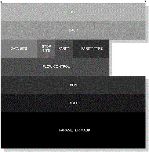
This command sets the communication settings, where both devices must ensure that these settings have been defined prior to sending data. The EA field is set to 1 and the C/R field is set to reflect a command or response. The Type field is assigned the value as shown in Table 6-16 and the Length field is assigned the value one or eight. In Figure 6-27, we illustrate the parameters that make up the RPN command for an 8-byte length.
The following parameters typically make up the options available at the user-level application, as we witnessed in Figure 6-6. The Baud field represents the baud setting, where the default value is 9600 baud; the other available settings are shown in Table 6-19 and are mapped accordingly. The Data Bits field values are illustrated in Table 6-20, where the default setting is 8-bits.
Table 6-17. The Signal fields and their usage within MSC.
|
FIELD |
DESCRIPTION |
|---|---|
|
EA |
This field is set to 1, since there is only 1-byte of information. |
|
FC |
This field is set to 1, when it is not able to accept RFCOMM frames. During credit based flow control, this bit should be set to 0, as it has no meaning for the acceptor device. |
|
RTC |
This field is set to 1, when the device is ready to communicate. |
|
RTR |
This field is set to 1, when the device is ready to receive data. |
|
IC |
This field is set to 1, indicating an incoming call. |
|
DV |
This field is set to 1, indicating that data valid has been sent. |
Table 6-18. The Break Signal fields and their usage within MSC.
|
FIELD |
DESCRIPTION |
|---|---|
|
EA |
This field is set to 1, since there is only 1-byte of information. |
|
BREAK |
This field is set to 1, indicating that a break signal is encoded. |
|
LENGTH |
This field contains the length of the break in units of 200ms. |
The Stop Bit field has a default value of 0, which represents 1 stop bit; other values include 1, representing 1.5 stop bits. The Parity field has a default value of 0, representing no parity, whereas 1 represents parity.
In Table 6-21, we illustrate the available values for the Parity Type field and in Table 6-22 we illustrate the available values for the Flow Control field, where the default value is 0, representing no flow control. You may recall that these signals are mapped so that RTR is mapped to CTS and RTC is mapped to DTR/DSR. The XON/XOFF field settings are mapped to the default settings of DC1/DC3, respectively.
Table 6-19. Baud settings and their usage within the RPN command.
|
BAUD | ||||||||
|---|---|---|---|---|---|---|---|---|
|
7 |
6 |
5 |
4 |
3 |
2 |
1 |
0 |
Bit # of Baud Field |
|
0 |
0 |
0 |
0 |
0 |
0 |
0 |
0 |
2500 bits/s |
|
0 |
0 |
0 |
0 |
0 |
0 |
0 |
1 |
4800 bits/s |
|
0 |
0 |
0 |
0 |
0 |
0 |
1 |
0 |
7200 bits/s |
|
0 |
0 |
0 |
0 |
0 |
0 |
1 |
1 |
9600 bits/s |
|
0 |
0 |
0 |
0 |
0 |
1 |
0 |
0 |
19200 bits/s |
|
0 |
0 |
0 |
0 |
0 |
1 |
0 |
1 |
38400 bits/s |
|
0 |
0 |
0 |
0 |
0 |
1 |
1 |
0 |
57600 bits/s |
|
0 |
0 |
0 |
0 |
0 |
1 |
1 |
1 |
115200 bits/s |
|
0 |
0 |
0 |
0 |
1 |
0 |
0 |
0 |
230400 bits/s |
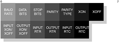
In our final Parameter Mask field, the available values for the first 8-bits are defined in Table 6-23 and the second set are defined in Table 6-24. These values are set according to what will be negotiated as part of the RPN command.
In general, the mask will be interpreted for a command as 1, change and 0, no change; for a response, the interpretation will be 0, not accepted and 1, accepted. For reference purposes, the parameter mask is illustrated in Figure 6-28.
This command is optional and is used to indicate the RLS status of the current connection; in a typical scenario, it informs the other end of an error. The EA field is set to 1 and the C/R field is set to reflect a command or response. The Type field is assigned the value as shown in Table 6-16 and the Length field is assigned the value two. In Figure 6-29, we illustrate the parameters that make up the RLS command.
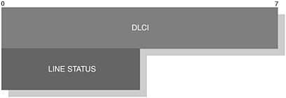
Figure 6-29. The RLS fields represented by two bytes, where the blank spaces represent reserved areas.
Table 6-20. Data Bits settings and their usage within the RPN command.
|
DATA BITS | ||
|---|---|---|
|
1 |
0 |
Bit # of Data Bits Field |
|
0 |
0 |
5-bits |
|
0 |
1 |
6-bits |
|
1 |
0 |
7-bits |
|
1 |
1 |
8-bits |
Table 6-21. Parity Type settings and their usage within the RPN command.
|
PARITY TYPE | ||
|---|---|---|
|
5 |
4 |
Bit # of Parity Type Field |
|
0 |
0 |
Odd Parity |
|
0 |
1 |
Even Parity |
|
1 |
0 |
Mark Parity |
|
1 |
1 |
Space Parity |
The DLCI field is constructed in the usual manner as presented in earlier sections and in Table 6-25 we present the available values for the Line Status field, where a default value of 0 indicates no error and bit 0, at value 1, will indicate an error.
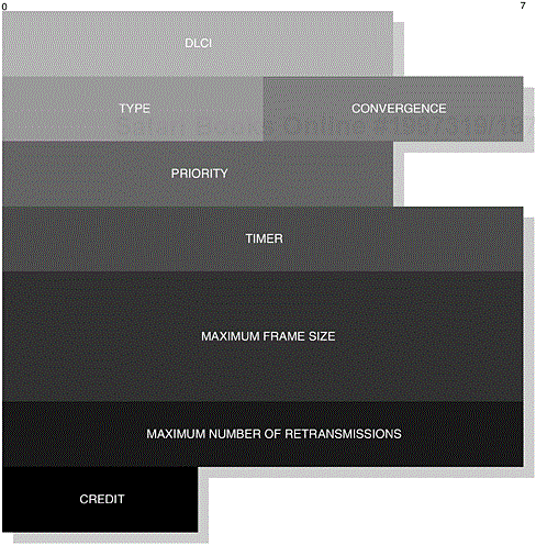
In our earlier discussion, we introduced the notion that a new DLC is established for every RFCOMM session. As such, a set of parameters are negotiated prior to session establishment. PN is used to define the set of parameters that will be used for a new DLC, see Figure 6-30. The EA field is set to 1 and the C/R field is set to reflect a command or response. The Type field is assigned the value as shown in Table 6-16 and the Length field is assigned the value eight.
The DLCI field is constructed in the usual manner as presented in our earlier sections. The Type field value identifies the type of RFCOMM frame being used and in this instance it has the value 0, since an UIH frame is being used. The Convergence field represents the type of convergence layer being used and in all cases the default is Type I (unstructured octet streams). The Priority field, as the name suggests, represents the urgency of the frame, where 0 represents the lowest priority and 63 represents the highest priority.
Table 6-22. The Flow Control and their usage within the RPN command.
|
FLOW CONTROL | ||||||
|---|---|---|---|---|---|---|
|
5 |
4 |
3 |
2 |
1 |
0 |
Bit # of Flow Control Field |
|
0 |
0 |
0 |
0 |
0 |
0 |
No Flow Control |
|
0 |
0 |
0 |
0 |
0 |
1 |
XON/XOFF on Input |
|
0 |
0 |
0 |
0 |
1 |
0 |
XON/XOFF on Output |
|
0 |
0 |
0 |
1 |
0 |
0 |
RTR on Input |
|
0 |
0 |
1 |
0 |
0 |
0 |
RTR on Output |
|
0 |
1 |
0 |
0 |
0 |
0 |
RTC on Input |
|
1 |
0 |
0 |
0 |
0 |
0 |
RTC on Output |
Table 6-23. The Parameter Mask (1st Byte) and their usage within the RPN command.
|
PARAMETER MASK 1st BYTE | ||||||||
|---|---|---|---|---|---|---|---|---|
|
7 |
6 |
5 |
4 |
3 |
2 |
1 |
0 |
Bit # of Parameter Byte |
|
0 |
0 |
0 |
0 |
0 |
0 |
0 |
1 |
Baud Rate |
|
0 |
0 |
0 |
0 |
0 |
0 |
1 |
0 |
Data Bits |
|
0 |
0 |
0 |
0 |
0 |
1 |
0 |
0 |
Stop Bits |
|
0 |
0 |
0 |
0 |
1 |
0 |
0 |
0 |
Parity |
|
0 |
0 |
0 |
1 |
0 |
0 |
0 |
0 |
Parity Type |
|
0 |
0 |
1 |
0 |
0 |
0 |
0 |
0 |
XON Character |
|
0 |
1 |
0 |
0 |
0 |
0 |
0 |
0 |
XOFF Character |
Table 6-24. The Parameter Mask (2nd Byte) and their usage within the RPN command.
|
PARAMETER MASK 2nd BYTE | ||||||||
|---|---|---|---|---|---|---|---|---|
|
7 |
6 |
5 |
4 |
3 |
2 |
1 |
0 |
Bit # of Parameter Byte |
|
0 |
0 |
0 |
0 |
0 |
0 |
0 |
1 |
XON/XOFF on Input |
|
0 |
0 |
0 |
0 |
0 |
0 |
1 |
0 |
XON/XOFF on Output |
|
0 |
0 |
0 |
0 |
0 |
1 |
0 |
0 |
RTR on Input |
|
0 |
0 |
0 |
0 |
1 |
0 |
0 |
0 |
RTR on Output |
|
0 |
0 |
0 |
1 |
0 |
0 |
0 |
0 |
RTC on Input |
|
0 |
0 |
1 |
0 |
0 |
0 |
0 |
0 |
RTC on Output |
In our next field, the Timer has a recommended timeout of 20s, which in turn is applied before a connection is terminated. Different values may be applied depending on what type of frame is being used. During PN, this timer has a value of 0s, indicating that this parameter is not negotiable. The Maximum Frame Size field has a default value of 127-bytes, where it has a potential range of up to 32,768-bytes. It defines the Data field range within the RFCOMM frame. The Maximum Number of Retransmissions field has a default value of 0, with a potential range of 255, which implies that there are no retransmissions for RFCOMM.
Our last field has relevance to the credit based flow control mechanism, which has been recently introduced into the latest specification and which we also touched upon. Credit based flow control is enabled as a mandatory feature and the value assigned in the Credit field is used to reflect the initial amount of credit issued to the peer device.
This command is used to indicate when a command is received but is not recognised. The EA field is set to 1 and the C/R field is set to reflect a response. The Type field is assigned the value as shown in Table 6-16 and the Length field is assigned the value 1. In Figure 6-31, we illustrate the parameters that make up the NSC command. The Command Type field contains the value of the non-supported command and the C/R-bit value represents the same value as the non-supported frame.
In Section 6.5.1.2, The RFCOMM Protocol, we learned about how command and response frames are created to provide us with an emulated serial port presence. We then went on to discuss how we could create an API and expose it to our application so that genuine functionality could be realised in a Bluetooth aware helper application. In this section, we now consider the objectives of RFCOMM in the profile and its expectations. In establishing our operations and its primitive functionality, the profile discusses mandatory features that it expects from the protocol and provides guidance with regard to how a Bluetooth aware helper application might achieve these objectives.
Having established the various idiosyncrasies of the RFCOMM protocol, we can see in Table 6-26 and Table 6-27, the features or capabilities that are expected from a compliant Serial Port Profile. In Table 6-26, we illustrate the features of an initiating device, whereas the features expected from a responder device are illustrated in Table 6-27.
The use of the RLS command is encouraged to keep peer devices informed of any state change. In one such instance, an emulated serial port may interface to a Type II application (physical serial port), where overruns or parity errors may occur. An application that makes use of RS232 port configuration parameters should expose these settings through an appropriate API function; this is of particular relevance when interfacing to Type II applications.
Table 6-26. The illustration shows specific procedures that this profile depends upon to realise its compliant implementation.
|
PROCEDURE |
DEVICEA |
DEVICEB |
|---|---|---|
|
Initialise an RFCOMM Session |
M |
X |
|
Terminate an RFCOMM Session |
M |
M |
|
Establish a new DLC Connection |
M |
X |
|
Disconnect a DLC Connection |
M |
M |
|
Emulate RS232 Control Signals |
C |
C |
|
Transfer Data |
M |
M |
|
Test Command |
X |
X |
|
Flow Control |
C |
C |
|
RLS |
O |
O |
|
PN |
O |
O |
|
RPN |
O |
O |
Table 6-27. The illustration shows specific procedures that this profile depends upon to realise its compliant implementation.
|
PROCEDURE |
DEVICEA |
DEVICEB |
|---|---|---|
|
Initialise an RFCOMM Session |
X |
M |
|
Terminate an RFCOMM Session |
M |
M |
|
Establish a new DLC Connection |
X |
M |
|
Disconnect a DLC Connection |
M |
M |
|
Emulate RS232 Control Signals |
C |
C |
|
Transfer Data |
N/A |
N/A |
|
Test Command |
M |
M |
|
Flow Control |
M |
M |
|
RLS |
M |
M |
|
PN |
M |
M |
|
RPN |
M |
M |
The L2CAP layer provides transparency for the upper layers of the stack from the layers typically found within the host controller. L2CAP payloads are passed to the Host Controller Interface [9] (HCI), which is then subsequently passed onto the Link Manager Protocol (LMP). The range of upper layers, which include RFCOMM, Service Discovery Protocol (SDP) and the Telephony Control Protocol Specification (TCS) all make use of the capabilities offered by L2CAP. Its primary role is to provide protocol multiplexing, allowing numerous simultaneous connections to be made. It also provides the ability for segmentation and reassembly; this refers to the ability to manage large payloads in the application, which may need to be fragmented into smaller payloads for the lower-layers to manage; these are then transmitted over the air-interface. Finally, the L2CAP layer exchanges Quality of Service (QoS) information, ensuring that sufficient resources are available and that both Bluetooth devices are attaining the best service.
Table 6-28. The illustration shows specific procedures that this profile depends upon to realise its compliant implementation.
|
PROCEDURE |
DEVICEA |
DEVICEB |
|---|---|---|
|
Connection-orientated Channel |
M |
M |
|
Connectionless Channel |
X |
X |
|
Connection Establishment |
M |
M |
|
Configuration |
M |
M |
|
Connection Termination |
M |
M |
|
Echo |
M |
M |
|
Command Rejection |
M |
M |
|
Maximum Transmission Unit |
M |
M |
|
Flush Timeout |
M |
M |
|
Quality of Service |
O |
O |
In Table 6-28, we summarise the broad capabilities that are expected from L2CAP. Features are marked with M (Mandatory), O (Optional), X (Excluded), C (Conditional) and N/A (Not Applicable); these will determine what is expected from the L2CAP layer.
In Table 6-28, we have identified that Connection-orientated Channels are mandatory, whereas Connectionless Channels are excluded; this type of channel is aimed at broadcasting, where all devices may be targeted. L2CAP uses PDUs to transport connection, signalling and configuration options. The higher layers of the Bluetooth protocol stack will instigate a connection with L2CAP using the L2CA_ ConnectReq request packet, where the corresponding result is contained within the L2CA_ConnectRsp response packet. An L2CA_ConnectRspNeg negative response packet is used to denote a response, where the connection with the remote device was unsuccessful. Since our profile resides above L2CAP and employs its services, we are only concerned with the upper protocol layer of L2CAP. This higher functionality is offered to us through a series of L2CAP events and is denoted through the prefix L2CA_; see Table 6-29.
When creating an L2CAP connection between two devices, a Protocol/Service Multiplexor (PSM) value is used to denote the higher-layer protocol that is using the connection; Table 6-30 identifies these values and the corresponding protocols they represent. The value of 0x0003 (RFCOMM) is used for this profile.
When establishing communication with a remote device, a signalling channel is created and reserved for use during connection, disconnection and configuration of subsequent L2CAP connections. A channel is used to describe the communication and data flow that exists between L2CAP entities and Table 6-31 illustrates the range of CID that are used to identify the channel type. As we can see in Table 6-28, Connection Establishment and Termination is mandatory in the local device, although the remote device may be capable of initiating and terminating a connection to the local device. The L2CA_DisconnectReq request packet is used to terminate the connection with the remote device. An L2CA_DisconnectRsp response packet is used to ascertain the result of the termination, although all disconnection requests must be completed successfully. The support of Configuration is shown as mandatory and we will discuss these specific options in more detail in the following section. Finally, Echo and Command Rejection are both mandatory for a compliant Serial Port Profile.
Table 6-29. The range of prototypes used to illustrate how L2CAP is architected and how interaction between higher- and lower-layers is achieved. For this discussion, our concern here is with the higher-layer.
|
PROTOTYPE |
DESCRIPTION |
|---|---|
|
|
This prefix prototype is used to denote the higherlayer interaction, typically used by RFCOMM, SDP, and TCS. |
|
|
This prefix is used to denote peer-to-peer signalling interaction of L2CAP entities. |
|
|
Finally, this prefix denotes lower-layer interaction, where L2CAP interfaces with the LMP layer. |
In establishing a connection with the remote device, the channel is subject to configuration and the higher-layer prototype L2CA_ ConfigReq request packet is used to carry configuration requests. Its associated response is contained within the L2CA_ConfigRsp packet; an L2CA_ConfigRspNeg packet is used to denote a negative response during configuration where for example, the suggested MTU is too large. In Table 6-28, we have identified that the MTU and Flush Timeout parameters are mandatory, whereas the QoS is optional.
Table 6-30. The PSM values that are used to identify the higher-layer protocol.
|
PSM |
DESCRIPTION |
|---|---|
|
|
SDP |
|
|
RFCOMM |
|
|
TCS-BIN |
|
|
TCS-BIN-CORDLESS |
Table 6-31. The CIDs that are used to represent the logical channel.
|
CID |
DESCRIPTION |
|---|---|
|
|
Null |
|
|
Signalling Channel |
|
|
Connectionless Reception Channel |
|
|
Reserved |
|
|
Dynamically Allocated |
The default MTU setting for the signalling channel is 48-bytes, whereas other channels may be capable of transferring larger payloads; essentially the MTU determines the size of payloads that are capable of being exchanged between two devices. During configuration, the local device will inform the remote device that it is potentially capable of accepting larger payloads. If the remote device is unwilling to accept a larger MTU, then the local device is informed with the response contained within the L2CA_ConfigRspNeg packet.
When L2CA_ request and response packets are being exchanged, the Flush Timeout parameter is used to determine how long the local device is prepared to continue to transmit an L2CAP fragment before it gives up; the packet is subsequently flushed or, in other words, discarded. The suggested Flush Timeout value is sent during the L2CA_ ConfigReq request packet. However, if no value is set, then the default value is used. The Serial Port Profile uses the default value of 0xFFFF.
As we have already mentioned, the QoS configuration is optional, but if it is used during an L2CA_ConfigReq request then the best effort service is established as a default; the available services that are supported during an L2CAP channel are shown in Table 6-32. However, if the QoS service is set at Guaranteed, then parameters as Token Rate, Token Bucket, Peak Bandwidth, Latency and Delay Variation are used to determine an acceptable guaranteed service, where the L2CA_ConnectRspNeg will indicate that these values are unacceptable. These parameters are then subject to further negotiation.
The Link Manager (LM) layer sits between the HCI and the Link Controller (LC), although on a hostless system the LM will have direct interaction with L2CAP. It accepts commands from HCI and translates them into operations for the LC, where Asynchronous Connectionless (ACL) and Synchronous Connection-Orientated (SCO) links are created and established. It is during this stage of ACL and SCO establishment that a master-slave switch would be performed as governed by the requirements of this profile. The LM is also responsible for placing the device into a low-power mode, which includes hold, sniff and park.
Table 6-32. The range of service definitions that are used during QoS.
|
SERVICE |
DESCRIPTION |
|---|---|
|
No Traffic |
This indicates that the channel will not be sending any traffic and, as such, any parameters can be ignored. |
|
Best Effort |
This default value attempts to achieve a minimum service with the local remote device, where no guarantees are offered. |
|
Guaranteed |
With this service definition, we indicate that we wish to achieve the maximum bandwidth permitted; this is, of course, subject to the nature of a wireless environment. |
In providing general error management, devices that operate mandatory procedures during interoperability, must either acknowledge their support or provide the initiator with a reason for failure. The LMP_Detach PDU is used to inform the device of the error that occurred; typically, the reason unsupported LMP feature (0x1A) is reported, see Appendix A.
The LC layer is the lowest layer depicted in the dependencies of this profile and is responsible for a large number of core capabilities. It manages air-interface transactions and determines the fundamental timing of ACL and SCO data packet transmission and reception, as well as coordinating effort at its upper-edge with the LM. It also encompasses the management of the various packet types and the various inquiry and paging procedures that are available. In turn, the following subsections provide clarity with regard to the capabilities that are a requirement at the LC level for the Serial Port Profile. In our understanding of the dependencies, we begin by examining in more detail the supported capabilities and a small discussion is offered for each. If you are a developer providing profile-specific applications, then it is unlikely that you will engage in a large part of this component, although in some audio-related applications direct access may be required, where a faster transport mechanism can be supported. Many manufacturers have architected an audio-specific API for intelligible access to this component.
Table 6-33 summarises the broad capabilities that are expected from the LC. In the table, you will notice features are marked appropriately; these will determine what is expected from the features at the LC.
An inquiry procedure is used to learn of the other devices in radio range, where the Bluetooth Device Address (BD_ADDR) and clock offsets are obtained; it is DeviceA that will enter an inquiry substate to perform this procedure. A device that wishes to be discovered (DeviceB) will enter an inquiry scan substate, where the device will respond with an inquiry response. In this state, DeviceB is waiting to receive an Inquiry Access Code (IAC). From an application perspective, these modes of operation are discussed in more detail in the Generic Access Profile, Chapter 2. It is here that specific rules are determined with regard to the behaviour of such devices and how long these devices can operate in such modes. When devices have been discovered, this information is passed over to the Service Discovery Application Profile, Chapter 3, which manages the specific attributes that make up the device. What is being established here, as a dependency, is that the Bluetooth protocol stack must encompass and support such behavioural procedures for this profile to be considered compliant.
The inquiry substate and inquiry scan substate procedures are the initial method used to learn of other devices in radio range; to this extent, the device has discovered sufficient information to gain a connection with the remote device. This is achieved when DeviceA has the intent to create a connection with DeviceB; DeviceA is now placed into a paging substate, where it will periodically transmit the Device Access Code (DAC). The DAC is used to target the device directly and the clock offset is used to gain an idea of the clock cycle of DeviceB. These parameters were originally obtained during our inquiry procedures. If DeviceB wishes to be connected, then it will enter a page scan substate and will respond accordingly to DeviceA. An inquiry procedure may be avoided if the BD_ADDR is already known, although a connection may take a little longer as the clock offset is not known.
Inter-piconet capabilities describe the process that allows the master to manage multiple connections from slave devices. During a connection, other users may temporarily witness degradation in the service provided; however, the master must be capable of accepting new piconet participants.
There are numerous packet types available and Table 6-34 identifies those most frequently used for profile support. There are also a number of common packet types that are used for general purpose transport; for example, the ID packet is used for inquiry procedures and a POLL packet would be sent by DeviceA to determine if a slave is active on a channel.
The DM1 packet type is used to transmit control data over any connection, but may be used to transport a genuine payload. HV1, HV2 and HV3 are various SCO packet types to carry audio-specific data, where a DV packet can combine ACL and SCO specific data; their support in this profile is reflected in Table 6-34. Various ACL packet types are also available—in fact, seven types including the DM1 type are attributed to carrying user-specific data. These include DH1, DM3, DH3, DM5, DH5 and AUX1. Similarly, Table 6-34 summarises their support in this profile.
A large number of other profiles depend on the Serial Port Profile.
The profile provides a set of protocols and procedures that are incorporated on top of the RFCOMM protocol.
Two types of devices are supported, which have an implication on the type of application provided.
Legacy Applications are Type I devices that provide the use of an emulated serial port.
Cable Replacement Applications are transparent to the user when a serial communications link is created over RFCOMM; these are also classed as Type I devices.
Intermediate devices are classed as Type II; they usually have a physical port associated with them.
Bluetooth aware helper applications are used with the two types of devices to provide a suitable API to RFCOMM. These are also used to provide the presence of an emulated serial port to an operating system environment or to provide an illusion to a physical port.
RS232 Control Signals are not mandatory, but are required when a device requests their use.
PN is used to establish the DLC prior to creating an RFCOMM session.
DLCI is used to identify unique RFCOMM concurrent sessions.
No specific role of master-slave is defined, although DeviceA is the initiator and DeviceB is the acceptor.
Authentication and encryption is optional, but must be supported if a device requests such functionality.
Some emulated serial ports may require configuration of the baud, parity bit settings and so on. The Remote Port Negotiation is used to define these parameters.
Bluetooth devices may concurrently execute multiple sessions.
The Major Device Class does not specifically class a Serial Port.
The Remote Line Status command is used to inform the party of any errors or changes.
[1] The exposure of an interface at this level is not restricted to RFCOMM. A Bluetooth aware helper application may have access to other parts of the Bluetooth protocol stack. For example, to allow registration of new services for the operating system the Bluetooth aware helper application will also have access to an SDP interface.
[2] Such applications are typically bundled with various operating systems, such as Microsoft Windows and Linux. These applications can make use of the existing serial communications port and can be configured to transfer data over the serial medium.
[3] In a Microsoft Windows environment, the serial port reference is denoted with the label COMx, where x refers to the port number.
[4] The double-click and right-click operations refer to a mouse that is connected to your local device (in this example, a PC or notebook computer running a Microsoft Windows operating system) and where both operations trigger the two methods of enabling. It is noted that this operation may vary from device to device and, as such, the number of buttons may vary on a mouse. Indeed, no mouse may be connected. The example just draws your attention to how it may be possible and acknowledges that implementations may differ.
[5] Virtual and emulated may be used synonymously to describe the software implementation aspect of a physical serial port.
[6] In the Microsoft Windows environment, a PC or notebook may typically have two physical or standard serial communication ports available. As such, they are offered to the user as COM1 and COM2. Virtual serial ports offered would then commence from COM3, COM4 and so on, and these are referred to as non-standard ports.
[7] Device driver refers to the implementation that occurs at an operating system level where the driver itself communicates specifically with an Hardware Abstraction Layer (HAL). In this instance, the device driver would act as an intermediate piece of software to interface with the application, independent from the wireless technology.
[8] ©ETSI 1999. Further use, modification, redistribution is strictly prohibited. ETSI standards are available from http://pda.etsi.org/pda/ and http://www.etsi.org/eds/.
[9] L2CAP payloads are passed directly onto LMP when implemented on a hostless system.

