
This chapter provides an introduction to the Berkeley networking code. We start with a description of the source code presentation and the various typographical conventions used throughout the text. A quick history of the various releases of the code then lets us see where the source code shown in this book fits in. This is followed by a description of the two predominant programming interfaces used under both Unix and non-Unix systems to write programs that use the TCP/IP protocols.
We then show a simple user program that sends a UDP datagram to the daytime server on another host on the local area network, causing the server to return a UDP datagram with the current time and date on the server as a string of ASCII text. We follow the datagram sent by the process all the way down the protocol stack to the device driver, and then follow the reply received from server all the way up the protocol stack to the process. This trivial example lets us introduce many of the kernel data structures and concepts that are described in detail in later chapters.
The chapter finishes with a look at the organization of the source code that is presented in the book and a review of where the networking code fits in the overall organization.
Presenting 15,000 lines of source code, regardless of the topic, is a challenge in itself. The following format is used for all the source code in the text:
---------------------------------------------------------- tcp_subr.c
381 void
382 tcp_quench(inp, errno)
383 struct inpcb *inp;
384 int     errno;
385 {
386     struct tcpcb *tp = intotcpcb(inp);

387     if (tp)
388         tp->snd_cwnd = tp->t_maxseg;
389 }
----------------------------------------------------------387-388
This is the tcp_quench function from the file tcp_subr.c. These source filenames refer to files in the 4.4BSD-Lite distribution, which we describe in Section 1.13. Each nonblank line is numbered. The text describing portions of the code begins with the starting and ending line numbers in the left margin, as shown with this paragraph. Sometimes the paragraph is preceded by a short descriptive heading, providing a summary statement of the code being described.
The source code has been left as is from the 4.4BSD-Lite distribution, including occasional bugs, which we note and discuss when encountered, and occasional editorial comments from the original authors. The code has been run through the GNU Indent program to provide consistency in appearance. The tab stops have been set to four-column boundaries to allow the lines to fit on a page. Some #ifdef statements and their corresponding #endif have been removed when the constant is always defined (e.g., GATEWAY and MROUTING, since we assume the system is operating as a router and as a multicast router). All register specifiers have been removed. Sometimes a comment has been added and typographical errors in the comments have been fixed, but otherwise the code has been left alone.
The functions vary in size from a few lines tcp_quench (shown earlier) to tcp_input, which is the biggest at 1100 lines. Functions that exceed about 40 lines are normally broken into pieces, which are shown one after the other. Every attempt is made to place the code and its accompanying description on the same page or on facing pages, but this isn’t always possible without wasting a large amount of paper.
Many cross-references are provided to other functions that are described in the text. To avoid appending both a figure number and a page number to each reference, the inside back covers contain an alphabetical cross-reference of all the functions and macros described in the book, and the starting page number of the description. Since the source code in the book is taken from the publicly available 4.4BSD-Lite release, you can easily obtain a copy: Appendix B details various ways. Sometimes it helps to have an on-line copy to search through [e.g., with the Unix grep (1) program] as you follow the text.
Each chapter that describes a source code module normally begins with a listing of the source files being described, followed by the global variables, the relevant statistics maintained by the code, some sample statistics from an actual system, and finally the SNMP variables related to the protocol being described. The global variables are often defined across various source files and headers, so we collect them in one table for easy reference. Showing all the statistics at this point simplifies the later discussion of the code when the statistics are updated. Chapter 25 of Volume 1 provides all the details on SNMP. Our interest in this text is in the information maintained by the TCP/IP routines in the kernel to support an SNMP agent running on the system.
In the figures throughout the text we use a constant-width font for variable names and the names of structure members (m_next), a slanted constant-width font for names that are defined constants (NULL) or constant values (512), and a bold constant-width font with braces for structure names (mbuf{}). Here is an example:
| ||
|
| |
|
|
In tables we use a constant-width font for variable names and the names of structure members, and the slanted constant-width font for the names of defined constants. Here is an example:
| Description |
|---|---|
| sent/received as link-level broadcast |
We normally show all #define symbols this way. We show the value of the symbol if necessary (the value of M_BCAST is irrelevant) and sort the symbols alphabetically, unless some other ordering makes sense.
Throughout the text we’ll use indented, parenthetical notes such as this to describe historical points or implementation minutae.
We refer to Unix commands using the name of the command followed by a number in parentheses, as in grep (1). The number in parentheses is the section number in the 4.4BSD manual of the “manual page” for the command, where additional information can be located.
This book describes the common reference implementation of TCP/IP from the Computer Systems Research Group at the University of California at Berkeley. Historically this has been distributed with the 4.x BSD system (Berkeley Software Distribution) and with the “BSD Networking Releases.” This source code has been the starting point for many other implementations, both for Unix and non-Unix operating systems.
Figure 1.1 shows a chronology of the various BSD releases, indicating the important TCP/IP features. The releases shown on the left side are publicly available source code releases containing all of the networking code: the protocols themselves, the kernel routines for the networking interface, and many of the applications and utilities (such as Telnet and FTP).
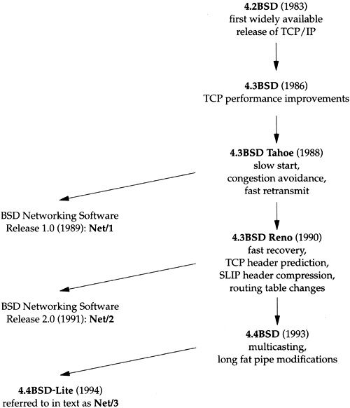
Although the official name of the software described in this text is the 4.4BSD-Lite distribution, we’ll refer to it simply as Net/3.
While the source code is distributed by U. C. Berkeley and is called the Berkeley Software Distribution, the TCP/IP code is really the merger and consolidation of the works of various researchers, both at Berkeley and at other locations.
Throughout the text we’ll use the term Berkeley-derived implementation to refer to vendor implementations such as SunOS 4.x, System V Release 4 (SVR4), and AIX 3.2, whose TCP/IP code was originally developed from the Berkeley sources. These implementations have much in common, often including the same bugs!
Not shown in Figure 1.1 is that the first release with the Berkeley networking code was actually 4.1cBSD in 1982. 4.2BSD, however, was the widely released version in 1983.
BSD releases prior to 4.1cBSD used a TCP/IP implementation developed at Bolt Beranek and Newman (BBN) by Rob Gurwitz and Jack Haverty. Chapter 18 of [Salus 1994] provides additional details on the incorporation of the BBN code into 4.2BSD. Another influence on the Berkeley TCP/IP code was the TCP/IP implementation done by Mike Muuss at the Ballistics Research Lab for the PDP-11.
Limited documentation exists on the changes in the networking code from one release to the next. [Karels and McKusick 1986] describe the changes from 4.2BSD to 4.3BSD, and [Jacobson 1990d] describes the changes from 4.3BSD Tahoe to 4.3BSD Reno.
Two popular application programming interfaces (APIs) for writing programs to use the Internet protocols are sockets and TLI (Transport Layer Interface). The former is sometimes called Berkeley sockets, since it was widely released with the 4.2BSD system (Figure 1.1). It has, however, been ported to many non-BSD Unix systems and many non-Unix systems. The latter, originally developed by AT&T, is sometimes called XTI (X/Open Transport Interface) in recognition of the work done by X/Open, an international group of computer vendors who produce their own set of standards. XTI is effectively a superset of TLI.
This is not a programming text, but we describe the sockets interface since sockets are used by applications to access TCP/IP in Net/3 (and in all other BSD releases). The sockets interface has also been implemented on a wide variety of non-Unix systems. The programming details for both sockets and TLI are available in [Stevens 1990].
System V Release 4 (SVR4) also provides a sockets API for applications to use, although the implementation differs from what we present in this text. Sockets in SVR4 are based on the “streams” subsystem that is described in [Rago 1993].
We’ll use the simple C program shown in Figure 1.2 to introduce many features of the BSD networking implementation in this chapter.
Table 1.2. Example program: send a datagram to the UDP daytime server and read a response.
  1 /*
  2  * Send a UDP datagram to the daytime server on some other host,
  3  * read the reply, and print the time and date on the server.
  4  */

  5 #include    <sys/types.h>
  6 #include    <sys/socket.h>
  7 #include    <netinet/in.h>
  8 #include    <arpa/inet.h>
  9 #include    <stdio.h>
 10 #include    <stdlib.h>
 11 #include    <string.h>

 12 #define BUFFSIZE    150         /* arbitrary size */

 13 int
 14 main()
 15 {
 16     struct sockaddr_in serv;
 17     char    buff[BUFFSIZE];
 18     int     sockfd, n;

 19     if ((sockfd = socket(PF_INET, SOCK_DGRAM, 0)) < 0)
 20         err_sys("socket error");

 21     bzero((char *) &serv, sizeof(serv));
 22     serv.sin_family = AF_INET;
 23     serv.sin_addr.s_addr = inet_addr("140.252.1.32");
 24     serv.sin_port = htons(13);

 25     if (sendto(sockfd, buff, BUFFSIZE, 0,
 26                (struct sockaddr *) &serv, sizeof(serv)) != BUFFSIZE)
 27         err_sys("sendto error");

 28     if ((n = recvfrom(sockfd, buff, BUFFSIZE, 0,
 29                       (struct sockaddr *) NULL, (int *) NULL)) < 2)
 30         err_sys("recvfrom error");
 31     buff[n - 2] = 0;            /* null terminate */
 32     printf("%s
", buff);

 33     exit(0);
34 } |
19-20
socket creates a UDP socket and returns a descriptor to the process, which is stored in the variable sockfd. The error-handling function err_sys is shown in Appendix B.2 of [Stevens 1992]. It accepts any number of arguments, formats them using vsprintf, prints the Unix error message corresponding to the errno value from the system call, and then terminates the process.
We’ve now used the term socket in three different ways. (1) The API developed for 4.2BSD to allow programs to access the networking protocols is normally called the sockets API or just the sockets interface. (2)
socketis the name of a function in the sockets API. (3) We refer to the end point created by the call tosocketas a socket, as in the comment “Create a datagram socket.”Unfortunately, there are still more uses of the term socket. (4) The return value from the
socketfunction is called a socket descriptor or just a socket. (5) The Berkeley implementation of the networking protocols within the kernel is called the sockets implementation, compared to the System V streams implementation, for example. (6) The combination of an IP address and a port number is often called a socket, and a pair of IP addresses and port numbers is called a socket pair. Fortunately, it is usually obvious from the discussion what the term socket refers to.
21-24
An Internet socket address structure (sockaddr_in) is filled in with the IP address (140.252.1.32) and port number (13) of the daytime server. Port number 13 is the standard Internet daytime server, provided by most TCP/IP implementations [Stevens 1994, Fig. 1.9]. Our choice of the server host is arbitrary—we just picked a local host (Figure 1.17) that provides the service.
The function inet_addr takes an ASCII character string representing a dotted-decimal IP address and converts it into a 32-bit binary integer in the network byte order. (The network byte order for the Internet protocol suite is big endian. [Stevens 1990, Chap. 4] discusses host and network byte order, and little versus big endian.) The function htons takes a short integer in the host byte order (which could be little endian or big endian) and converts it into the network byte order (big endian). On a system such as a Sparc, which uses big endian format for integers, htons is typically a macro that does nothing. In BSD/386, however, on the little endian 80386, htons can be either a macro or a function that swaps the 2 bytes in a 16-bit integer.
25-27
The program then calls sendto, which sends a 150-byte datagram to the server. The contents of the 150-byte buffer are indeterminate since it is an uninitialized array allocated on the run-time stack, but that’s OK for this example because the server never looks at the contents of the datagram that it receives. When the server receives a datagram it sends a reply to the client. The reply contains the current time and date on the server in a human-readable format.
Our choice of 150 bytes for the client’s datagram is arbitrary. We purposely pick a value greater than 100 and less than 208 to show the use of an mbuf chain later in this chapter. We also want a value less than 1472 to avoid fragmentation on an Ethernet.
28-32
The program reads the datagram that the server sends back by calling recvfrom. Unix servers typically send back a 26-byte string of the form
Sat Dec 11 11:28:05 1993er
where er is an ASCII carriage return and en is an ASCII linefeed. Our program overwrites the carriage return with a null byte and calls printf to output the result.
We go into lots of detail about various parts of this example in this and later chapters as we examine the implementation of the functions socket, sendto, and recvfrom.
All operating systems provide service points through which programs request services from the kernel. All variants of Unix provide a well-defined, limited number of kernel entry points known as system calls. We cannot change the system calls unless we have the kernel source code. Unix Version 7 provided about 50 system calls, 4.4BSD provides about 135, and SVR4 has around 120.
The system call interface is documented in Section 2 of the Unix Programmer’s Manual. Its definition is in the C language, regardless of how system calls are invoked on any given system.
The Unix technique is for each system call to have a function of the same name in the standard C library. An application calls this function, using the standard C calling sequence. This function then invokes the appropriate kernel service, using whatever technique is required on the system. For example, the function may put one or more of the C arguments into general registers and then execute some machine instruction that generates a software interrupt into the kernel. For our purposes, we can consider the system calls to be C functions.
Section 3 of the Unix Programmer’s Manual defines the general purpose functions available to programmers. These functions are not entry points into the kernel, although they may invoke one or more of the kernel’s system calls. For example, the printf function may invoke the write system call to perform the output, but the functions strcpy (copy a string) and atoi (convert ASCII to integer) don’t involve the operating system at all.
From an implementor’s point of view, the distinction between a system call and a library function is fundamental. From a user’s perspective, however, the difference is not as critical. For example, if we run Figure 1.2 under 4.4BSD, when the program calls the three functions socket, sendto, and recvfrom, each ends up calling a function of the same name within the kernel. We show the BSD kernel implementation of these three system calls later in the text.
If we run the program under SVR4, where the socket functions are in a user library that calls the “streams” subsystem, the interaction of these three functions with the kernel is completely different. Under SVR4 the call to socket ends up invoking the kernel’s open system call for the file /dev/udp and then pushes the streams module sockmod onto the resulting stream. The call to sendto results in a putmsg system call, and the call to recvfrom results in a getmsg system call. These SVR4 details are not critical in this text. We want to point out only that the implementation can be totally different while providing the same API to the application.
This difference in implementation technique also accounts for the manual page for the socket function appearing in Section 2 of the 4.4BSD manual but in Section 3n (the letter n stands for the networking subsection of Section 3) of the SVR4 manuals.
Finally, the implementation technique can change from one release to the next. For example, in Net/1 send and sendto were implemented as separate system calls within the kernel. In Net/3, however, send is a library function that calls sendto, which is a system call:
send(int s, char *msg, int len, int flags)
{
    return(sendto(s, msg, len, flags, (struct sockaddr *) NULL, 0));
}
The advantage in implementing send as a library function that just calls sendto is a reduction in the number of system calls and in the amount of code within the kernel. The disadvantage is the additional overhead of one more function call for the process that calls send.
Since this text describes the Berkeley implementation of TCP/IP, most of the functions called by the process socket, (bind, connect, etc.) are implemented directly in the kernel as system calls.
Net/3 provides a general purpose infrastructure capable of simultaneously supporting multiple communication protocols. Indeed, 4.4BSD supports four distinct communication protocol families:
TCP/IP (the Internet protocol suite), the topic of this book.
XNS (Xerox Network Systems), a protocol suite that is similar to TCP/IP; it was popular in the mid-1980s for connecting Xerox hardware (such as printers and file servers), often using an Ethernet. Although the code is still distributed with Net/3, few people use this protocol suite today, and many vendors who use the Berkeley TCP/IP code remove the XNS code (so they don’t have to support it).
The OSI protocols [Rose 1990; Piscitello and Chapin 1993]. These protocols were designed during the 1980s as the ultimate in open-systems technology, to replace all other communication protocols. Their appeal waned during the early 1990s, and as of this writing their use in real networks is minimal. Their place in history is still to be determined.
The Unix domain protocols. These do not form a true protocol suite in the sense of communication protocols used to exchange information between different systems, but are provided as a form of interprocess communication (IPC).
The advantage in using the Unix domain protocols for IPC between two processes on the same host, versus other forms of IPC such as System V message queues [Stevens 1990], is that the Unix domain protocols are accessed using the same API (sockets) as are the other three communication protocols. Message queues, on the other hand, and most other forms of IPC, have an API that is completely different from both sockets and TLI. Having IPC between two processes on the same host use the networking API makes it easy to migrate a client-server application from one host to many hosts. Two different protocols are provided in the Unix domain—a reliable, connection-oriented, byte-stream protocol that looks like TCP, and an unreliable, connectionless, datagram protocol that looks like UDP.
Although the Unix domain protocols can be used as a form of IPC between two processes on the same host, these processes could also use TCP/IP to communicate with each other. There is no requirement that processes communicating using the Internet protocols reside on different hosts.
The networking code in the kernel is organized into three layers, as shown in Figure 1.3. On the right side of this figure we note where the seven layers of the OSI reference model [Piscitello and Chapin 1993] fit in the BSD organization.
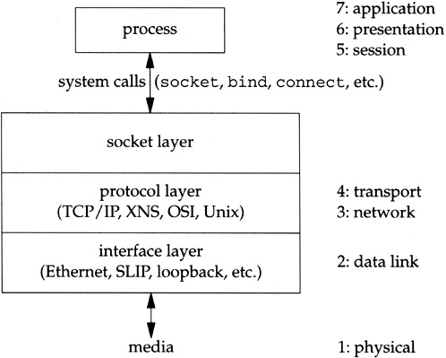
The socket layer is a protocol-independent interface to the protocol-dependent layer below. All system calls start at the protocol-independent socket layer. For example, the protocol-independent code in the socket layer for the
bindsystem call comprises a few dozen lines of code: these verify that the first argument is a valid socket descriptor and that the second argument is a valid pointer in the process. The protocol-dependent code in the layer below is then called, which might comprise hundreds of lines of code.The protocol layer contains the implementation of the four protocol families that we mentioned earlier (TCP/IP, XNS, OSI, and Unix domain). Each protocol suite may have its own internal structure, which we don’t show in Figure 1.3. For example, in the Internet protocol suite, IP is the lowest layer (the network layer) with the two transport layers (TCP and UDP) above IP.
The interface layer contains the device drivers that communicate with the network devices.
Figure 1.2 begins with a call to socket, specifying the type of socket desired. The combination of the Internet protocol family (PF_INET) and a datagram socket (SOCK_DGRAM) gives a socket whose protocol is UDP.
The return value from socket is a descriptor that shares all the properties of other Unix descriptors: read and write can be called for the descriptor, you can dup it, it is shared by the parent and child after a call to fork, its properties can be modified by calling fcntl, it can be closed by calling close, and so on. We see in our example that the socket descriptor is the first argument to both the sendto and recvfrom functions. When our program terminates (by calling exit), all open descriptors including the socket descriptor are closed by the kernel.
We now introduce the data structures that are created by the kernel when the process calls socket. We describe these data structures in more detail in later chapters.
Everything starts with the process table entry for the process. One of these exists for each process during its lifetime.
A descriptor is an index into an array within the process table entry for the process. This array entry points to an open file table structure, which in turn points to an i-node or v-node structure that describes the file. Figure 1.4 summarizes this relationship.
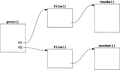
In this figure we also show a descriptor that refers to a socket, which is the focus of this text. We place the notation proc{} above the process table entry, since its definition in C is
struct proc {
    ...
}
and we use this notation for structures in our figures throughout the text.
[Stevens 1992, Sec. 3.10] shows how the relationships between the descriptor, file table structure, and i-node or v-node change as the process calls dup and fork. The relationships between these three data structures exists in all versions of Unix, although the details change with different implementations. Our interest in this text is with the socket structure and the Internet-specific data structures that it points to. But we need to understand how a descriptor leads to a socket structure, since the socket system calls start with a descriptor.
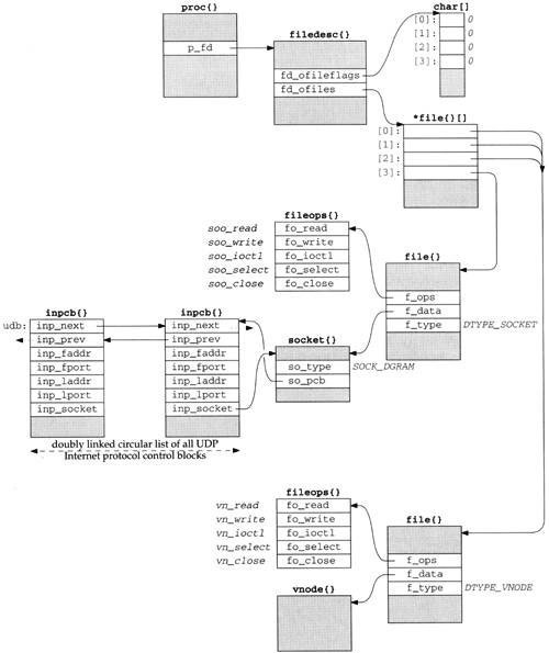
Figure 1.5 shows more details of the Net/3 data structures for our example program, if the program is executed as
a.out
without redirecting standard input (descriptor 0), standard output (descriptor 1), or standard error (descriptor 2). In this example, descriptors 0, 1, and 2 are connected to our terminal, and the lowest-numbered unused descriptor is 3 when socket is called.
When a process executes a system call such as socket, the kernel has access to the process table structure. The entry p_fd in this structure points to the filedesc structure for the process. There are two members of this structure that interest us now: fd_ofileflags is a pointer to an array of characters (the per-descriptor flags for each descriptor), and fd_ofiles is a pointer to an array of pointers to file table structures. The per-descriptor flags are 8 bits wide since only 2 bits can be set for any descriptor: the close-on-exec flag and the mapped-from-device flag. We show all these flags as 0.
We purposely call this section “Descriptors” and not “File Descriptors” since Unix descriptors can refer to lots of things other than files: sockets, pipes, directories, devices, and so on. Nevertheless, much of Unix literature uses the adjective file when talking about descriptors, which is an unnecessary qualification. Here the kernel data structure is called
filedesc{}even though we’re about to describe socket descriptors. We’ll use the unqualified term descriptor whenever possible.
The data structure pointed to by the fd_ofiles entry is shown as *file{}[] since it is an array of pointers to file structures. The index into this array and the array of descriptor flags is the nonnegative descriptor itself: 0, 1, 2, and so on. In Figure 1.5 we show the entries for descriptors 0, 1, and 2 pointing to the same file structure at the bottom of the figure (since all three descriptors refer to our terminal). The entry for descriptor 3 points to a different file structure for our socket descriptor.
The f_type member of the file structure specifies the descriptor type as either DTYPE_SOCKET or DTYPE_VNODE. V-nodes are a general mechanism that allows the kernel to support different types of filesystems—a disk filesystem, a network filesystem (such as NFS), a filesystem on a CD-ROM, a memory-based filesystem, and so on. Our interest in this text is not with v-nodes, since TCP/IP sockets always have a type of DTYPE_SOCKET.
The f_data member of the file structure points to either a socket structure or a vnode structure, depending on the type of descriptor. The f_ops member points to a vector of five function pointers. These function pointers are used by the read, readv, write, writev, ioctl, select, and close system calls, since these system calls work with either a socket descriptor or a nonsocket descriptor. Rather than look at the f_type value each time one of these system calls is invoked and then jump accordingly, the implementors chose always to jump indirectly through the corresponding entry in the fileops structure instead.
Notationally we use a fixed-width font (fo_read) to show the name of a structure member and a slanted fixed-width font (soo_read) to show the contents of a structure member. Also note that sometimes we show the pointer to a structure arriving at the top left corner (e.g., the filedesc structure) and sometimes at the top right corner (e.g., both file structures and both fileops structures). This is to simplify the figures.
Next we come to the socket structure that is pointed to by the file structure when the descriptor type is DTYPE_SOCKET. In our example, the socket type (SOCK_DGRAM for a datagram socket) is stored in the so_type member. An Internet protocol control block (PCB) is also allocated: an inpcb structure. The so_pcb member of the socket structure points to the inpcb, and the inp_socket member of the inpcb structure points to the socket structure. Each points to the other because the activity for a given socket can occur from two directions: “above” or “below.”
When the process executes a system call, such as
sendto, the kernel starts with the descriptor value and usesfd_ofilesto index into the vector offilestructure pointers, ending up with thefilestructure for the descriptor. Thefilestructure points to thesocketstructure, which points to theinpcbstructure.When a UDP datagram arrives on a network interface, the kernel searches through all the UDP protocol control blocks to find the appropriate one, minimally based on the destination UDP port number and perhaps the destination IP address, source IP address, and source port numbers too. Once the
inpcbstructure is located, the kernel finds the correspondingsocketstructure through theinp_socketpointer.
The members inp_faddr and inp_laddr contain the foreign and local IP addresses, and the members inp_fport and inp_lport contain the foreign and local port numbers. The combination of the local IP address and the local port number is often called a socket, as is the combination of the foreign IP address and the foreign port number.
We show another inpcb structure with the name udb on the left in Figure 1.5. This is a global structure that is the head of a linked list of all UDP PCBs. We show the two members inp_next and inp_prev that form a doubly linked circular list of all UDP PCBs. For notational simplicity in the figure, we show two parallel horizontal arrows for the two links instead of trying to have the heads of the arrows going to the top corners of the PCBs. The inp_prev member of the inpcb structure on the right points to the udb structure, not the inp_prev member of that structure. The dotted arrows from udb.inp_prev and the inp_next member of the other PCB indicate that there may be other PCBs on the doubly linked list that we don’t show.
We’ve looked at many kernel data structures in this section, most of which are described further in later chapters. The key points to understand now are:
The call to
socketby our process ends up allocating the lowest unused descriptor (3 in our example). This descriptor is used by the process in all subsequent system calls that refer to this socket.The following kernel structures are allocated and linked together: a
filestructure of typeDTYPE_SOCKET, asocketstructure, and aninpcbstructure. Lots of initialization is performed on these structures that we don’t show: thefilestructure is marked for read and write (since the call tosocketalways returns a descriptor that can be read or written), the default sizes of the input and output buffers are set in thesocketstructure, and so on.We showed nonsocket descriptors for our standard input, output, and error to show that all descriptors end up at a
filestructure, and it is from that point on that differences appear between socket descriptors and other descriptors.
A fundamental concept in the design of the Berkeley networking code is the memory buffer, called an mbuf, used throughout the networking code to hold various pieces of information. Our simple example (Figure 1.2) lets us examine some typical uses of mbufs. In Chapter 2 we describe mbufs in more detail.
In the call to sendto, the fifth argument points to an Internet socket address structure (named serv) and the sixth argument specifies its length (which we’ll see later is 16 bytes). One of the first things done by the socket layer for this system call is to verify that these arguments are valid (i.e., the pointer points to a piece of memory in the address space of the process) and then copy the socket address structure into an mbuf. Figure 1.6 shows the resulting mbuf.
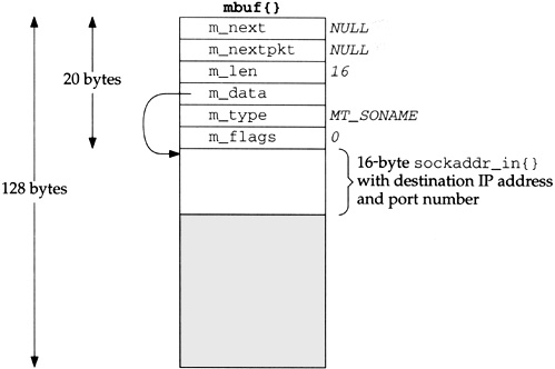
The first 20 bytes of the mbuf is a header containing information about the mbuf. This 20-byte header contains four 4-byte fields and two 2-byte fields. The total size of the mbuf is 128 bytes.
Mbufs can be linked together using the m_next and m_nextpkt members, as we’ll see shortly. Both are null pointers in this example, which is a stand-alone mbuf.
The m_data member points to the data in the mbuf and the m_len member specifies its length. For this example, m_data points to the first byte of data in the mbuf (the byte immediately following the mbuf header). The final 92 bytes of the mbuf data area (108-16) are unused (the shaded portion of Figure 1.6).
The m_type member specifies the type of data contained in the mbuf, which for this example is MT_SONAME (socket name). The final member in the header, m_flags, is zero in this example.
Continuing our example, the socket layer copies the data buffer specified in the call to sendto into one or more mbufs. The second argument to sendto specifies the start of the data buffer (buff), and the third argument is its size in bytes (150). Figure 1.7 shows how two mbufs hold the 150 bytes of data.
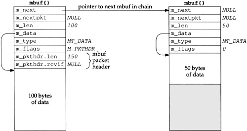
This arrangement is called an mbuf chain. The m_next member in each mbuf links together all the mbufs in a chain.
The next change we see is the addition of two members, m_pkthdr.len and m_pkthdr.rcvif, to the mbuf header in the first mbuf of the chain. These two members comprise the packet header and are used only in the first mbuf of a chain. The m_flags member contains the value M_PKTHDR to indicate that this mbuf contains a packet header. The len member of the packet header structure contains the total length of the mbuf chain (150 in this example), and the next member, rcvif, we’ll see later contains a pointer to the received interface structure for received packets.
Since mbufs are always 128 bytes, providing 100 bytes of data storage in the first mbuf on the chain and 108 bytes of storage in all subsequent mbufs on the chain, two mbufs are needed to store 150 bytes of data. We’ll see later that when the amount of data exceeds 208 bytes, instead of using three or more mbufs, a different technique is used—a larger buffer, typically 1024 or 2048 bytes, called a cluster is used.
One reason for maintaining a packet header with the total length in the first mbuf on the chain is to avoid having to go through all the mbufs on the chain to sum their m_len members when the total length is needed.
After the socket layer copies the destination socket address structure into an mbuf (Figure 1.6) and the data into an mbuf chain (Figure 1.7), the protocol layer corresponding to the socket descriptor (a UDP socket) is called. Specifically, the UDP output routine is called and pointers to the mbufs that we’ve examined are passed as arguments. This routine needs to prepend an IP header and a UDP header in front of the 150 bytes of data, fill in the headers, and pass the mbufs to the IP output routine.
The way that data is prepended to the mbuf chain in Figure 1.7 is to allocate another mbuf, make it the front of the chain, and copy the packet header from the mbuf with 100 bytes of data into the new mbuf. This gives us the three mbufs shown in Figure 1.8.
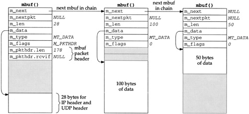
The IP header and UDP header are stored at the end of the new mbuf that becomes the head of the chain. This allows for any lower-layer protocols (e.g., the interface layer) to prepend its headers in front of the IP header if necessary, without having to copy the IP and UDP headers. The m_data pointer in the first mbuf points to the start of these two headers, and m_len is 28. Future headers that fit in the 72 bytes of unused space between the packet header and the IP header can be prepended before the IP header by adjusting the m_data pointer and the m_len accordingly. Shortly we’ll see that the Ethernet header is built here in this fashion.
Notice that the packet header has been moved from the mbuf with 100 bytes of data into the new mbuf. The packet header must always be in the first mbuf on the chain. To accommodate this movement of the packet header, the M_PKTHDR flag is set in the first mbuf and cleared in the second mbuf. The space previously occupied by the packet header in the second mbuf is now unused. Finally, the length member in the packet header is incremented by 28 bytes to become 178.
The UDP output routine then fills in the UDP header and as much of the IP header as it can. For example, the destination address in the IP header can be set, but the IP checksum will be left for the IP output routine to calculate and store.
The UDP checksum is calculated and stored in the UDP header. Notice that this requires a complete pass of the 150 bytes of data stored in the mbuf chain. So far the kernel has made two complete passes of the 150 bytes of user data: once to copy the data from the user’s buffer into the kernel’s mbufs, and now to calculate the UDP checksum. Extra passes over the data can degrade the protocol’s performance, and in later chapters we describe alternative implementation techniques that avoid unnecessary passes.
At this point the UDP output routine calls the IP output routine, passing a pointer to the mbuf chain for IP to output.
The IP output routine fills in the remaining fields in the IP header including the IP checksum, determines the outgoing interface to which the datagram should be given (this is the IP routing function), fragments the IP datagram if necessary, and calls the interface output function.
Assuming the outgoing interface is an Ethernet, a general-purpose Ethernet output function is called, again with a pointer to the mbuf chain as an argument.
The first function of the Ethernet output function is to convert the 32-bit IP address into its corresponding 48-bit Ethernet address. This is done using ARP (Address Resolution Protocol) and may involve sending an ARP request on the Ethernet and waiting for an ARP reply. While this takes place, the mbuf chain to be output is held, waiting for the reply.
The Ethernet output routine then prepends a 14-byte Ethernet header to the first mbuf in the chain, immediately before the IP header (Figure 1.8). This contains the 6-byte Ethernet destination address, 6-byte Ethernet source address, and 2-byte Ethernet frame type.
The mbuf chain is then added to the end of the output queue for the interface. If the interface is not currently busy, the interface’s “start output” routine is called directly. If the interface is busy, its output routine will process the new mbuf on its queue when it is finished with the buffers already on its output queue.
When the interface processes an mbuf that’s on its output queue, it copies the data to its transmit buffer and initiates the output. In our example, 192 bytes are copied to the transmit buffer: the 14-byte Ethernet header, 20-byte IP header, 8-byte UDP header, and 150 bytes of user data. This is the third complete pass of the data by the kernel. Once the data is copied from the mbuf chain into the device’s transmit buffer, the mbuf chain is released by the Ethernet device driver. The three mbufs are put back into the kernel’s pool of free mbufs.
In Figure 1.9 we give an overview of the processing that takes place when a process calls sendto to transmit a single UDP datagram. The relationship of the processing that we’ve described to the three layers of kernel code (Figure 1.3) is also shown.
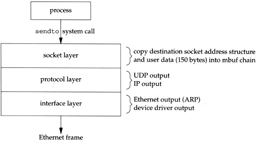
Function calls pass control from the socket layer to the UDP output routine, to the IP output routine, and then to the Ethernet output routine. Each function call passes a pointer to the mbuf chain to be output. At the lowest layer, the device driver, the mbuf chain is placed on the device’s output queue and the device is started, if necessary. The function calls return in reverse order of their call, and eventually the system call returns to the process. Notice that there is no queueing of the UDP data until it arrives at the device driver. The higher layers just prepend their header and pass the mbuf to the next lower layer.
At this point our program calls recvfrom to read the server’s reply. Since the input queue for the specified socket is empty (assuming the reply has not been received yet), the process is put to sleep.
Input processing is different from the output processing just described because the input is asynchronous. That is, the reception of an input packet is triggered by a receive-complete interrupt to the Ethernet device driver, not by a system call issued by the process. The kernel handles this device interrupt and schedules the device driver to run.
The Ethernet device driver processes the interrupt and, assuming it signifies a normal receive-complete condition, the data bytes are read from the device into an mbuf chain. In our example, 54 bytes of data are received and copied into a single mbuf: the 20-byte IP header, 8-byte UDP header, and 26 bytes of data (the time and date on the server). Figure 1.10 shows the format of this mbuf.
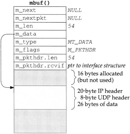
This mbuf is a packet header (the M_PKTHDR flag is set in m_flags) since it is the first mbuf of a data record. The len member in the packet header contains the total length of data and the rcvif. member contains a pointer to the interface structure corresponding to the received interface (Chapter 3). We see that the rcvif member is used for received packets but not for output packets (Figures 1.7 and 1.8).
The first 16 bytes of the data portion of the mbuf are allocated for an interface layer header, but are not used. Since the amount of data (54 bytes) fits in the remaining 84 bytes of the mbuf, the data is stored in the mbuf itself.
The device driver passes the mbuf to a general Ethernet input routine which looks at the type field in the Ethernet frame to determine which protocol layer should receive the packet. In this example, the type field will specify an IP datagram, causing the mbuf to be added to the IP input queue. Additionally, a software interrupt is scheduled to cause the IP input process routine to be executed. The device’s interrupt handling is then complete.
IP input is asynchronous and is scheduled to run by a software interrupt. The software interrupt is set by the interface layer when it receives an IP datagram on one of the system’s interfaces. When the IP input routine executes it loops, processing each IP datagram on its input queue and returning when the entire queue has been processed.
The IP input routine processes each IP datagram that it receives. It verifies the IP header checksum, processes any IP options, verifies that the datagram was delivered to the right host (by comparing the destination IP address of the datagram with the host’s IP addresses), and forwards the datagram if the system was configured as a router and the datagram is destined for some other IP address. If the IP datagram has reached its final destination, the protocol field in the IP header specifies which protocol’s input routine is called: ICMP, IGMP, TCP, or UDP. In our example, the UDP input routine is called to process the UDP datagram.
The UDP input routine verifies the fields in the UDP header (the length and optional checksum) and then determines whether or not a process should receive the datagram. In Chapter 23 we discuss exactly how this test is made. A process can receive all datagrams destined to a specified UDP port, or the process can tell the kernel to restrict the datagrams it receives based on the source and destination IP addresses and source and destination port numbers.
In our example, the UDP input routine starts at the global variable udb (Figure 1.5) and goes through the linked list of UDP protocol control blocks, looking for one with a local port number (inp_lport) that matches the destination port number of the received UDP datagram. This will be the PCB created by our call to socket, and the inp_socket member of this PCB points to the corresponding socket structure, allowing the received data to be queued for the correct socket.
In our example program we never specify the local port number for our application. We’ll see in Exercise 23.3 that a side effect of writing the first UDP datagram to a socket that has not yet bound a local port number is the automatic assignment by the kernel of a local port number (termed an ephemeral port) to that socket. That’s how the
inp_lportmember of the PCB for our socket gets set to some nonzero value.
Since this UDP datagram is to be delivered to our process, the sender’s IP address and UDP port number are placed into an mbuf, and this mbuf and the data (26 bytes in our example) are appended to the receive queue for the socket. Figure 1.11 shows the two mbufs that are appended to the socket’s receive queue.
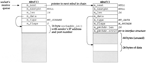
Comparing the second mbuf on this chain (the one of type MT_DATA) with the mbuf in Figure 1.10, the m_len and m_pkthdr.len members have both been decremented by 28 (20 bytes for the IP header and 8 for the UDP header) and the m_data pointer has been incremented by 28. This effectively removes the IP and UDP headers, leaving only the 26 bytes of data to be appended to the socket’s receive queue.
The first mbuf in the chain contains a 16-byte Internet socket address structure with the sender’s IP address and UDP port number. Its type is MT_SONAME, similar to the mbuf in Figure 1.6. This mbuf is created by the socket layer to return this information to the calling process through the recvfrom or recvmsg system calls. Even though there is room (16 bytes) in the second mbuf on this chain for this socket address structure, it must be stored in its own mbuf since it has a different type (MT_SONAME versus MT_DATA).
The receiving process is then awakened. If the process is asleep waiting for data to arrive (which is the scenario in our example), the process is marked as run-able for the kernel to schedule. A process can also be notified of the arrival of data on a socket by the select system call or with the SIGIO signal.
Our process has been asleep in the kernel, blocked in its call to recvfrom, and the process now wakes up. The 26 bytes of data appended to the socket’s receive queue by the UDP layer (the received datagram) are copied by the kernel from the mbuf into our program’s buffer.
Notice that our program sets the fifth and sixth arguments to recvfrom to null pointers, telling the system call that we’re not interested in receiving the sender’s IP address and UDP port number. This causes the recvfrom system call to skip the first mbuf in the chain (Figure 1.11), returning only the 26 bytes of data in the second mbuf. The kernel’s recvfrom code then releases the two mbufs in Figure 1.11 and returns them to its pool of free mbufs.
Figure 1.12 summarizes the communication that takes place between the layers for both network output and network input. It repeats Figure 1.3 considering only the Internet protocols and emphasizing the communications between the layers.
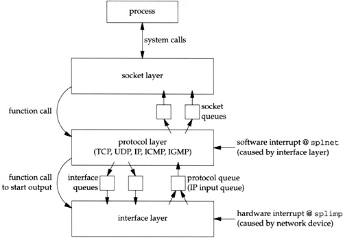
The notations splnet and splimp are discussed in the next section.
We use the plural terms socket queues and interface queues since there is one queue per socket and one queue per interface (Ethernet, loopback, SLIP, PPP, etc.), but we use the singular term protocol queue because there is a single IP input queue. If we considered other protocol layers, we would have one input queue for the XNS protocols and one for the OSI protocols.
We saw in Section 1.10 that the processing of input packets by the networking code is asynchronous and interrupt driven. First, a device interrupt causes the interface layer code to execute, which posts a software interrupt that later causes the protocol layer code to execute. When the kernel is finished with these interrupt levels the socket code will execute.
There is a priority level assigned to each hardware and software interrupt. Figure 1.13 shows the normal ordering of the eight priority levels, from the lowest (no interrupts blocked) to the highest (all interrupts blocked).
Table 1.13. Kernel functions that block selected interrupts.
Function | Description | |
|---|---|---|
| normal operating mode, nothing blocked | (lowest priority) |
| low-priority clock processing | |
| network protocol processing | |
| terminal I/O | |
| disk and tape I/O | |
| network device I/O | |
| high-priority clock processing | |
| all interrupts blocked | (highest priority) |
| (see text) | |
Table 4.5 of [Leffler et al. 1989] shows the priority levels used in the VAX implementation. The Net/3 implementation for the 386 uses the eight functions shown in Figure 1.13, but
splsoftclockandsplnetare at the same level, andsplclockandsplhighare also at the same level.The name imp that is used for the network interface level comes from the acronym IMP (Interface Message Processor), which was the original type of router used on the ARPANET.
The ordering of the different priority levels means that a higher-priority interrupt can preempt a lower-priority interrupt. Consider the sequence of events depicted in Figure 1.14.
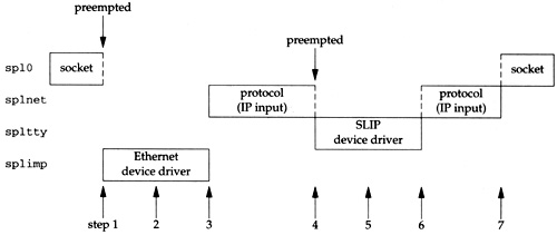
While the socket layer is executing at
spl0, an Ethernet device driver interrupt occurs, causing the interface layer to execute atsplimp. This interrupt preempts the socket layer code. This is the asynchronous execution of the interface input routine.While the Ethernet device driver is running, it places a received packet onto the IP input queue and schedules a software interrupt to occur at
splnet. The software interrupt won’t take effect immediately since the kernel is currently running at a higher priority level (splimp).When the Ethernet device driver completes, the protocol layer executes at
splnet. This is the asynchronous execution of the IP input routine.A terminal device interrupt occurs (say the completion of a SLIP packet) and it is handled immediately, preempting the protocol layer, since terminal I/O (
spltty) is a higher priority than the protocol layer (splnet) in Figure 1.13. This is the asynchronous execution of the interface input routine.The SLIP driver places the received packet onto the IP input queue and schedules another software interrupt for the protocol layer.
When the SLIP driver completes, the preempted protocol layer continues at
splnet, finishes processing the packet received from the Ethernet device driver, and then processes the packet received from the SLIP driver. Only when there are no more input packets to process will it return control to whatever it preempted (the socket layer in this example).The socket layer continues from where it was preempted.
One concern with these different priority levels is how to handle data structures shared between the different levels. Examples of shared data structures are the three we show between the different levels in Figure 1.12—the socket, interface, and protocol queues. For example, while the IP input routine is taking a received packet off its input queue, a device interrupt can occur, preempting the protocol layer, and that device driver can add another packet to the IP input queue. These shared data structures (the IP input queue in this example, which is shared between the protocol layer and the interface layer) can be corrupted if nothing is done to coordinate the shared access.
The Net/3 code is sprinkled with calls to the functions splimp and splnet. These two calls are always paired with a call to splx to return the processor to the previous level. For example, here is the code executed by the IP input function at the protocol layer to check if there is another packet on its input queue to process:
struct mbuf *m;
int s;

s = splimp();
IF_DEQUEUE(&ipintrq, m);
splx(s);

if (m == 0)
    return;
The call to splimp raises the CPU priority to the level used by the network device drivers, preventing any network device driver interrupt from occurring. The previous priority level is returned as the value of the function and stored in the variable s. Then the macro IF_DEQUEUE is executed to remove the next packet at the head of the IP input queue (ipintrq), placing the pointer to this mbuf chain in the variable m. Finally the CPU priority is returned to whatever it was when splimp was called, by calling splx with an argument of s (the saved value from the earlier call to splimp).
Since all network device driver interrupts are disabled between the calls to splimp and splx, the amount of code between these calls should be minimal. If interrupts are disabled for an extended period of time, additional device interrupts could be ignored, and data might be lost. For this reason the test of the variable m (to see if there is another packet to process) is performed after the call to splx, and not before the call.
The Ethernet output routine needs these spl calls when it places an outgoing packet onto an interface’s queue, tests whether the interface is currently busy, and starts the interface if it was not busy.
struct mbuf *m;
int s;

s = splimp();
/*
 * Queue message on interface, and start output if interface not active.
 */
if (IF_QFULL(&ifp->if_snd)) {
    IF_DROP(&ifp->if_snd);    /* queue is full, drop packet */
    splx(s);
    error = ENOBUFS;
    goto bad;
}

IF_ENQUEUE(&ifp->if_snd, m);  /* add the packet to interface queue */

if ((ifp->if_flags & IFF_OACTIVE) == 0)
    (*ifp->if_start)(ifp);    /* start interface */

 splx(s);
The reason device interrupts are disabled in this example is to prevent the device driver from taking the next packet off its send queue while the protocol layer is adding a packet to that queue. The driver’s send queue is a data structure shared between the protocol layer and the interface layer.
We’ll see calls to the spl functions throughout the source code.
Figure 1.15 shows the organization of the Net/3 networking source tree, assuming it is located in the /usr/src/sys directory.
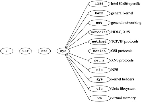
This text focuses on the netinet directory, which contains all the TCP/IP source code. We also look at some files in the kern and net directories. The former contains the protocol-independent socket code, and the latter contains some general networking functions used by the TCP/IP routines, such as the routing code.
Briefly, the files contained in each directory are as follows:
i386:the Intel 80×86-specific directories. For example, the directoryi386/isacontains the device drivers specific to the ISA bus. The directoryi386/standcontains the stand-alone bootstrap code.kern:general kernel files that don’t belong in one of the other directories. For example, the kernel files to handle theforkandexecsystem calls are in this directory. We look at only a few files in this directory—the ones for the socket system calls (the socket layer in Figure 1.3).net:general networking files, for example, general network interface functions, the BPF (BSD Packet Filter) code, the SLIP driver, the loopback driver, and the routing code. We look at some of the files in this directory.netccitt:interface code for the OSI protocols, including the HDLC (high-level data-link control) and X.25 drivers.netinet:the code for the Internet protocols: IP, ICMP, IGMP, TCP, and UDP. This text focuses on the files in this directory.netiso:the OSI protocols.netns:the Xerox XNS protocols.nfs:code for Sun’s Network File System.sys:system headers. We look at several headers in this directory. The files in this directory also appear in the directory/usr/include/sys.ufs:code for the Unix filesystem, sometimes called the Berkeley fast filesystem. This is the normal disk-based filesystem.vm:code for the virtual memory system.
Figure 1.16 gives another view of the source code organization, this time mapped to our three kernel layers. We ignore directories such as netimp and nfs that we don’t consider in this text.
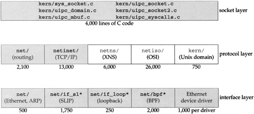
The numbers below each box are the approximate number of lines of C code for that feature, which includes all comments in the source files.
We don’t look at all the source code shown in this figure. The netns and netiso directories are shown for comparison against the Internet protocols. We only consider the shaded boxes.
Figure 1.17 shows the test network that is used for all the examples in the text. Other than the host vangogh at the top of the figure, all the IP addresses belong to the class B network ID 140.252, and all the hostnames belong to the .tuc.noao.edu domain. (noao stands for “National Optical Astronomy Observatories” and tuc stands for Tucson.) For example, the system in the lower right has a complete hostname of svr4.tuc.noao.edu and an IP address of 140.252.13.34. The notation at the top of each box is the operating system running on that system.
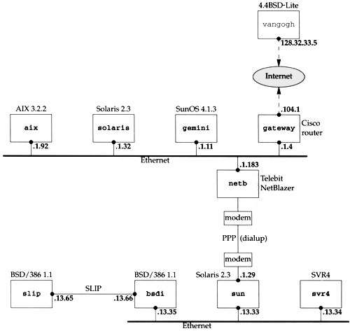
The host at the top has a complete name of vangogh.cs.berkeley.edu and is reachable from the other hosts across the Internet.
This figure is nearly identical to the test network used in Volume 1, although some of the operating systems have been upgraded and the dialup link between sun and netb now uses PPP instead of SLIP. Additionally, we have replaced the Net/2 networking code provided with BSD/386 V1.1 with the Net/3 networking code.
This chapter provided an overview of the Net/3 networking code. Using a simple program (Figure 1.2) that sends a UDP datagram to a daytime server and receives a reply, we’ve followed the resulting output and input through the kernel. Mbufs hold the information being output and the received IP datagrams. The next chapter examines mbufs in more detail.
UDP output occurs when the process executes the sendto system call, while IP input is asynchronous. When an IP datagram is received by a device driver, the datagram is placed onto IP’s input queue and a software interrupt is scheduled to cause the IP input function to execute. We reviewed the different interrupt levels used by the networking code within the kernel. Since many of the networking data structures are shared by different layers that can execute at different interrupt priorities, the code must be careful when accessing or modifying these shared structures. We’ll encounter calls to the spl functions in almost every function that we look at.
The chapter finishes with a look at the overall organization of the source code in Net/3, focusing on the code that this text examines.
1.1 | Type in the example program (Figure 1.2) and run it on your system. If your system has a system call tracing capability, such as |
1.2 | In our example that calls |
1.2 | SLIP drivers execute at |