
Networking protocols place many demands on the memory management facilities of the kernel. These demands include easily manipulating buffers of varying sizes, prepending and appending data to the buffers as the lower layers encapsulate data from higher layers, removing data from buffers (as headers are removed as data packets are passed up the protocol stack), and minimizing the amount of data copied for all these operations. The performance of the networking protocols is directly related to the memory management scheme used within the kernel.
In Chapter 1 we introduced the memory buffer used throughout the Net/3 kernel: the mbuf, which is an abbreviation for “memory buffer.” In this chapter we look in more detail at mbufs and at the functions within the kernel that are used to manipulate them, as we will encounter mbufs on almost every page of the text. Understanding mbufs is essential for understanding the rest of the text.
The main use of mbufs is to hold the user data that travels from the process to the network interface, and vice versa. But mbufs are also used to contain a variety of other miscellaneous data: source and destination addresses, socket options, and so on.
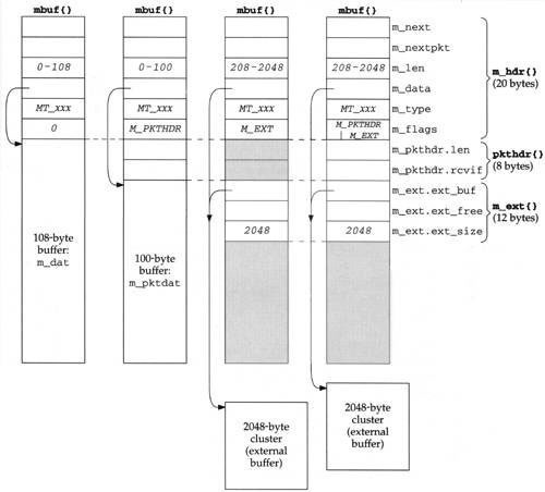
Figure 2.1 shows the four different kinds of mbufs that we’ll encounter, depending on the M_PKTHDR and M_EXT flags in the m_flags member. The differences between the four mbufs in Figure 2.1, from left to right, are as follows:
If
m_flagsequals 0, the mbuf contains only data. There is room in the mbuf for up to 108 bytes of data (them_datarray). Them_datapointer points somewhere in this 108-byte buffer. We show it pointing to the start of the buffer, but it can point anywhere in the buffer. Them_lenmember specifies the number of bytes of data, starting atm_data. Figure 1.6 was an example of this type of mbuf.In Figure 2.1 there are six members in the
m_hdrstructure, and its total size is 20 bytes. When we look at the C definition of this structure (Figure 2.8) we’ll see that the first four members occupy 4 bytes each and the last two occupy 2 bytes each. We don’t try to differentiate between the 4-byte members and the 2-byte members in Figure 2.1.The second type of mbuf has an
m_flagsvalue ofM_PKTHDR, specifying a packet header, that is, the first mbuf describing a packet of data. The data is still contained within the mbuf itself, but because of the 8 bytes taken by the packet header, only 100 bytes of data fit within this mbuf (in them_pktdatarray). Figure 1.10 was an example of this type of mbuf.The
m_pkthdr.lenvalue is the total length of all the data in the chain mbuf for this packet: the sum of them_lenvalues for all the mbufs linked through them_nextpointer, as shown in Figure 1.8. Them_pkthdr.rcvifmember is not used for output packets, but for received packets contains a pointer to the received interface’sifnetstructure (Figure 3.6).The next type of mbuf does not contain a packet header (
M_PKTHDRis not set) but contains more than 208 bytes of data, so an external buffer called a cluster is used (M_EXTis set). Room is still allocated in the mbuf itself for the packet header structure, but it is unused—we show it shaded in Figure 2.1. Instead of using multiple mbufs to contain the data (the first with 100 bytes of data, and all the rest with 108 bytes of data each), Net/3 allocates a cluster of size 1024 or 2048 bytes. Them_datapointer in the mbuf points somewhere inside this cluster.The Net/3 release supports seven different architectures. Four define the size of a cluster as 1024 bytes (the traditional value) and three define it as 2048. The reason 1024 has been used historically is to save memory: if the cluster size is 2048, about one-quarter of each cluster is unused for Ethernet packets (1500 bytes maximum). We’ll see in Section 27.5 that the Net/3 TCP never sends more than the cluster size per TCP segment, so with a cluster size of 1024, almost one-third of each 1500-byte Ethernet frame is unused. But [Mogul 1993, Figure 15.15] shows that a sizable performance improvement occurs on an Ethernet when maximum-sized frames are sent instead of 1024-byte frames. This is a performance-versus-memory tradeoff. Older systems used 1024-byte clusters to save memory while newer systems with cheaper memory use 2048 to increase performance. Throughout this text we assume a cluster size of 2048.
Unfortunately different names have been used for what we call clusters. The constant
MCLBYTESis the size of these buffers (1024 or 2048) and the names of the macros to manipulate these buffers areMCLGET, MCLALLOC, andMCLFREE. This is why we call them clusters. But we also see that the mbuf flag isM_EXT, which stands for “external” buffer. Finally, [Leffler et al. 1989] calls them mapped pages. This latter name refers to their implementation, and we’ll see in Section 2.9 that clusters can be shared when a copy is required.We would expect the minimum value of
m_lento be 209 for this type of mbuf, not 208 as we indicate in the figure. That is, a record with 208 bytes of data can be stored in two mbufs, with 100 bytes in the first and 108 in the second. The source code, however, has a bug and allocates a cluster if the size is greater than or equal to 208.The final type of mbuf contains a packet header and contains more than 208 bytes of data. Both
M_PKTHDRandM_EXTare set.
There are numerous additional points we need to make about Figure 2.1:
The size of the
mbufstructure is always 128 bytes. This means the amount of unused space following them_extstructure in the two mbufs on the right in Figure 2.1 is 88 bytes (128 – 20 – 8 –12).A data buffer with an
m_lenof 0 bytes is OK since some protocols (e.g., UDP) allow 0-length records.In each of the mbufs we show the
m_datamember pointing to the beginning of the corresponding buffer (either the mbuf buffer itself or a cluster). This pointer can point anywhere in the corresponding buffer, not necessarily the front.Mbufs with a cluster always contain the starting address of the buffer (
m_ext.ext_buf) and its size (m_ext.ext_size). We assume a size of 2048 throughout this text. Them_dataandm_ext. ext_bufmembers are not the same (as we show) unlessm_dataalso points to the first byte of the buffer. The third member of them_extstructure,ext_free, is not currently used by Net/3.The
m_nextpointer links together the mbufs forming a single packet (record) into an mbuf chain, as in Figure 1.8.The
m_nextpktpointer links multiple packets (records) together to form a queue of mbufs. Each packet on the queue can be a single mbuf or an mbuf chain. The first mbuf of each packet contains a packet header. If multiple mbufs define a packet, them_nextpktmember of the first mbuf is the only one used—them_nextpktmember of the remaining mbufs on the chain are all null pointers.
Figure 2.2 shows an example of two packets on a queue. It is a modification of Figure 1.8. We have placed the UDP datagram onto the interface output queue (showing that the 14-byte Ethernet header has been prepended to the IP header in the first mbuf on the chain) and have added a second packet to the queue: a TCP segment containing 1460 bytes of user data. The TCP data is contained in a cluster and an mbuf has been prepended to contain its Ethernet, IP, and TCP headers. With the cluster we show that the data pointer into the cluster (m_data) need not point to the front of the cluster. We show that the queue has a head pointer and a tail pointer. This is how the interface output queues are handled in Net/3. We have also added the m_ext structure to the mbuf with the M_EXT flag set and have shaded in the unused pkthdr structure of this mbuf.
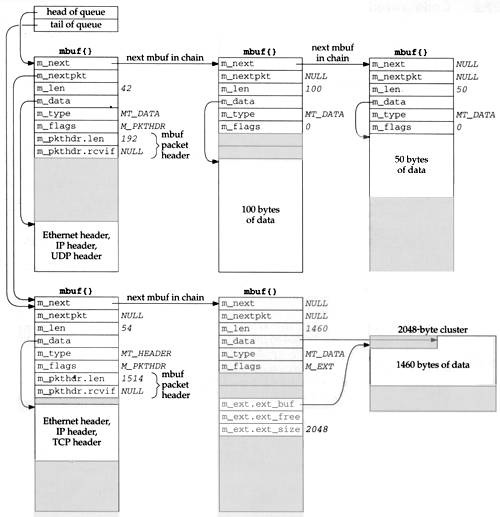
The first mbuf with the packet header for the UDP datagram has a type of MT_DATA, but the first mbuf with the packet header for the TCP segment has a type of MT_HEADER. This is a side effect of the different way UDP and TCP prepend the headers to their data, and makes no difference. Mbufs of these two types are essentially the same. It is the m_flags value of M_PKTHDR in the first mbuf on the chain that indicates a packet header.
Careful readers may note a difference between our picture of an mbuf (the Net/3 mbuf, Figure 2.1) and the picture in [Leffler et al. 1989, p. 290], a Net/1 mbuf. The changes were made in Net/2: adding the m_flags member, renaming the m_act pointer to be m_nextpkt, and moving this pointer to the front of the mbuf.
The difference in the placement of the protocol headers in the first mbuf for the UDP and TCP examples is caused by UDP calling M_PREPEND (Figure 23.15 and Exercise 23.1) while TCP calls MGETHDR (Figure 26.25).
The mbuf functions are in a single C file and the mbuf macros and various mbuf definitions are in a single header, as shown in Figure 2.3.
One global variable is introduced in this chapter, shown in Figure 2.4.
Table 2.4. Global variables introduced in this chapter.
Variable | Datatype | Description |
|---|---|---|
|
|
|
Various statistics are maintained in the global structure mbstat, described in Figure 2.5.
Table 2.5. Mbuf statistics maintained in the mbstat structure.
| Description |
|---|---|
| #free clusters |
| #clusters obtained from page pool |
| #times protocol’s drain functions called to reclaim space |
| #times failed to find space (not used) |
| #mbufs obtained from page pool (not used) |
| counter of current mbuf allocations: |
| spare field (not used) |
| #times waited for space (not used) |
This structure can be examined with the netstat -m command; Figure 2.6 shows some sample output. The two values printed for the number of mapped pages in use are m_clusters (34) minus m_clfree (32), giving the number of clusters currently in use (2), and m_clusters (34).
Table 2.6. Sample mbuf statistics.
|
|
|---|---|
99 mbufs in use:
        1 mbufs allocated to data
        43 mbufs allocated to packet headers
        17 mbufs allocated to protocol control blocks
        20 mbufs allocated to socket names and addresses
        18 mbufs allocated to socket options
2/34 mapped pages in use
80 Kbytes allocated to network (20% in use)
0 requests for memory denied
0 requests for memory delayed
0 calls to protocol drain routines | m_mtypes[MT_DATA] m_mtypes[MT_HEADER] m_mtypes[MT_PCB] m_mtypes[MT_SONAME] m_mtypes[MT_SOOPTS] (see text) (see text) m_drops m_wait m_drain |
The number of Kbytes of memory allocated to the network is the mbuf memory (99 x 128 bytes) plus the cluster memory (34 x 2048 bytes) divided by 1024. The percentage in use is the mbuf memory (99 x 128 bytes) plus the cluster memory in use (2 x 2048 bytes) divided by the total network memory (80 Kbytes), times 100.
The mbuf statistics show a common technique that we see throughout the Net/3 sources. The kernel keeps track of certain statistics in a global variable (the mbstat structure in this example). A process (in this case the netstat program) examines the statistics while the kernel is running.
Rather than provide system calls to fetch the statistics maintained by the kernel, the process obtains the address within the kernel of the data structure in which it is interested by reading the information saved by the link editor when the kernel was built. The process then calls the kvm(3) functions to read the corresponding location in the kernel’s memory by using the special file /dev/mem. If the kernel’s data structure changes from one release to the next, any program that reads that structure must also change.
There are a few constants that we encounter repeatedly when dealing with mbufs. Their values are shown in Figure 2.7. All are defined in mbuf.h except MCLBYTES, which is defined in /usr/include/machine/param.h.
Figure 2.8 shows the definition of the mbuf structure.
Table 2.8. Mbuf structures.
-------------------------------------------------------------------------- mbuf.h 60 /* header at beginning of each mbuf: */ 61 struct m_hdr { 62 struct mbuf *mh_next; /* next buffer in chain */ 63 struct mbuf *mh_nextpkt; /* next chain in queue/record */ 64 int mh_len; /* amount of data in this mbuf */ 65 caddr_t mh_data; /* pointer to data */ 66 short mh_type; /* type of data (Figure 2.10) */ 67 short mh_flags; /* flags (Figure 2.9) */ 68 }; 69 /* record/packet header in first mbuf of chain; valid if M_PKTHDR set */ 70 struct pkthdr { 71 int len; /* total packet length */ 72 struct ifnet *rcvif; /* receive interface */ 73 }; 74 /* description of external storage mapped into mbuf, valid if M_EXT set */ 75 struct m_ext { 76 caddr_t ext_buf; /* start of buffer */ 77 void (*ext_free) (); /* free routine if not the usual */ 78 u_int ext_size; /* size of buffer, for ext_free */ 79 }; 80 struct mbuf { 81 struct m_hdr m_hdr; 82 union { 83 struct { 84 struct pkthdr MH_pkthdr; /* M_PKTHDR set */ 85 union { 86 struct m_ext MH_ext; /* M_EXT set */ 87 char MH_databuf[MHLEN]; 88 } MH_dat; 89 } MH; 90 char M_databuf[MLEN]; /* !M_PKTHDR, !M_EXT */ 91 } M_dat; 92 }; 93 #define m_next m_hdr.mh_next 94 #define m_len m_hdr.mh_len 95 #define m_data m_hdr.mh_data 96 #define m_type m_hdr.mh_type 97 #define m_flags m_hdr.mh_flags 98 #define m_nextpkt m_hdr.mh_nextpkt 99 #define m_act m_nextpkt 100 #define m_pkthdr M_dat.MH.MH_pkthdr 101 #define m_ext M_dat.MH.MH_dat.MH_ext 102 #define m_pktdat M_dat.MH.MH_dat.MH_databuf 103 #define m_dat M_dat.M_databuf -------------------------------------------------------------------------- mbuf.h |
The mbuf structure is defined as an m_hdr structure, followed by a union. As the comments indicate, the contents of the union depend on the flags M_PKTHDR and M_EXT.
93-103
These 11 #define statements simplify access to the members of the structures and unions within the mbuf structure. We will see this technique used throughout the Net/3 sources whenever we encounter a structure containing other structures or unions.
We previously described the purpose of the first two members in the mbuf structure: the m_next pointer links mbufs together into an mbuf chain and the m_nextpkt pointer links mbuf chains together into a queue of mbufs.
Figure 1.8 differentiated between the m_len member of each mbuf and the m_pkthdr.len member in the packet header. The latter is the sum of all the m_len members of all the mbufs on the chain.
There are five independent values for the m_flags member, shown in Figure 2.9.
Table 2.9. m_flags values.
| Description |
|---|---|
| sent/received as link-level broadcast |
| end of record |
| cluster (external buffer) associated with this mbuf |
| sent/received as link-level multicast |
| first mbuf that forms a packet (record) |
|
|
We have already described the M_EXT and M_PKTHDR flags. M_EOR is set in an mbuf containing the end of a record. The Internet protocols (e.g., TCP) never set this flag, since TCP provides a byte-stream service without any record boundaries. The OSI and XNS transport layers, however, do use this flag. We will encounter this flag in the socket layer, since this layer is protocol independent and handles data to and from all the transport layers.
The next two flags, M_BCAST and M_MCAST, are set in an mbuf when the packet will be sent to or was received from a link-layer broadcast address or multicast address. These two constants are flags between the protocol layer and the interface layer (Figure 1.3).
The final value, M_COPYFLAGS, specifies the flags that are copied when an mbuf containing a packet header is copied.
Figure 2.10 shows the MT_xxx constants used in the m_type member to identify the type of data stored in the mbuf. Although we tend to think of an mbuf as containing user data that is sent or received, mbufs can contain a variety of different data structures. Recall in Figure 1.6 that an mbuf was used to hold a socket address structure with the destination address for the sendto system call. Its m_type member was set to MT_SONAME.
Table 2.10. Values for m_type member.
Mbuf | Used in Net/3 TCP/IP code | Description | Memory type |
|---|---|---|---|
| • | extra-data protocol message |
|
| • | dynamic data allocation |
|
| should be on free list |
| |
| • | fragment reassembly header |
|
| • | packet header |
|
| IMP host tables |
| |
| interface address |
| |
| expedited (out-of-band) data |
| |
| protocol control block |
| |
| access rights |
| |
| routing tables |
| |
| • | socket name |
|
| • | socket options |
|
| socket structure |
|
Not all of the mbuf type values in Figure 2.10 are used in Net/3. Some are historical (MT_HTABLE), and others are not used in the TCP/IP code but are used elsewhere in the kernel. For example, MT_OOBDATA is used by the OSI and XNS protocols, but TCP handles out-of-band data differently (as we describe in Section 29.7). We describe the use of other mbuf types when we encounter them later in the text.
The final column of this figure shows the M_xxx values associated with the piece of memory allocated by the kernel for the different types of mbufs. There are about 60 possible M_xxx values assigned to the different types of memory allocated by the kernel’s malloc function and MALLOC macro. Figure 2.6 showed the mbuf allocation statistics from the netstat -m command including the counters for each MT_xxx type. The vmstat -m command shows the kernel’s memory allocation statistics including the counters for each M_xxx type.
Since mbufs have a fixed size (128 bytes) there is a limit for what an mbuf can be used for—the data contents cannot exceed 108 bytes. Net/2 used an mbuf to hold a TCP protocol control block (which we cover in Chapter 24), using the mbuf type of
MT_PCB. But 4.4BSD increased the size of this structure from 108 bytes to 140 bytes, forcing the use of a different type of kernel memory allocation for the structure.Observant readers may have noticed that in Figure 2.10 we say that mbufs of type
MT_PCBare not used, yet Figure 2.6 shows a nonzero counter for this type. The Unix domain protocols use this type of mbuf, and it is important to remember that the statistics are for mbuf usage across all protocol suites, not just the Internet protocols.
There are more than two dozen macros and functions that deal with mbufs (allocate an mbuf, free an mbuf, etc.). We look at the source code for only a few of the macros and functions, to show how they’re implemented.
Some operations are provided as both a macro and function. The macro version has an uppercase name that begins with M, and the function has a lowercase name that begins with m_. The difference in the two is the standard time-versus-space tradeoff. The macro version is expanded inline by the C preprocessor each time it is used (requiring more code space), but it executes faster since it doesn’t require a function call (which can be expensive on some architectures). The function version, on the other hand, becomes a few instructions each time it is invoked (push the arguments onto the stack, call the function, etc.), taking less code space but more execution time.
We’ll look first at the function that allocates an mbuf: m_get, shown in Figure 2.11. This function merely expands the macro MGET.
Table 2.11. m_get function: allocate an mbuf.
---------------------------------------------------------------------- uipc_mbuf.c 134 struct mbuf * 135 m_get(nowait, type) 136 int nowait, type; 137 { 138 struct mbuf *m; 139 MGET(m, nowait, type); 140 return (m); 141 } ---------------------------------------------------------------------- uipc_mbuf.c |
Notice that the Net/3 code does not use ANSI C argument declarations. All the Net/3 system headers, however, do provide ANSI C function prototypes for all kernel functions, if an ANSI C compiler is being used. For example, the
<sys/mbuf.h>header includes the linestruct mbuf *m_get (int, int);These function prototypes provide compile-time checking of the arguments and return values whenever a kernel function is called.
The caller specifies the nowait argument as either M_WAIT or M_DONTWAIT, depending whether it wants to wait if the memory is not available. As an example of the difference, when the socket layer asks for an mbuf to store the destination address of the sendto system call (Figure 1.6) it specifies M_WAIT, since blocking at this point is OK. But when the Ethernet device driver asks for an mbuf to store a received frame (Figure 1.10) it specifies M_DONTWAIT, since it is executing as a device interrupt handler and cannot be put to sleep waiting for an mbuf. In this case it is better for the device driver to discard the Ethernet frame if the memory is not available.
Figure 2.12 shows the MGET macro. A call to MGET to allocate the mbuf to hold the destination address for the sendto system call (Figure 1.6) might look like
Table 2.12. MGET macro.
---------------------------------------------------------------------- mbuf.h 154 #define MGET(m, how, type) { 155 MALLOC((m), struct mbuf *, MSIZE, mbtypes[type], (how)); 156 if (m) { 157 (m)->m_type = (type); 158 MBUFLOCK(mbstat.m_mtypes[type]++;) 159 (m)->m_next = (struct mbuf *)NULL; 160 (m)->m_nextpkt = (struct mbuf *)NULL; 161 (m)->m_data = (m)->m_dat; 162 (m)->m_flags = 0; 163 } else 164 (m) = m_retry((how), (type)); 165 } ---------------------------------------------------------------------- mbuf.h |
MGET(m, M__WAIT, MT_SONAME);
if (m == NULL)
    return(ENOBUFS);
Even though the caller specifies M_WAIT, the return value must still be checked, since, as we’ll see in Figure 2.13, waiting for an mbuf does not guarantee that one will be available.
Table 2.13. m_retry function.
---------------------------------------------------------------------- uipc_mbuf.c 92 struct mbuf * 93 m_retry(i, t) 94 int i, t; 95 { 96 struct mbuf *m; 97 m_reclaim(); 98 #define m_retry(i, t) (struct mbuf *)0 99 MGET(m, i, t); 100 #undef m_retry 101 return (m); 102 } ---------------------------------------------------------------------- uipc_mbuf.c |
154-157
MGET first calls the kernel’s MALLOC macro, which is the general-purpose kernel memory allocator. The array mbtypes converts the mbuf MT_xxx value into the corresponding M_xxx value (Figure 2.10). If the memory can be allocated, the m_type member is set to the argument’s value.
158
The kernel structure that keeps mbuf statistics for each type of mbuf is incremented (mbstat). The macro MBUFLOCK changes the processor priority (Figure 1.13) while executing the statement specified as its argument, and then resets the priority to its previous value. This prevents network device interrupts from occurring while the statement mbstat.m_mtypes [type]++; is executing, because mbufs can be allocated at various layers within the kernel. Consider a system that implements the ++ operator in C using three steps: (1) load the current value into a register, (2) increment the register, and (3) store the register into memory. Assume the counter’s value is 77 and MGET is executing at the socket layer. Assume steps 1 and 2 are executed (the register’s value is 78) and a device interrupt occurs. If the device driver also executes MGET for the same type of mbuf, the value in memory is fetched (77), incremented (78), and stored back into memory. When step 3 of the interrupted execution of MGET resumes, it stores its register (78) into memory. But the counter should be 79, not 78, so the counter has been corrupted.
159-160
The two mbuf pointers, m_next and m_nextpkt, are set to null pointers. It is the caller’s responsibility to add the mbuf to a chain or queue, if necessary.
161-162
Finally the data pointer is set to point to the beginning of the 108-byte mbuf buffer and the flags are set to 0.
163-164
If the call to the kernel’s memory allocator fails, m_retry is called (Figure 2.13). The first argument is either M_WAIT or M_DONTWAIT.
Figure 2.13 shows the m_retry function.
92-97
The first function called by m_retry is m_reclaim. We’ll see in Section 7.4 that each protocol can define a “drain” function to be called by m_reclaim when the system gets low on available memory. We’ll also see in Figure 10.32 that when IP’s drain function is called, all IP fragments waiting to be reassembled into IP datagrams are discarded. TCP’s drain function does nothing and UDP doesn’t even define a drain function.
98-102
Since there’s a chance that more memory might be available after the call to m_reclaim, the MGET macro is called again, to try to obtain the mbuf. Before expanding the MGET macro (Figure 2.12), m_retry is defined to be a null pointer. This prevents an infinite loop if the memory still isn’t available: the expansion of MGET will set m to this null pointer instead of calling the m_retry function. After the expansion of MGET, this temporary definition of m_retry is undefined, in case there is another reference to MGET later in the source file.
In the functions and macros that we’ve looked at in this section, other than the call to MBUFLOCK in Figure 2.12, there are no calls to the spl functions to protect these functions and macros from being interrupted. What we haven’t shown, however, is that the macro MALLOC contains an splimp at the beginning and an splx at the end. The macro MFREE contains the same protection. Mbufs are allocated and released at all layers within the kernel, so the kernel must protect the data structures that it uses for memory allocation.
Additionally, the macros MCLALLOC and MCLFREE, which allocate and release an mbuf cluster, are surrounded by an splimp and an splx, since they modify a linked list of available clusters.
Since the memory allocation and release macros along with the cluster allocation and release macros are protected from interrupts, we normally do not encounter calls to the spl functions around macros and functions such as MGET and m_get.
We encounter the m_pullup function when we show the code for IP, ICMP, IGMP, UDP, and TCP. It is called to guarantee that the specified number of bytes (the size of the corresponding protocol header) are contiguous in the first mbuf of a chain; otherwise the specified number of bytes are copied to a new mbuf and made contiguous. To understand the usage of m_pullup we must describe its implementation and its interaction with both the m_devget function and the mtod and dtom macros. This description also provides additional insight into the usage of mbufs in Net/3.
When an Ethernet frame is received, the device driver calls the function m_devget to create an mbuf chain and copy the frame from the device into the chain. Depending on the length of the received frame (excluding the Ethernet header), there are four different possibilities for the resulting mbuf chain. The first two possibilities are shown in Figure 2.14.
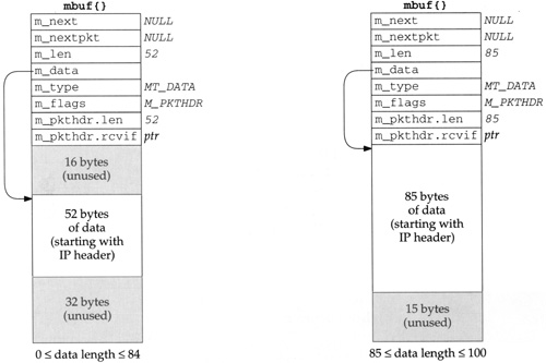
The left mbuf in Figure 2.14 is used when the amount of data is between 0 and 84 bytes. In this figure we assume there are 52 bytes of data: a 20-byte IP header and a 32-byte TCP header (the standard 20-byte TCP header plus 12 bytes of TCP options) but no TCP data. Since the data in the mbuf returned by
m_devgetstarts with the IP header, the realistic minimum value form_lenis 28: 20 bytes for an IP header, 8 bytes for a UDP header, and a 0-length UDP datagram.m_devgetleaves 16 bytes unused at the beginning of the mbuf. Although the 14-byte Ethernet header is not stored here, room is allocated for a 14-byte Ethernet header on output, should the same mbuf be used for output. We’ll encounter two functions that generate a response by using the received mbuf as the outgoing mbuf:icmp_reflectandtcp_respond. In both cases the size of the received datagram is normally less than 84 bytes, so it costs nothing to leave room for 16 bytes at the front, which saves time when building the outgoing datagram. The reason 16 bytes are allocated, and not 14, is to have the IP header longword aligned in the mbuf.If the amount of data is between 85 and 100 bytes, the data still fits in a packet header mbuf, but there is no room for the 16 bytes at the beginning. The data starts at the beginning of the
m_pktdatarray and any unused space is at the end of this array. The mbuf on the right in Figure 2.14 shows this example, assuming 85 bytes of data.Figure 2.15 shows the third type of mbuf created by
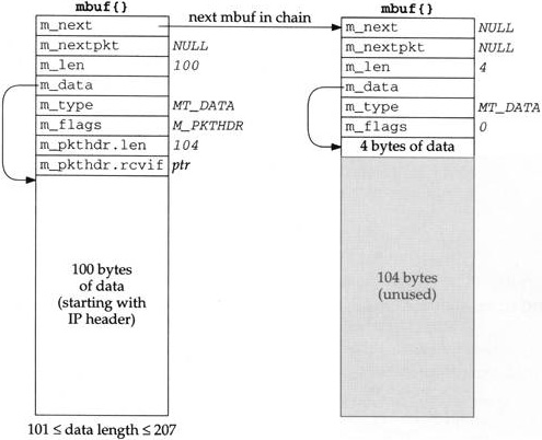
m_devget. Two mbufs are required when the amount of data is between 101 and 207 bytes. The first 100 bytes are stored in the first mbuf (the one with the packet header), and the remainder are stored in the second mbuf. In this example we show a 104-byte datagram. No attempt is made to leave 16 bytes at the beginning of the first mbuf.Figure 2.16 shows the fourth type of mbuf created by
m_devget. If the amount of data is greater than or equal to 208 (MINCLBYTES), one or more clusters are used. The example in the figure assumes a 1500-byte Ethernet frame with 2048-byte clusters. If 1024-byte clusters are in use, this example would require two mbufs, each with theM_EXTflag set, and each pointing to a cluster.

The two macros mtod and dtom are also defined in mbuf.h. They simplify complex mbuf structure expressions.
   #define mtod(m,t)   ((t)((m)->m_data))
   #define dtom(x)     ((struct mbuf *)((int)(x) & ~(MSIZE-1)))
mtod (“mbuf-to-data”) returns a pointer to the data associated with an mbuf, and casts the pointer to a specified type. For example, the code
struct mbuf *m;
struct ip *ip;

ip = mtod(m, struct ip *);
ip->ip_v = IPVERSION;
stores in ip the data pointer of the mbuf (m_data). The type cast is required by the C compiler and the code then references the IP header using the pointer ip. We see this macro used when a C structure (often a protocol header) is stored in an mbuf. This macro works if the data is stored in the mbuf itself (Figures 2.14 and 2.15) or if the data is stored in a cluster (Figure 2.16).
The macro dtom (“data-to-mbuf”) takes a pointer to data anywhere within the data portion of the mbuf and returns a pointer to the mbuf structure itself. For example, if we know that ip points within the data area of an mbuf, the sequence
struct mbuf *m;
struct ip *ip;

m = dtom(ip);
stores the pointer to the beginning of the mbuf in m. By knowing that MSIZE (128) is a power of 2, and that mbufs are always aligned by the kernel’s memory allocator on MSIZE byte blocks of memory, dtom just clears the appropriate low-order bits in its argument pointer to find the beginning of the mbuf.
There is a problem with dtom: it doesn’t work if its argument points to a cluster, or within a cluster, as in Figure 2.16. Since there is no pointer from the cluster back to the mbuf structure, dtom cannot be used. This leads to the next function, m_pullup.
The m_pullup function has two purposes. The first is when one of the protocols (IP, ICMP, IGMP, UDP, or TCP) finds that the amount of data in the first mbuf (m_len) is less than the size of the minimum protocol header (e.g., 20 for IP, 8 for UDP, 20 for TCP). m_pullup is called on the assumption that the remaining part of the header is in the next mbuf on the chain. m_pullup rearranges the mbuf chain so that the first N bytes of data are contiguous in the first mbuf on the chain. N is an argument to the function that must be less than or equal to 100 (MHLEN). If the first N bytes are contiguous in the first mbuf, then both of the macros mtod and dtom will work.
For example, we’ll encounter the following code in the IP input routine:
     if (m->m_len < sizeof(struct ip) &&
         (m = m_pullup(m, sizeof(struct ip))) == 0)  {
             ipstat.ips_toosmall++;
             goto next;
     }
     ip = mtod(m, struct ip *);
If the amount of data in the first mbuf is less than 20 (the size of the standard IP header), m__pullup is called. m_pullup can fail for two reasons: (1) if it needs another mbuf and its call to MGET fails, or (2) if the total amount of data in the mbuf chain is less than the requested number of contiguous bytes (what we called N, which in this case is 20). The second reason is the most common cause of failure. In this example, if m__pullup fails, an IP counter is incremented and the IP datagram is discarded. Notice that this code assumes the reason for failure is that the amount of data in the mbuf chain is less than 20 bytes.
In actuality, m_pullup is rarely called in this scenario (notice that C’s && operator only calls it when the mbuf length is smaller than expected) and when it is called, it normally fails. The reason can be seen by looking at Figure 2.14 through Figure 2.16: there is room in the first mbuf, or in the cluster, for at least 100 contiguous bytes, starting with the IP header. This allows for the maximum IP header of 60 bytes followed by 40 bytes of TCP header. (The other protocols—ICMP, IGMP, and UDP—have headers smaller than 40 bytes.) If the data bytes are available in the mbuf chain (the packet is not smaller than the minimum required by the protocol), then the required number of bytes should always be contiguous in the first mbuf. But if the received packet is too short (m_len is less than the expected minimum), then m_pullup is called and it returns an error, since the required amount of data is not available in the mbuf chain.
Berkeley-derived kernels maintain a variable named
MPFailthat is incremented each timem_pullupfails. On a Net/3 system that had received over 27 million IP datagrams,MPFailwas 9. The counteripstat.ips_toosmallwas also 9 and all the other protocol counters (i.e., ICMP, IGMP, UDP, and TCP) following a failure ofm_pullupwere 0. This confirms our statement that most failures ofm_pullupare because the received IP datagram was too small.
The second use of m_pullup concerns IP reassembly and TCP reassembly. Assume IP receives a packet of length 296, which is a fragment of a larger IP datagram. The mbuf passed from the device driver to IP input looks like the one we showed in Figure 2.16: the 296 bytes of data are stored in a cluster. We show this in Figure 2.17.

The problem is that the IP fragmentation algorithm keeps the individual fragments on a doubly linked list, using the source and destination IP address fields in the IP header to hold the forward and backward list pointers. (These two IP addresses are saved, of course, in the head of the list, since they must be put back into the reassembled datagram. We describe this in Chapter 10.) But if the IP header is in a cluster, as shown in Figure 2.17, these linked list pointers would be in the cluster, and when the list is traversed at some later time, the pointer to the IP header (i.e., the pointer to the beginning of the cluster) could not be converted into the pointer to the mbuf. This is the problem we mentioned earlier in this section: the dtom macro cannot be used if m_data points into a cluster, because there is no back pointer from the cluster to the mbuf. IP fragmentation cannot store the links in the cluster as shown in Figure 2.17.
To solve this problem the IP fragmentation routine always calls m__pullup when a fragment is received, if the fragment is contained in a cluster. This forces the 20-byte IP header into its own mbuf. The code looks like
if (m->m_flags & M_EXT) {
    if ((m = m_pullup (m, sizeof (struct ip))) == 0) {
        ipstat.ips_toosmall++;
        goto next;
    }
    ip = mtod(m, struct ip *);
}
Figure 2.18 shows the resulting mbuf chain, after m__pullup is called. m_pullup allocates a new mbuf, prepends it to the chain, and moves the first 40 bytes of data from the cluster into the new mbuf. The reason it moves 40 bytes, and not just the requested 20, is to try to save an additional call at a later time when IP passes the datagram to a higher-layer protocol (e.g., ICMP, IGMP, UDP, or TCP). The magic number 40 (max_protohdr in Figure 7.17) is because the largest protocol header normally encountered is the combination of a 20-byte IP header and a 20-byte TCP header. (This assumes that other protocol suites, such as the OSI protocols, are not compiled into the kernel.)

In Figure 2.18 the IP fragmentation algorithm can save a pointer to the IP header contained in the mbuf on the left, and this pointer can be converted into a pointer to the mbuf itself using dtom at a later time.
The reassembly of TCP segments uses a different technique to avoid calling m_pullup. This is because m_pullup is expensive: memory is allocated and data is copied from a cluster to an mbuf.TCP tries to avoid data copying whenever possible.
Chapter 19 of Volume 1 mentions that about one-half of TCP data is bulk data (often 512 or more bytes of data per segment) and the other half is interactive data (of which about 90% of the segments contain less than 10 bytes of data). Hence, when TCP receives segments from IP they are usually in the format shown on the left of Figure 2.14 (a small amount of interactive data, stored in the mbuf itself) or in the format shown in Figure 2.16 (bulk data, stored in a cluster). When TCP segments arrive out of order, they are stored on a doubly linked list by TCP. As with IP fragmentation, fields in the IP header are used to hold the list pointers, which is OK since these fields are no longer needed once the IP datagram is accepted by TCP. But the same problem arises with the conversion of a list pointer into the corresponding mbuf pointer, when the IP header is stored in a cluster (Figure 2.17).
To solve the problem, we’ll see in Section 27.9 that TCP stores the mbuf pointer in some unused fields in the TCP header, providing a back pointer of its own from the cluster to the mbuf, just to avoid calling m_pullup for every out-of-order segment. If the IP header is contained in the data portion of the mbuf (Figure 2.18), then this back pointer is superfluous, since the dtom macro would work on the list pointer. But if the IP header is contained in a cluster, this back pointer is required. We’ll examine the source code that implements this technique when we describe tcp_reass in Section 27.9.
We’ve described three main points about m_pullup.
Most device drivers do not split the first portion of an IP datagram between mbufs. Therefore the possible calls to
m_pullupthat we’ll encounter in every protocol (IP, ICMP, IGMP, UDP, and TCP), just to assure that the protocol header is stored contiguously, rarely take place. When these calls tom_pullupdo occur, it is normally because the IP datagram is too small, in which casem_pullupreturns an error, the datagram is discarded, and an error counter is incremented.m_pullupis called for every received IP fragment, when the IP fragment is stored in a cluster. This means thatm_pullupis called for almost every received fragment, since the length of most fragments is greater than 208 bytes.As long as TCP segments are not fragmented by IP, the receipt of a TCP segment, whether it be in order or out of order, should not invoke
m_pullup. This is one reason to avoid IP fragmentation with TCP.
Figure 2.19 lists the macros and Figure 2.20 lists the functions that we’ll encounter in the code that operates on mbufs. The macros in Figure 2.19 are shown as function prototypes, not as #define statements, to show the data types of the arguments. We will not go through the source code implementation of these routines since they are concerned primarily with manipulating the mbuf data structures and involve no networking issues. Also, there are additional mbuf macros and functions used elsewhere in the Net/3 sources that we don’t show in these two figures since we won’t encounter them in the text.
Table 2.19. Mbuf macros that we’ll encounter in the text.
Macro | Description |
|---|---|
MCLGET | Get a cluster (an external buffer) and set the data pointer ( void MCLGET(struct mbuf *m, int nowait; |
MFREE | Free the single mbuf pointed to by m. If m points to a cluster ( void MFREE(struct mbuf *m, struct mbuf *n; |
MGETHDR | Allocate an mbuf and initialize it as a packet header. This macro is similar to void MGETHDR(struct mbuf *m, int nowait, int type); |
MH_ALIGN | Set the void MH_ALIGN(struct mbuf *m, int len); |
M_PREPEND | Prepend len bytes of data in front of the data in the mbuf pointed to by m. If room exists in the mbuf, just decrement the pointer void M_PREPEND(struct mbuf *m, int len, int nowait); |
dtom | Convert the pointer x, which must point somewhere within the data area of an mbuf, into a pointer to the beginning of the mbuf. struct mbuf *dtom(void *x); |
mtod | Type cast the pointer to the data area of the mbuf pointed to by m to type. type mtod(struct mbuf *m, type); |
Table 2.20. Mbuf functions that we’ll encounter in the text.
Function | Description |
|---|---|
m_adj | Remove len bytes of data from the mbuf pointed to by m. If len is positive, that number of bytes is trimmed from the start of the data in the mbuf chain, otherwise the absolute value of len bytes is trimmed from the end of the data in the mbuf chain. void m_adj(struct mbuf *m, int len); |
m_cat | Concatenate the mbuf chain pointed to by n to the end of the mbuf chain pointed to by m. We encounter this function when we describe IP reassembly (Chapter 10). void m_cat(struct mbuf *m, struct mbuf *n); |
m_copy | A three-argument version of struct mbuf *m_copy(struct mbuf *m, int Ioffset, int len); |
m_copydata | Copy len bytes of data from the mbuf chain pointed to by m into the buffer pointed to by cp. The copying starts from the specified byte offset from the beginning of the data in the mbuf chain. void m_copydata(struct mbuf *m, int offset, int len, caddr_t cp); |
m_copyback | Copy len bytes of data from the buffer pointed to by cp into the mbuf chain pointed to by m. The data is stored starting at the specified byte offset in the mbuf chain. The mbuf chain is extended with additional mbufs if necessary. void m_copyback(struct mbuf *m, int offset, int len, caddr_t cp); |
m_copym | Create a new mbuf chain and copy len bytes of data starting at offset from the mbuf chain pointed to by m. A pointer to the new mbuf chain is returned as the value of the function. If len equals the constant struct mbuf *m_copym(struct mbuf *m, int offset, int len, int nowait); |
m_devget | Create a new mbuf chain with a packet header and return the pointer to the chain. The struct mbuf *m_devget(char *buf, int len, int off, struct ifnet *ifp, void (*copy)(const void *, void *, u_int)); |
m_free | A function version of the macro struct mbuf *m_free(struct mbuf *m); |
m_freem | Free all the mbufs in the chain pointed to by m. void m_freem(struct mbuf *m); |
m_get | A function version of the struct mbuf *m_get(int nowait, int type; |
m_getclr | This function calls the struct mbuf *m_getclr(int nowait, int type); |
| A function version of the struct mbuf *m_gethdr(int nowait, int type); |
m_pullup | Rearrange the existing data in the mbuf chain pointed to by m so that the first len bytes of data are stored contiguously in the first mbuf in the chain. If this function succeeds, then the struct mbuf *m_pullup(struct mbuf *m, int len); |
In all the prototypes the argument nowait is either M_WAIT or M_DONTWAIT, and the argument type is one of the MT_xxx constants shown in Figure 2.10.
As an example of M_PREPEND, this macro was called when the IP and UDP headers were prepended to the user’s data in the transition from Figure 1.7 to Figure 1.8, causing another mbuf to be allocated. But when this macro was called again (in the transition from Figure 1.8 to Figure 2.2) to prepend the Ethernet header, room already existed in the mbuf for the headers.
The data type of the last argument for
m_copydataiscaddr_t, which stands for “core address.” This data type is normally defined in<sys/types.h>to be achar *. It was originally used internally by the kernel, but got externalized when used by certain system calls. For example, themmapsystem call, in both 4.4BSD and SVR4, usescaddr_tas the type of the first argument and as the return value type.
This section summarizes the types of data structures we’ll encounter in the Net/3 networking code. Other data structures are used in the Net/3 kernel (interested readers should examine the <sys/queue.h> header), but the following are the ones we’ll encounter in this text.
An mbuf chain: a list of mbufs, linked through the
m_nextpointer. We’ve seen numerous examples of these already.A linked list of mbuf chains with a head pointer only. The mbuf chains are linked using the
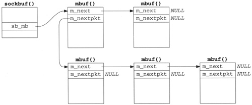
m_nextpktpointer in the first mbuf of each chain.Figure 2.21 shows this type of list. Examples of this data structure are a socket’s send buffer and receive buffer.
The top two mbufs form the first record on the queue, and the three mbufs on the bottom form the second record on the queue. For a record-based protocol, such as UDP, we can encounter multiple records per queue, but for a protocol such as TCP that has no record boundaries, we’ll find only a single record (one mbuf chain possibly consisting of multiple mbufs) per queue.
To append an mbuf to the first record on the queue requires going through all the mbufs comprising the first record, until the one with a null
m_nextpointer is encountered. To append an mbuf chain comprising a new record to the queue requires going through all the records until the one with a nullm_nextpktpointer is encountered.A linked list of mbuf chains with head and tail pointers.
Figure 2.22 shows this type of list. We encounter this with the interface queues (Figure 3.13), and showed an earlier example in Figure 2.2.
The only change in this figure from Figure 2.21 is the addition of a tail pointer, to simplify the addition of new records.
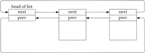
A doubly linked, circular list.
Figure 2.23 shows this type of list, which we encounter with IP fragmentation and reassembly (Chapter 10), protocol control blocks (Chapter 22), and TCP’s out-of-order segment queue (Section 27.9).
The elements in the list are not mbufs—they are structures of some type that are defined with two consecutive pointers: a next pointer followed by a previous pointer. Both pointers must appear at the beginning of the structure. If the list is empty, both the next and previous pointers of the head entry point to the head entry.
For simplicity in the figure we show the back pointers pointing at another back pointer. Obviously all the pointers contain the address of the structure pointed to, that is the address of a forward pointer (since the forward and backward pointer are always at the beginning of the structure).
This type of data structure allows easy traversal either forward or backward, and allows easy insertion or deletion at any point in the list.
The functions
insqueandremque(Figure 10.20) are called to insert and delete elements in the list.

One obvious advantage with clusters is being able to reduce the number of mbufs required to contain large amounts of data. For example, if clusters were not used, it would require 10 mbufs to contain 1024 bytes of data: the first one with 100 bytes of data, the next eight with 108 bytes of data each, and the final one with 60 bytes of data. There is more overhead involved in allocating and linking 10 mbufs, than there is in allocating a single mbuf containing the 1024 bytes in a cluster. A disadvantage with clusters is the potential for wasted space. In our example it takes 2176 bytes using a cluster (2048+128), versus 1280 bytes without a cluster (10 x 128).
An additional advantage with clusters is being able to share a cluster between multiple mbufs. We encounter this with TCP output and the m_copy function, but describe it in more detail now.
As an example, assume the application performs a write of 4096 bytes to a TCP socket. Assuming the socket’s send buffer was previously empty, and that the receiver’s window is at least 4096, the following operations take place. One cluster is filled with the first 2048 bytes by the socket layer and the protocol’s send routine is called. The TCP send routine appends the mbuf to its send buffer, as shown in Figure 2.24, and calls tcp_output.

The socket structure contains the sockbuf structure, which holds the head of the list of mbufs on the send buffer: so_snd.sb_mb.
Assuming a TCP maximum segment size (MSS) of 1460 for this connection (typical for an Ethernet), tcp_output builds a segment to send containing the first 1460 bytes of data. It also builds an mbuf containing the IP and TCP headers, leaves room for a link-layer header (16 bytes), and passes this mbuf chain to IP output. The mbuf chain ends up on the interface’s output queue, which we show in Figure 2.25.
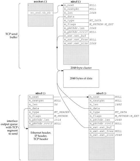
In our UDP example in Section 1.9, UDP took the mbuf chain containing the datagram, prepended an mbuf for the protocol headers, and passed the chain to IP output. UDP did not keep the mbuf in its send buffer. TCP cannot do this since TCP is a reliable protocol and it must maintain a copy of the data that it sends, until the data is acknowledged by the other end.
In this example tcp_output calls the function m_copy, requesting a copy be made of 1460 bytes, starting at offset 0 from the start of its send buffer. But since the data is in a cluster, m_copy creates an mbuf (the one on the lower right of Figure 2.25) and initializes it to point to the correct place in the existing cluster (the beginning of the cluster in this example). The length of this mbuf is 1460, even though an additional 588 bytes of data are in the cluster. We show the length of the mbuf chain as 1514, accounting for the Ethernet, IP, and TCP headers.
We also show this mbuf on the lower right of Figure 2.25 containing a packet header, yet this isn’t the first mbuf in the chain. When
m_copymakes a copy of an mbuf that contains a packet header and the copy starts from offset 0 in the original mbuf, the packet header is also copied verbatim. Since this mbuf is not the first mbuf in the chain, this extraneous packet header is just ignored. Them_pkthdr.lenvalue of 2048 in this extraneous packet header is also ignored.
This sharing of clusters prevents the kernel from copying the data from one mbuf into another—a big savings. It is implemented by providing a reference count for each cluster that is incremented each time another mbuf points to the cluster, and decremented each time a cluster is released. Only when the reference count reaches 0 is the memory used by the cluster available for some other use. (See Exercise 2.4.)
For example, when the bottom mbuf chain in Figure 2.25 reaches the Ethernet device driver and its contents have been copied to the device, the driver calls m_freem. This function releases the first mbuf with the protocol headers and then notices that the second mbuf in the chain points to a cluster. The cluster reference count is decremented, but since its value becomes 1, it is left alone. It cannot be released since it is still in the TCP send buffer.
Continuing our example, tcp_output returns after passing the 1460-byte segment to IP, since the remaining 588 bytes in the send buffer don’t comprise a full-sized segment. (In Chapter 26 we describe in detail the conditions under which tcp_output sends data.) The socket layer continues processing the data from the application: the remaining 2048 bytes are placed into an mbuf with a cluster, TCP’s send routine is called again, and this new mbuf is appended to the socket’s send buffer. Since a full-sized segment can be sent, tcp_output builds another mbuf chain with the protocol headers and the next 1460 bytes of data. The arguments to m_copy specify a starting offset of 1460 bytes from the start of the send buffer and a length of 1460 bytes. This is shown in Figure 2.26, assuming the mbuf chain is again on the interface output queue (so the length of the first mbuf in the chain reflects the Ethernet, IP, and TCP headers).
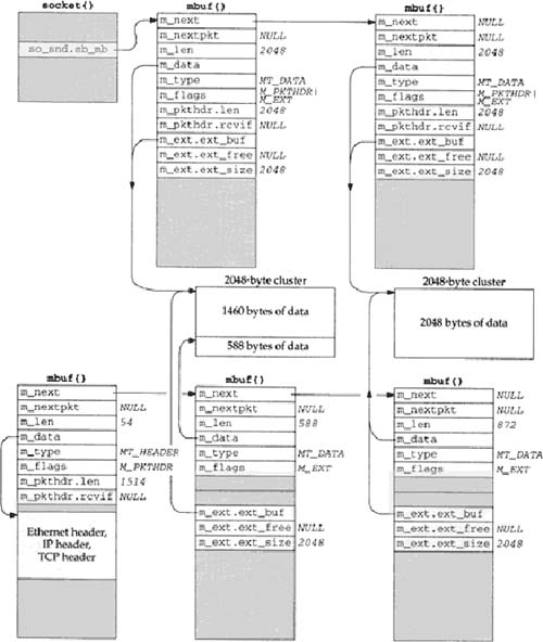
This time the 1460 bytes of data come from two clusters: the first 588 bytes are from the first cluster in the send buffer and the next 872 bytes are from the second cluster in the send buffer. It takes two mbufs to describe these 1460 bytes, but again m_copy does not copy the 1460 bytes of data—it references the existing clusters.
This time we do not show a packet header with either of the mbufs on the bottom right of Figure 2.26. The reason is that the starting offset in the call to
m_copyis nonzero. Also, we show the second mbuf in the socket send buffer containing a packet header, even though it is not the first mbuf in the chain. This is a property of thesosendfunction, and this extraneous packet header is just ignored.
We encounter the m_copy function about a dozen times throughout the text. Although the name implies that a physical copy is made of the data, if the data is contained in a cluster, an additional reference is made to the cluster instead.
Mbufs are far from perfect and they are berated regularly. Nevertheless, they form the basis for all the Berkeley-derived networking code in use today.
A research implementation of the Internet protocols by Van Jacobson [Partridge 1993] has done away with the complex mbuf data structures in favor of large contiguous buffers. [Jacobson 1993] claims a speed improvement of one to two orders of magnitude, although many other changes were made besides getting rid of mbufs.
The complexity of mbufs is a tradeoff that avoids allocating large fixed buffers that are rarely filled to capacity. At the time mbufs were being designed, a VAX-11/780 with 4 megabytes of memory was a big system, and memory was an expensive resource that needed to be carefully allocated. Today memory is inexpensive, and the focus has shifted toward higher performance and simplicity of code.
The performance of mbufs is also dependent on the amount of data stored in the mbuf. [Hutchinson and Peterson 1991] show that the amount of time required for mbuf processing is nonlinear with respect to the amount of data.
We’ll encounter mbufs in almost every function in the text. Their main purpose is to hold the user data that travels from the process to the network interface, and vice versa, but mbufs are also used to contain a variety of other miscellaneous data: source and destination addresses, socket options, and so on.
There are four types of mbufs, depending whether the M_PKTHDR and M_EXT flags are on or off:
no packet header, with 0 to 108 bytes of data in mbuf itself,
packet header, with 0 to 100 bytes of data in mbuf itself,
no packet header, with data in cluster (external buffer), and
packet header, with data in cluster (external buffer).
We looked at the source code for a few of the mbuf macros and functions, but did not present the source code for all the mbuf routines. Figures 2.19 and 2.20 provide the function prototypes and descriptions of all the mbuf routines that we encounter in the text.
We looked at the operation of two functions that we’ll encounter: m_devget, which is called by many network device drivers to store a received frame; and m_pullup, which is called by all the input routines to place the required protocol headers into contiguous storage in an mbuf.
The clusters (external buffers) pointed to by an mbuf can be shared by m_copy. This is used, for example, by TCP output, because a copy of the data being transmitted must be maintained by the sender until that data is acknowledged by the other end. Sharing clusters through reference counts is a performance improvement over making a physical copy of the data.
2.1 | In Figure 2.9 the |
2.1 | The |
2.2 | In Section 2.6 we listed two reasons that |
2.2 | The caller asks for more than 100 ( |
2.3 | To avoid the problems we described in Section 2.6 with the |
2.3 | This is infeasible since clusters can be pointed to by multiple mbufs (Section 2.9). Also, there is no room in a cluster for a back pointer (Exercise 2.4). |
2.4 | Since the size of an mbuf cluster is a power of 2 (typically 1024 or 2048), space cannot be taken within the cluster for the reference count. Obtain the Net/3 sources (Appendix B) and determine where these reference counts are stored. |
2.4 | In the macros |
2.5 | In Figure 2.5 we noted that the two counters |