
Chapter 8. I/O Device Hacks
Introduction: Hacks #75-84
As you travel through a PC system from the inside to the outside, you end up at the I/O, or Input and Output systems: serial, parallel, game, USB, and IEEE-1394 ports. There isn’t a great deal here—just a couple of ports that slog along at what seems like a snail’s pace compared to blazing CPU speeds and outrageous disk drive transfer rates—but what you do have can use some understanding and hacking to get them shipshape. By shipshape I mean working at the speeds they are supposed to, not conflicting with other devices or themselves, and operating in the correct mode for the peripherals connected to them.
While you shouldn’t look for any spectacular performance boost in your I/O ports, they can be one of the most frustrating parts of a PC to deal with if things do not work right.
While the hacks in this chapter might not apply to your shiny new legacy-free laptop, they will help you out if you’re working with an older PC used by a friend, school, or church, or trying to recycle an old system as a server or Linux system.
If you don’t have enough ports, there are ways to add more—from bending the COM port configuration rules for connecting conventional I/O devices to expanding port availability with USB devices.
Tip
Rules? Do you mean to imply that there are actually rules you should abide by when configuring PC I/O devices? Of course—no computer system would work consistently if there were not a few rules lying around and being enforced. Indeed, computing is based on rules from the lowest level machine code that starts things up, to, um, the lowest level machine code that actually runs in the CPU.
Face it, the PC didn’t just pop out of some guy’s garage ready to run DOS, Windows, Linux, Solaris x86, BeOS, or whatever you can get to run on your system and drive’s thousands of possible combinations of modems, video cards, network cards, sound cards, keyboards, mice, and disk drives. Somewhere, sometime, you will run into a device or port that needs a specific configuration when the PC stops cooperating. Knowing a few simple configuration rules and how to work around them may not make your PC run faster, but the right configuration can make a PC run properly if not better.
Basic PC Configuration Rules
The details of how the PC turned from a renegade project at IBM to a mega-industry go a long way toward explaining the limitations of the systems we have today. The basic PC configuration rules explain why even some new components consume both old and new resources.
The original IBM PC provided a meager hardware addressing range 400 bytes wide into which all the possible hardware (at the time) would exchange commands and data. In addition, eight interrupt request lines (IRQs) were available for hardware to signal the CPU and operating system that attention was needed. Further, it was anticipated that some devices would benefit from direct memory access (DMA) capabilities, and six channels were provided for that.
Within the PC, there are a few prescribed devices and functions that are absolutes no matter the generation, architecture, manufacturer, CPU, chipset, or peripherals involved. The system is destined to have timers, clocks, and a keyboard but no reservation for a display or I/O devices, which are optional.
The Bad Old Days
Shortly into the life of the PC, IBM and other vendors began to incorporate some new devices that led to the explosion of the PC into the consumer and business market. For the first three to four years of the PC’s existence, the resources available for expansion and functionality were adequate, but in the years after that, they proved quite limiting. The resources, devices, and obvious limitations for expansion are listed in Table 8-1. This table represents the basic PC/AT (286 and higher) configuration, including many add-on components that were developed along the way, before PCI and Plug and Play began to change the PC platform. Note that several devices/functions, marked with an asterisk (*) in the “System device” column, are dedicated system devices—these represent resources and functions that cannot be altered.
Device/function | Address | IRQ | DMA | System device |
RAM refresh | 0 | * | ||
System timer | 40h | 0 | * | |
Keyboard | 60h | 1 | * | |
Cascade (see note) for IRQ 8-15 | 2 | * | ||
COM2 | 2F8h | 3 | ||
COM4 | 2E8h | 3 | ||
COM1 | 3F8h | 4 | ||
COM3 | 2F8h | |||
LPT2 | 278h | 5 | ||
Sound card | 220h | 1, 3, or 5 | ||
Diskette adapter | 3F0h | 6 | 2 | * |
LPT1 | 3BCh or 378h | 7 | ||
Real-time clock | 70h | 8 | * | |
Reserved for 16-bit ISA | 9 | |||
ISA-bus network card | 280h | 10 | ||
SCSI adapter | 330h | 11 | 3 or 5 | |
PS/2 mouse port | 64h | 12 | * | |
Numeric coprocessor | F0h | 13 | * | |
Hard disk interface | 1F0h | 14 | ||
Second hard disk interface | 170h | 15 | ||
VGA card | 3B0 or 3C0 |
Tip
The “cascade” designation for IRQ 2 means that the second interrupt chip for IRQs 8-15 feeds or triggers the IRQ 2 signal in the first chip. The IRQ 2 signal line is not available for use by plug-in devices or other system board devices.
Most of the devices in early PCs, from essential system resources through hard drive interfaces and video cards, provided little or no hardware configuration options: they use fixed I/O addresses and IRQs, and anything you added to the system had to work around what was left. Even in a PC-AT system, you have only 16 total IRQs and 6 total DMA channels to choose from, with seven of the IRQs (0, 1, 2, 6, 8, 9, 13) taken by the system and another three taken by normal devices (hard drive using 14 and 15, and mouse port using 12). This leaves only six IRQ (3, 4, 5, 7, 10, and 11) lines to work with. With COM ports 1 and 2 present, even if those ports are not in use, IRQ 3 and 4 are spoken for, leaving four lines for expansion.
The PC-AT architecture ties up two IRQ lines, 2 and 9, to accommodate devices on the 16-bit ISA bus. IRQ2 has typically never been accessible on either 8- or 16-bit ISA I/O slots because it is the IRQ line used by the second IRQ chip that provides IRQs 8-15 to the 16-bit bus. Whether or not you can use IRQ9 for an add-in device has been an ongoing question for years because it was thought that the IRQ-handling code in BIOS and operating systems confused it with IRQ2. This seems not to be the case, and since the IRQ9 signal does appear on the 16-bit ISA bus connector, it seems that we can use it. Many have done so successfully and without problems. This increases the available IRQ count to five, but those five lines get used up quickly.
In the PC-AT architecture, a sound card and network adapter will use up another two IRQ lines (typically IRQs 5 and 10), leaving only three lines (IRQs 7, 9, and 11) for future expansion. If you want to get a total of four serial/COM ports working simultaneously [Hack #77] , you need to figure out a way to use two of these IRQ lines, leaving only one available IRQ for expansion. If you add a SCSI host adapter, IRQ 11 gets used and you’re out of expansion capabilities.
Toward a Modern Bus: VESA, PCI, AGP, and Beyond
It’s easy to see under the older architecture that if you want to add a web camera, a connection to your PDA or cell phone, an external disk drive, or any other sophisticated device, you could run out of IRQ lines and be stuck. It was obvious to Intel and Microsoft that something had to be done to provide additional expansion capabilities. This revelation was coincident with the need for higher-speed peripheral connectivity; the old 16 MHz 16-bit ISA bus was not going to deliver adequate graphics or connectivity performance for the future.
The PC industry, including IBM, and later the Video Electronics Standard Association (VESA), saw the need for better performance, more configuration options, and easier configuration of the PC. Before the PC got the PCI bus (Peripheral Component Interconnect), it struggled through IBM’s MicroChannel Architecture, EISA (Enhanced Industry Standard Architecture), and VESA’s VLB (VESA Local Bus) enhancements on various PC models—mostly through the i80386 and i80486 generations of PCs. Intel, Microsoft, and others finally were able to create and drive to market the current PCI bus standard as well as support Plug and Play routines in the system BIOS and hardware devices.
The PCI bus provides a totally separate set of electronic circuits, addressing and data lines, and configuration capabilities to the PC. PCI removes issues of exclusive IRQ assignments, expands the hardware I/O addressing range, speeds up I/O data transfer rates, and provides for automatic, or at least more intelligent, hardware device configuration. In fact, it is virtually impossible to manually configure a PCI device because there are no jumpers or switches and very few devices support setting the configuration through software; configuration is done entirely through Plug and Play processes.
PCI is exactly what the PC needed to expand beyond the limitations of fixed hardware addressing and limited IRQ and DMA resources. While the premise behind PCI for reducing resource constraints still has advantages, PCI is limited in data throughput speed as a 33-MHz bus. This bus speed is not nearly fast enough for the demands of multimedia applications like games and full-motion video. The PCI bus is overdue for a speed enhancement. Just as ISA, MicroChannel, and EISA were not fulfilling the need for speed, the original PCI bus has all but outlived its ability to deliver data fast enough, leading to the evolution of PCI-X with 266 MHz and 533 MHz speeds provided in some systems.
From PCI evolved the Universal Serial Bus (USB) and Texas Instruments’s IEEE-1394 (also known by Apple’s brand name of FireWire and Sony’s brand name of i.Link), high-speed interfaces for supporting additional new devices in PCs and Apple Macintosh systems.
USB removed any foreseeable restrictions on the number and type of peripheral device imaginable to date. Essentially consuming one PCI port but with a more direct interface to the CPU than the bus itself, USB 1.1 and 2.0 can accommodate up to 256 devices through a single I/O port, and USB 2.0 has achieved data transfer rates up to 57 megabytes per second (MBps), superceding the original IEEE-1394.
IEEE-1394 ports have been perceived as competition to USB 1.1, but it turns out they found a niche in high-end video and data storage uses, with speeds up to 50 MBps. Adoption and use of IEEE-1394 has been slow due to technology licensing fees that increase per-system costs that can only be justified in higher-priced, higher-performance devices.
While external I/O gained from USB and IEEE-1394, the inside of the PC didn’t get a performance boost until the Advanced Graphics Port (AGP) was implemented, providing a dedicated path from the CPU to the video adapter. The AGP has experienced performance enhancements that take its data throughput to well above 800 MBps. Although AGP is fast, it’s limited to being a single-purpose I/O path (graphics), so PCI-X is the contender for speeding up internal I/O expansion to multiple devices.
PCI, USB, IEEE-1394, and AGP provide the PC with higher performance capabilities but also free up critical resources that can be used for legacy/ISA devices if you can find a system board that still has an ISA bus slot or two.
I/O Speed
To give you an idea of the data throughput rates for various I/O technologies, I’ve provided a listing of I/O technologies and their data rates in Table 8-2. With the exception of devices connected through the PCI, USB, or IEEE-1394 interfaces, every I/O technology, including most IDE disk drive interfaces, requires legacy/ISA IRQ and possibly DMA configuration resources.
Port | Maximum data transfer rate |
Serial/COM port—8250 | 9.6 kilobits/s |
Serial/COM port—16550A | 115 kilobits/s |
Standard Parallel/LPT port | 115 kilobytes/s (10x faster than serial/COM) |
10 Base/T Ethernet | 10 megabits/s |
USB 1.1 | 12 megabits/s |
ECP/EPP parallel port | 3 megabytes/s |
8-bit ISA bus | 8 megabytes/s |
16-bit ISA bus | 16 megabytes/s |
IDE | 3.3-16.7 megabytes/s |
SCSI-1 | 5 megabytes/s |
SCSI-2 (Fast SCSI, Fast Narrow SCSI) | 10 megabytes/s |
100BaseT Ethernet | 100 megabits/s |
Fast Wide SCSI (Wide SCSI) | 20 megabytes/s |
Ultra SCSI (SCSI-3, Fast-20, Ultra Narrow) | 20 megabytes/s |
UltraIDE | 33 megabytes/s |
PCI bus | 33 megabytes/s |
Wide Ultra SCSI (Fast Wide 20) | 40 megabytes/s |
Ultra2 SCSI | 40 megabytes/s |
Ultra ATA (IDE) | 66-133 megabytes/s |
IEEE-1394 | 100-400 megabits/s |
USB 2.0 | 480 megabits/s |
Wide Ultra2 SCSI | 80 megabytes/s |
Ultra3 SCSI | 80 megabytes/s |
1000BaseT Ethernet | 1,000 megabits/s |
Wide Ultra3 SCSI | 160 megabytes/s |
FC-AL Fiber Channel | 100-400 megabytes/s |
AGP video bus | 2.1 gigabytes/s (AGP 8x) |
Tip
The speeds listed in Table 8-2 are from their respective maximum throughput specifications. Operating system, device driver, application, system hardware, cabling, and device overhead will impact the actual transfer speeds you obtain.
If you are feeling a bit of I/O-performance envy over the tremendous throughput of the AGP bus, you are not alone. Disk drive performance, perhaps the most significant PC performance bottleneck, could benefit significantly from higher bus and throughput speeds, but the industry is still waiting for economical disk drive technology that can accommodate higher data transfer rates.
Let Windows Tell You About I/O Card Conflicts
Early SCSI adapters and sound cards arrived in the PC market at about the same time. With only the known IBM PC design reference to go by, and no industry-standards group to keep track of who was developing what devices, none of the designers of various devices knew what the others were doing. In the face of limited available resources, everyone scrambled to establish a foothold and hoped they didn’t get trampled.
It was not uncommon to encounter a SCSI host adapter and a sound card that both used the same address (often 220h or 330h). Obviously if both adapters used the same address this combination would not work. If software addressed the sound card, it would wrongly get the attention of the SCSI host adapter; if software addressed the SCSI host adapter, it would wrongly get the attention of the sound card.
In such battles, the device with more clout wins, and such was the case with the sound card. Many more people were buying sound cards than were investing in expensive SCSI devices, so makers of the SCSI adapters moved off to address 330h and the sound card manufacturers held the ground at 220h.
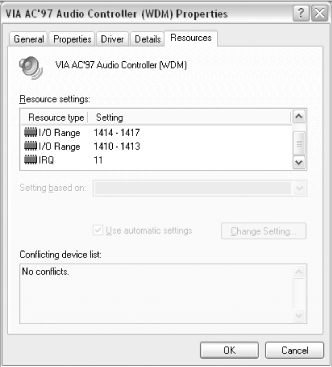
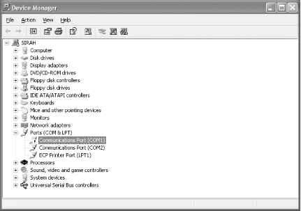
You need to know which devices use which addresses and configure them so there is no direct conflict. To find out if you have any device conflicts and drill down to what they are, open Windows Device Manager. If you see a yellow dot with an exclamation point in it, you have a conflict. If you see a red x, the device is disabled. Figure 8-1 shows a device in Device Manager with no conflicts; this is the picture you want to see. If you see a yellow dot, double-click it to open the Properties dialog for the device and then select the Resources tab. Any conflicts will be shown in the lower text box, identifying the conflicting device. To resolve the conflict, you must change the configuration of one of the devices.
Sometimes resolving conflicts this way will not solve problems. In addition to making sure things don’t collide, be sure to look out for 300h, the problem I/O address, and also make sure you’re leaving enough room between addresses.
Avoid I/O Address 300h
Of the known IBM I/O devices, one significant but very rare device is often overlooked: the Prototype Card. IBM created and sold this special I/O card for hardware developers to use to hack together new I/O devices. An open PC design and architecture has obviously been good for the existence of the PC business, but a few designers neglected to fully understand the PC design when they created new devices. IBM assigned or reserved I/O address 300h to the Prototype Card and accommodated recognition of the Prototype Card’s presence in the BIOS, as did some DOS and Windows software. Engineers that ignored these facts caused no end of trouble for PC installers and users.
This bit of trivia usually isn’t significant until you try to add an ISA device that uses address 300h, as many early network interface cards do. IBM had not accounted for network cards except their own for connection to Token Ring LANs and mainframes, and those devices did not use address 300h, because IBM knew that address was reserved for the Prototype Card.
This problem first came to light in the mid-90s with early Ethernet cards. A technician would install a new network card, unaware of the potential problem between the Prototype Card and the default configuration some of these cards used: address 300. The rest of the network card installation (drivers and related connectivity software) would seem to go well, connectivity with a server and other workstations could be established, and things seemed just fine—for a while. After “a while,” some applications or network functions would cease to work and the trouble began; the network that worked once now worked intermittently. Finding the cause of the problem escaped technicians until some other network card, probably using a different default address, was installed. The card that was removed could appear to be OK in another system but ultimately would never work right until its address was changed to something other than 300h.
Be wary of and avoid using hardware addresses that are reserved for other devices, follow the configuration rules, and use the de facto standard addresses for your new devices.
Use an I/O Address with Enough Room
Most 8- and 16-bit ISA network adapters allow you to set the base I/O address to 340h. Since most adapters require an address range of only a few bytes beyond the base address, using address 340h is typically not a problem. If your network or other I/O adapter requires more address space, it may overlap onto another card’s base address, specifically the LPT1/parallel port at address 378h [Hack #76] , which will cause one or both of the adapters to stop working correctly.
In the case of most network adapters, you can reconfigure the card to use another base address (but not 300h!) to avoid colliding with another device. 280h is a typical alternative to try.
Be sure to research the complete addressing requirements of all your adapter cards and configure them so they do not overlap the address space of other adapters.
Break the Rules with LPT Ports
Get back the use of IRQ lines by changing your LPT port settings.
Even though none of the early standard LPT port implementations ever used an IRQ line, Windows still insists that IRQ 7 or 5 is assigned to an LPT port (Windows performs no actual test for this—it’s a programmed assumption), so any other use of these IRQ lines causes Windows to erroneously flag such use as a conflict. Some of us are finicky about conflicts, and some programs may not accept port connections if a conflict exists.
Trying to use the same IRQ as the parallel port is a potential conflict only if both of these are true:
If the parallel port is used as a standard or even bidirectional port for simply dumping text to a printer, you can ignore this conflict because the chipset and simpler printing devices that may be attached to it have no need to use the IRQ line. Thus, you gain a free IRQ line to use for other devices despite the apparent conflict.
If your printer attaches to your PC through a USB port, or is connected as a network device or shared on another computer, you do not need the LPT port at all. In this case, you can disable the LPT port to ensure that the IRQ is never used by the LPT port, and is available for other uses in the BIOS [Hack#14] and in Windows through Device Manager with these steps:
Right-click My Computer and select Properties.
Select the Hardware tab and then click the Device Manager button.
In Device Manager click on the plus (+) sign to the left of Ports (COM & LPT).
Right-click the Printer port entry and then select Disable.
Close Device Manager.
Shut down or restart the system and configure your other device to use the IRQ (typically IRQ 7) formerly used by the LPT port.
Break the Rules with COM Ports
Allow more than two COM ports to work simultaneously without conflicts.
We don’t seem to use COM ports very much these days, but even new USB-connected devices emulate the tried-and-true methods of serial communications in today’s technology. The plain old serial port is still imperative for communicating with most of the devices that make the Internet possible: modems, routers, switches, and headless servers.
In the design of the original PC, IBM created a deliberate conflict between COM ports that has never been resolved through any change of standards or design. The conflict is the IRQ assignments for COM1 and COM3, which both use IRQ4, and COM2 and COM4, which both use COM3. Apparently IBM never thought anyone would want to use more than two COM ports at the same time: you cannot use COM1 and COM3 at the same time, nor COM2 and COM4 at the same time.
This conflict came to light as early online pioneers started running bulletin board systems with multiple modems to allow multiple users access at the same time. Early communications software relied on the system BIOS for many hardware I/O functions, and serial communications was one of them. The BIOS, of course, was hard-coded to adhere to strict rules, and COM port configuration and IRQs were encompassed by them.
As time passed, developers determined the BIOS functions were not the only or best way to get the hardware to do what they wanted. Flexibility in software and hardware configurations came about to the advantage of users. They could work around the limitations of the BIOS by addressing system hardware directly, which worked well if it was certain that other hardware and software were not going to get in the way.
The first thing that got in the way of expanding the communications capabilities of the PC was the COM-port IRQ conflict. The conflict could only be resolved through some clever hacking of software and hardware to make things work. Software programmers had to know and provide for the many different addresses and IRQs that were likely to be available in the PC, and hardware makers or technically inclined users had to know how to get the hardware configured to their advantage.
Since the source of conflict with using multiple COM ports at the same time is the lack of a unique IRQ for each port, you need to scrounge for two more IRQ lines to give the COM3 and COM4 ports their own IRQs.
Tip
Even if you are not going to physically plug in additional COM ports, you may have to reconfigure the virtual COM ports created by USB-to-serial adapters and ensure that each has a nonconflicting setting to work with. See the steps at the end of this hack to make COM port settings changes.
Recovering an unused IRQ or two from one or more LPT ports [Hack #76] can be a rather fortunate coincidence. You can usually repurpose IRQ7 for one of the four COM ports. You may be able to repurpose IRQ5 as well, if a sound card or another device has not laid claim to it. With only IRQ 5, 9, 10, and 11 to choose from, you face another dilemma; most serial/COM port add-in cards use the 8-bit ISA bus form factor and thus lack any electrical connection or access to IRQs 8-15. This forces you to use IRQ5 for the fourth COM port expansion, which forces you to use a 16-bit ISA or a PCI-bus sound card.
Once you have determined that IRQs 5 and 7 are the only ones suitable and available to an 8-bit ISA serial/COM port expansion board, buy an expansion board that has jumpers or switches you can use to select these alternate IRQs, like the one shown in Figure 8-2.
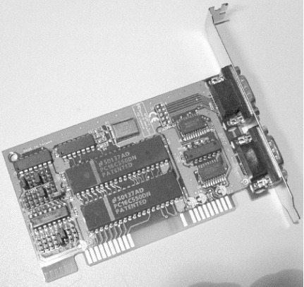
The card shown in Figure 8-2 is available from Startech.com as part number ISA2S550 and provides an extended connection into a 16-bit ISA slot to pick up IRQs 9, 10, 11, 12, and 15. Startech also offers PCI-based serial I/O and many other hard-to-find cards for many different types of PC expansion.
Tip
It is often suggested that using a USB-to-serial adapter is the way to solve COM port limitations and avoid IRQ constraints. However, USB adapters create virtual COM ports, which must in turn emulate real COM ports, up to and including using their hardware addresses and IRQ signals.
Additionally, many USB drivers create these virtual COM ports with nonstandard COM port numbers (anywhere from COM5 and much higher), which are not traditional port numbers and may not be recognized by the programs you use to communicate with a COM-port-connected device.
In a worst-case scenario, the USB-to-serial adapters, like those offered for handheld-to-PC synchronization, are known to change the COM port number they assign to themselves between reboots, leaving you to have to reconfigure the adapter or your applications to find the new randomly assigned port. Sometimes you need a real and stable COM port to get your work done.
Follow these steps to reconfigure address or IRQ settings in Windows to match the actual COM port device you are using—a physical port or a virtual one such as a USB-to-serial adapter:
Right-click My Computer and select Properties.
Select the Hardware tab, then click the Device Manager button.
In Device Manager click on the plus (+) sign to the left of Ports (COM & LPT).
Right-click the COM port entry and then select Properties.
Select the Resources tab.
Unselect the “Use automatic settings” checkbox.
Double-click either I/O Range or IRQ to make changes to these values, then click OK.
Select the Port Settings tab, then click the Advanced button to access the COM Port Number setting if you need to change the logical port number to suit the software you are using.
Click OK to exit the dialogs, restart your PC, and your port is ready to go.
Rewire Your COM Ports
Rewire an old COM port board to use available IRQs to run four ports simultaneously.
In this hack, we’ll rewire the IRQ lines of an old 8-bit COM port card to configure COM3 and COM4 ports to use IRQs 5 and 7. Rewiring older I/O cards takes a bit of skill—specifically with hand tools and a soldering iron.
Figure 8-3 shows an obvious rewire of IRQ signals. Accomplishing this rewiring required opening the circuit traces from the IRQ 3 and 4 connection “fingers,” then adding wires from the IRQ 5 and 7 “fingers” to the circuit traces that once connected to IRQs 3 and 4.
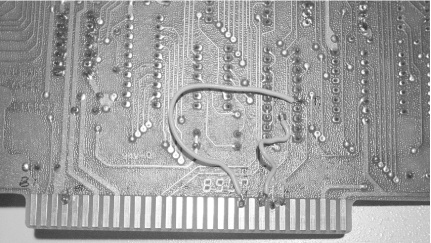
If you decide to try this at home, you need to know the connector pin information to locate the respective IRQ circuit traces, which are:
| Pin B21 = IRQ7 |
| Pin B23 = IRQ5 |
| Pin B24 = IRQ4 |
| Pin B25 = IRQ3 |
The “B” designates the component side of the circuit board, as shown in Figure 8-3. Pins are counted from the bracket (off camera to the left) towards the end of the card. Pin B21 is the 21st pin from the left.
To perform this hack, you need the following tools:
A 60-watt soldering iron or a temperature-controlled soldering iron with a small 700-800 degree tip
Solder
2 to 3 inches of 22- to 26-gauge wire
Wire cutters and strippers
An X-ACTO or similar hobby knife
With the right tools at hand, follow these steps:
Power down the computer, unplug it, and remove the card.
Locate the circuit traces that lead from pins B24 and B25 and go into circuitry on the card—most likely to a switch or jumper block. You can decide to simply leave the respective switches or jumpers in their open condition rather than cutting the copper foil traces, but you do run the risk of inadvertently closing those connections and shorting two IRQ lines together.
Cut the foil traces using the pointed end of a small hobby knife, making sure the cut is clean and all the way into the circuit board material to ensure you completely open the foil trace.
Prepare two short pieces of wire (26-gauge wire-wrap wire is the traditional circuit board mending wire of choice) as long as needed to reach from the connector pins to the switch or jumper block you traced the cut IRQ 3 and 4 lines to. Strip about 1/8” of insulation off each end and tin (wet or soak with hot molten solder) the exposed wire ends with solder as necessary.
Locate and tin the very top edge of pins B21 and B23.
Attach one end of each wire to each connector pin.
Attach the other end of each wire to the point on the switch or jumper block that was connected to the copper traces for IRQs 3 and 4.
Make sure the connections are secure: add a dab of glue or tape to hold them in place.
Install the card in your system.
Boot up your system and configure Windows or your communications software to use the new settings. Your system BIOS and Windows should recognize the new COM ports, but Windows needs a little help in its configuration because it assumes COM3 and COM4 use IRQ4 and IRQ3, respectively, which needs to be changed to reflect reality. Windows allows you to manually change the COM port configurations in Device Manager. To do this:
Launch Windows Device Manager (right-click on My Computer, click Properties, select the Hardware tab, and click Device Manager).
Locate the Ports (COM & LPT) listing and expand it.
Open the Properties dialog and select the Resources tab for each COM port in turn.
Disable the “Use automatic settings” checkbox (clear the checkmark), then choose a new configuration setting in the “Settings based on” drop-down menu. As you change the selection, notice the I/O Range and IRQ values change in the “Resource settings:” box. When these values change to I/O Range = 3E8-3EF and IRQ = 7 for the COM3 port (to match the changes you made on the I/O card), stop and click OK.
Repeat this process for COM4 until the resources indicate I/O Range = 2E8-2EF and IRQ = 5 (to match the changes you made on the I/O card), then click OK. Close Device Manager, and your new ports and Windows settings are ready for testing and use.
Boost COM Port Performance
If your PC has a COM port, tweak your state-of-the-art UAR/T chip through Windows settings.
Back in the olden days of the early PCs, getting online meant dialing in to CompuServe, Delphi, or The Source with a 300- to 1,200-baud modem, only to arrive at the legacy equivalent of Telnet—plain white characters on a green or black screen background, text menus (online servers were truly mainframes back then), and XMODEM downloads of “huge” 300 KB files. Back then, you could connect at 2,400 baud—or better yet 9,600—if your local node supported it, but this was a real challenge and a technical stress on PC serial ports. Generally, a PC built before 1990 couldn’t communicate with the outside world any faster than 9,600 bits per second (bps).
The main component that made up the serial/COM port in the PC was a component called the 8250 Universal Asynchronous Receiver/Transmitter chip (UAR/T). The 8250 was capable of transferring data at a rate of 9,600 bps, roughly 960 ASCII characters per second. In the IBM PC-AT systems, the UAR/T was upgraded to the 16450 chip, which doubled the reliable throughput to 19,200 bps.
Both of these chips generated an interrupt signal to the CPU for every character of data or control information that came across the port. This was highly inefficient and bogged down the PC to a crawl, which didn’t matter under single-tasking DOS but had a severe impact on the performance of multitasking Windows.
After becoming aware of this tremendous bottleneck, various chip makers created a new version of the UAR/T that provided 16 bytes of first-in/first-out (FIFO) data buffer, which held a chunk of data back until the buffer was full, reducing the need to interrupt the CPU significantly. The 16550 UAR/T was born. Unfortunately, the original 16550 had a design flaw: the buffer didn’t work! Very quickly, the 16550A version of the chip was released in which the buffering did work. The result was a serial/COM port that could achieve 115 kilobits-per-second (kbps) transfer rates—a whopping 11.5 kilobytes per second (8 bits for data, 2 bits for data control information). Chip maker SMC created a combined serial/COM and parallel/LPT port chip to condense three ports into one smaller chip—a great idea, but the serial port didn’t work right in some of its early production runs, so a special patch program was distributed to turn on all of the chip’s features.
Later versions of this popular UAR/T chip came out: the 16650 UAR/T with a 32-byte FIFO, the 16750 UAR/T with a 64-byte FIFO, and the 16950 UAR/T with a 128-byte FIFO. For all their speed advantages, these have never seen the light of regular PC production: except for ISDN data connections, telephone and modem technology never exceeded the 53 kbps speed barrier so there was really no need for a serial port with data throughputs of 256-512 kbps. Instead, Ethernet ports, ISDN, DSL, and cable modems served the need for high-speed data connections, while USB ports handled higher-speed peripheral devices.
In support of these different UAR/T chip communications, software makers and Microsoft had to recognize the type of UAR/T chip present and be able to configure the chip for the best possible performance. Popular programs like Procomm Plus, shareware COM-AND, and Windows 95 were able to take advantage of the newer UAR/Ts and support the old if needed. Buffered 16550 UAR/T support was invisible in DOS and later Windows-based terminal programs; they simply set the device for maximum performance and went about their business. Windows, on the other hand, held back just a bit and limited port speed and buffer use so serial communications didn’t visibly impact Windows performance.
Figure 8-4 shows the basic serial port configurations in Windows. Normally the “Bits per second:” parameter is set to 9,600, while optimum performance is achieved if the value is set to 115,200.
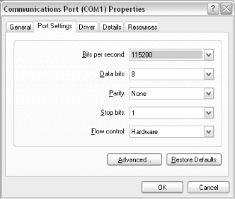
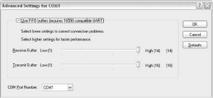
Figure 8-5 shows the advanced settings for a serial port. By default, Windows sets the receive buffer a notch lower than optimum so that communications do not disrupt overall Windows performance
Fortunately, Windows-based communications programs, from Hyperterm to Procomm Plus to the CompuServe and AOL services, could override the port speed value and set it to 38,400 or 57,600 themselves to accommodate 14.4, 28.8, and 56K modem technologies, but they did not tamper with the buffering value.
To achieve the best serial port performance, access each COM port’s Properties, select the Basic Serial Port Settings dialog (Figure 8-4) through Device Manager, set the port speed as high as possible, and then select the Advanced button to access the UAR/T buffer settings (Figure 8-5) and set both Transmit and Receive buffers to their maximum values.
New Uses for an Old Port
Select the correct LPT port settings to optimize the performance of Windows’s Direct Cable Connection and third-party file transfer applications.
Your basic line parallel port is used for more than just sending text and graphics to your printer. Iomega and others found the port useful for connecting add-on disk and tape storage devices; Traveling Software, Symantec, AlohaBob, and others found the port useful for PC-to-PC file transfers; and Microsoft and others figured out how to use the port for PC-to-PC networking.
PC-to-PC file transfers and networking require a special cross-over cable (such as the Belkin F3B207 and F3D508 series) to get the right signals connected between two PCs, as well as the installation of appropriate software or the Windows Direct Cable Connection (DCC) feature. Microsoft provides easy-to-follow directions for setting up DCC at their web site: http://support.microsoft.com/default.aspx?scid=kb;en-us;305621. DCC can be used for Windows XP’s Files and Settings Transfer feature to migrate data from an old PC to a new one, transfer applications and data with Aloha Bob’s PC Relocator [Hack #96] , and clone entire drives from one PC to another using Symantec’s GHOST [Hack #95] .
By setting the parallel port to ECP mode in the system BIOS on both PCs, a DCC connection between two PCs via parallel ports can be up to three times faster than a 10BaseT (10 megabits per second) Ethernet connection. Windows will detect mode changes in the parallel port settings and configure itself for you. Be sure you do not have any IRQ or DMA conflicts [Hack #75] or the connection may not work or will perform poorly.
Use USB for Peer-to-Peer Networking
USB’s versatility comes in handy for PC-to-PC data transfer as well as file and Internet sharing.
If you’d like to move data between systems more quickly than the parallel port allows, you can always step up to interconnecting PCs by USB. Belkin, Traveling Software, and other vendors sell USB transfer cables and accompanying software—effectively a crossover or null modem cable between two USB ports. In some cases, the cable becomes a private TCP/IP network connection and can be used for Internet connection sharing.
Using a USB-to-USB bridging cable is especially handy for systems without network adapters that need to communicate with each other in a peer-to-peer network.
A USB PC-PC interconnection cable costs about $30-40 and comes with appropriate drivers. (The cables contain USB devices that crossover the send and receive lines between PCs.) It is often packaged with software or wizards that help you establish connectivity between PCs.
Get the Most out of USB
Use separate USB ports to get the best performance out of your high-speed devices.
The USB port in your PC is designed to supply up to 12 (USB 1.1) or 480 (USB 2.0) megabits per second throughput to attached devices, but that is total throughput and must be shared with all connected devices. If you use two USB ports on your PC at the same time, it’s best to have two USB controllers, each delivering the total throughput. Although this limitation is more noticeable with the slow USB 1.1 speeds, you’ll certainly notice it if you do something I/O-intensive with USB 2.0, such as copying large files between two USB mass storage devices.
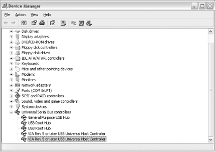
To check if you have two USB controllers, open Windows Device Manager and expand the Universal Serial Bus controllers branch in the list. If you have two separate controllers, they will be listed, as shown in Figure 8-6.
If you need to connect and use two high-speed USB devices at the same time, such as a scanner, external disk drive, video camera, or network adapter, connect them to different ports on your PC so neither one suffers from sharing bandwidth. If you need to support more than two high-speed devices operating at the same time, you will have to add a USB hub or install additional USB controllers, either with an add-in PCI card for your desktop or a PC card for your laptop. If you’re going to install a new PCI-based USB interface, get a USB 2.0-compliant card to get two upgrades in one.
To see how much bandwidth is being used on your USB ports, expand the properties of the Universal Serial Bus controllers listing in Device Manager and select the Advanced tab. As shown in Figure 8-7, you will see how much of your USB bandwidth is consumed.
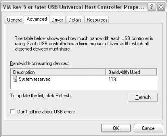
Monitoring the bandwidth used on a specific USB port can tell you if one device, such as your video camera or video-to-USB capture device, is hogging all the throughput and whether it’s time to add another separate interface to share the available bandwidth across multiple ports.
Use USB-Powered Hubs for Stability
USB ports are supposed to be able to provide up to 500 milliamps (mA) of current to power-attached devices. No single USB device is supposed to draw more than 500 mA from a USB port, and if it needs more, it is required to provide its own power source. Some devices, such as a data connection to a PDA or cell phone, may not use any power from the port, but beware that many of these cables are now used to charge these devices as well.
Those cute little two- and four-port USB hubs are handy to expand the number of devices you can connect to your port, but obviously a single device, or combination of devices, that tries to draw more than 500 mA will overload your USB port and one or more devices will stop working due to lack of power.
If your USB devices only function intermittently, it is likely that power is your problem. Running a USB web cam, charging your PDA and cell phone, and using a USB mouse at the same time might change your Universal Serial Bus into an unusable serial bus. For around $20, you can get a powered USB hub with more than enough capacity to supply multiple power-grabbing devices without a glitch. Do the math when you buy it. For example, if you get a four-port powered hub, be sure the power supply that comes with it is rated for two amperes so you can get a full 500 mA per port.
Install the Driver Before You Install the Hardware
How not to “outsmart” Plug and Play and the Windows Add New Hardware wizard.
As brilliant and helpful as the concept and implementation of Plug and Play [Hack #18] has been, it is possible to confound it. This hack is almost too simple, and all too easily overlooked: install the drivers provided with your devices before you connect the device to your computer.
Why? As you probably know, when you connect a new device to your PC, Windows starts its Add New Hardware wizard and usually prompts you to provide the location of the drivers for the device. When the wizard runs, you have three choices: locate the disk or download location for the driver and let the wizard continue to install the driver and enable the device; let the wizard try to find new the driver on its own and possibly fail; or cancel the installation.
If you locate the driver and it installs, all is well. If the wizard cannot find a driver, it disables the device, remembers that the device is unconfigured, and marks it as an Unknown Device in Windows Device Manager. This is a fairly common situation for many USB devices, especially among anxious users who expect Plug and Play to “know all” and connect their devices, without following instructions. Windows needs to have the driver information available so it can detect the device by name and associate it with the right driver.
If you don’t have the driver immediately handy but know you’ll find it eventually, go back one step and cancel the wizard. Do not let the wizard mark the device as unknown or it will be dumped in “unknown device purgatory.”
Once the device is remembered as being “unknown,” no further attempts to install a driver will be made no matter how many times you disconnect the device, restart it, or reconnect it. The only way to get out of this condition is to uninstall the device using the Device Manager, as follows:
Disconnect the device so you do not end up in a vicious circle of failed installations.
Call up Windows Device Manager and note the presence of a yellow dot with an exclamation point inside, as shown in Figure 8-8.
Right-click the Unknown Device label and select Uninstall. Then you are free to reinstall the device, but only after you have found and installed the driver for it.
Tip
Very often you can “scrounge” through Windows device listings and find an acceptable alternative or generic driver to get you going, albeit with the loss of some features. A good example is the installation of a typical HP LaserJet printer. Most LaserJet printers respond to the same Printer Control Language (PCL) command set, so you can get away with picking the older LaserJet 4 driver to print to a new LaserJet 4100.
Printers that use the Adobe PostScript (PS) language will print with almost any generic or specific PostScript driver.
As simplistic as it sounds, taking a minute to read and follow the instructions will save you several minutes, hours, or days of frustration as you try to figure out how to resolve the problem. Install the drivers first and connect the device afterwards.
This type of problem has been the curse of PCs and technology advances for years, whether or not the technology is ISA, SCSI, Plug and Play, PCI, USB, or AGP. Most add-on devices are created and sold sometime after the hardware and operating system have been sold and installed, so there is no way Windows could have a driver for the device or know it existed beforehand. Unfortunately, Windows Update does not support enough driver updates to be of much help here, so you are dependent on what ships in the box and the content of vendors’ web sites to keep your hardware up to date.
Tip
If you believe you need an updated driver for a hardware device visit the manufacturers’ web sites for the latest versions that may or may not ever make it into the Windows Update service.
In order for Windows Update to provide device drivers, the manufacturer of the device must submit their drivers to a lab for extensive testing to get Microsoft certification, and then to Microsoft for inclusion in Windows Update—an expensive and time-consuming process. You are much more likely to get the latest, greatest, and most stable driver directly from the manufacturer.
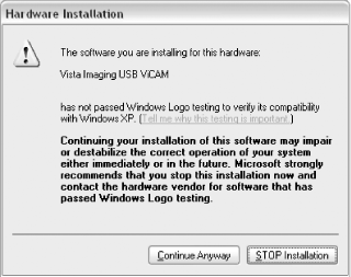
Please Continue Anyway
You’ve seen the dialog box shown in Figure 8-9 pop up during a new driver installation: “The software you are installing for this hardware: Some Cool Device has not passed Windows Logo testing to verify its compatibility with Windows XP...” Yikes! It’s enough to scare you out of hooking anything up to your PC.
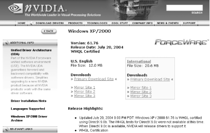
To solve this problem, locate and download a Windows-certified driver from the vendor’s web site, assuming one is available. The risk of not doing so is minimal, but using a certified driver removes an element of potential surprise and disaster that may appear later on. Certified drivers will often be flagged with the words “WHQL Certified,” as shown in Figure 8-10.
The warning dialog appears because the driver installation package did not come with a digital certificate that matches the one in Windows to let the installation process know the file was tested by a Microsoft-approved lab.
The intention is good: vendors have someone who knows the Windows environment very well review their drivers to ensure they are not consuming all the memory, stealing resources, or overwriting operating system files or other applications’ files, and then they assure the public that things are OK. Then the vendor can deliver the assurance that all is well with the program or driver in the form of a digital certificate that matches the one Microsoft provided in the operating system. This is Microsoft’s answer to the many cases of driver and program conflicts we all faced under Windows 95 and 98, when the Windows market was still relatively young and programmers ran wild trying to get cool new products into users’ hands.
The scare tactic has some legitimate basis, especially if you’re Microsoft and want hundreds of vendors to spend thousands of dollars on week-long visits to testing labs to get their wares certified as “not harmful to Windows.” However, most companies can barely afford to do some of this Windows compliance testing in their own labs, much less risk the time and money sending their products to a distant lab hoping everything will pass with flying colors. Most products do not pass Windows Logo certification the first time and may not pass at all by the strict rules of the program. Passing the certification often requires the developer to plead their case and show the testing lab how their product really does comply with sound Windows programming and operation, despite Microsoft’s rules and limitations, and ultimately get an approval by conditional and careful exemption.
Tip
Microsoft certifications or compliance with their Authenticode program are intended to ensure applications or drivers are secure by protecting the files against tampering. However, the lack of these stamps of approval does not necessarily mean that the application or driver might carry a virus, is carelessly written, or is otherwise harmful; but it also means that no one but the original vendor or their developer has reviewed and tested them.
If you have a choice, locate, download, and install certified drivers. If you do not, be prepared to remove the driver and device, and possibly even boot into Safe Mode or use System Restore to extract the offending code.
You can access System Restore through StartAll ProgramsAccessoriesSystem Tools.
Today programmers have to try really hard to screw up Windows XP and Windows Server 2003—and certainly some of them do—but a clear majority of them, especially easily recognized brand name vendors, do not. Microsoft is a little better about documenting the tools and resources developers use, and developers are more mature and their employers are much more concerned about excessive support costs and product returns than making a quick buck.
You may see the compatibility testing warning dialog during one or two of approximately 20 installations of new hardware or programs, and only in one or two out of 100 cases will there ever be a problem. Fortunately, when you continue the installation, Windows Me and XP create a System Restore Point, saving the current, working preinstallation configuration that you can go back to if something does not work correctly. If your new hardware or software is from a reputable source, go ahead and select Continue Anyway: you have Windows System Restore and likely the vendor to help get you back to good working condition.