Chapter 2. Basic System Board Setup
Introduction: Hacks #11-18
This chapter covers the things the BIOS was meant to do—detect and configure devices that interact with the core PC, basic input and output (I/O) devices, and connections to the outside world. You will also see emphasis on when it makes sense to switch from older I/O devices to new.
You’re on a mission to ensure that PCs are properly configured, and you need to be armed with the knowledge and tools to carry out that mission. If you fail, you may lose any chance of improving the performance and capabilities of your PC and all further hacks may be a waste of time.
I/O devices are either contained within the system board or are optional devices plugged into slots or external interfaces connected to the system board. Their misconfiguration can interfere with more essential functions, such as those of the disk drive, display, keyboard, and mouse.
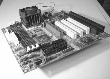
Unless you’re tinkering with a really old XT- or AT-style system board (see Figure 2-1), your PC is probably built around an all-in-one ATX-style system board with an Intel Celeron; Pentium I, II, III, or 4; or AMD Athlon or Duron CPU. It probably provides the basic I/O ports: PS/2 keyboard and mouse ports, USB ports, at least one serial/COM port , and a parallel/LPT port. If it’s a legacy-free system, it may only have USB and perhaps FireWire (IEEE 1394) ports. Various system boards include built-in sound, video, or Ethernet adapters too—lacking only a disk drive, monitor, keyboard, and mouse to be a complete PC.
With an older AT-style system, the I/O ports for your peripherals—COM, LPT, video, sound, and network—may be provided by various plug-in cards, using either 8- or 16-bit slots or perhaps even a PCI slot.
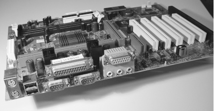
For newer systems, such as the ATX-style system board shown in Figure 2-2, I’ve foraged through the BIOS setup programs to dig up a series of hacks that, while not necessarily improving performance, can help you prevent conflicts between devices now and as you add more features into your system.
The setup features in most BIOS versions, even the OEM/name-brand PC systems, allow you to tweak the basic I/O port settings so you can enable, disable, and reconfigure ports to create a known, stable setup and work around some mistakes Plug and Play can make as you add more features into the system.
Step Away from the Legacy Device
As the Borg proclaim in many Star Trek episodes, “Resistance is futile. You will be assimilated.” So will you find emphasis on moving PC I/O capabilities and devices as far away as possible from legacy technology. ISA technology is bigger, bulkier, and fraught with more configuration complexities and conflicts than the vendors and their support people ever imagined, and it’s been more than a bit frustrating for millions of PC users as well. The best way to avoid the rest of this chapter and a lot of frustration and to gain a lot of performance and reliability is to disconnect, remove, disable, and replace all of your legacy devices with PCI, PCI-X, AGP, USB, or IEEE-1394 products.
With systems that provide enough 8- or 16-bit ISA slots (typically the black-colored edge connectors on your system board) to allow you to fill the system up with a lot of ISA devices, it is not unusual to run out of IRQs (Interrupt Request lines), limited resources that the CPU uses to address devices. Over the past few years the number of ISA slots on any given system board has decreased (often to zero) while the number of PCI slots (typically white edge connectors) has increased, and even the number of PCI slots is decreasing as more common functions (network, video, sound) have been built onto the system board. PCI devices do not have the same problems with IRQs that ISA cards have: PCI devices can share IRQs, and modern motherboards can assign IRQs dynamically (with ISA, you usually have to set a jumper on the card).
Finding any new 8- or 16-bit ISA I/O device to expand your system for more external peripherals at a computer store may be next to impossible, and you may be challenged to find documentation on how to configure any of the older boards you come across. Vendors have switched to PCI, and most peripherals have moved from using serial or parallel I/O to USB or IEEE-1394, which are beginning to make the PCI bus for external devices obsolete as well.
Expanding the I/O capabilities of a laptop computer almost certainly forces you into using products based on PC Card (formerly known as PCMCIA), or external USB or IEEE-1394 devices. Many newer laptop computers lack serial or parallel ports, forcing you to purchase USB-to-serial or USB-to-parallel adapters in order to use your older peripherals or connect to the console or terminal ports on routers, switches, and other devices.
Eventually new PCs will lack serial and parallel ports, and PCI slots will be replaced with PCI X and AGP. Many systems are being shipped without diskette drives, preferring rewritable CD-ROM and DVD drives. Even the old style 40-pin IDE drives and IDE interface is giving way to serial ATA interfaces. All this to reduce system complexity, size, cabling mazes, power requirements, cooling requirements, and hardware support burdens. Save yourself a few headaches and gain the advantages of performance and reliability with new PCI- or USB-based hardware.
Manage Devices
Take control of device configuration.
One of the basic functions of the PC’s BIOS is to identify and provide access to a variety of core components and I/O devices, whether they are embedded on the system board or plugged into an I/O card slot. Core components include the CPU, memory, internal system clocks and timers, and the I/O bus itself. Simple I/O devices supported by every BIOS include the keyboard, mouse, video adapter, I/O ports (serial, parallel, USB, and/or FireWire), and disk drive adapters. All of these devices have very predictable but limited places to be, including:
Preset and expected hardware addresses (to access and get data to or from the device)
Interrupt Request (IRQ) signals so devices can tell the CPU and programs they need attention
Direct Memory Access (DMA) request and acknowledgment signals for devices and the CPU to communicate with each other, allowing high-speed data transfers directly to and from device memory
The earlier, or legacy, BIOS dealt with the hardware as provided, and the hardware configurations were preset or manually altered using switches and jumpers. When all you had were simple I/O devices, configuring a PC was manageable but admittedly not easy for those not inclined to get inside a PC and work with wires and jumpers. As PCs got more popular, more and more nontechnical users were exposed to them, and configuring a PC started to become a major frustration and technical support nightmare for PC vendors. As technology advanced, users wanted more, faster, and better things from the PC. The simple, aging, and slow I/O devices and limitations of the PC and BIOS had to be rethought.
To be able to advance, the PC had to change, but because so many people and companies had so much invested in the PC hardware and software status quo, any new PC technology had to accommodate the old as well as the new. The goals of any technology advances were based on experience and history, leading to the following goals for PCs:
Detection, recognition, and cooperation with any ISA devices [Hack #11]
No hardware-based configuration—everything must be software-configurable
Automatic device detection, identification, and configuration, whether a new device is added or an existing one is removed
Avoidance of duplication, overlap, and conflicts with address, IRQ, and DMA signals
Notification to the operating system of hardware changes
Fast-forward through a few less-than-successful PC technology changes like the VESA Local Bus (VLB), IBM’s MicroChannel Architecture (MCA), and the Enhanced Industry Standard Architecture (EISA), and you come to the long-standing period of current technologies. These include the Peripheral Component Interconnect (PCI) I/O bus, Advanced Graphics Port (AGP), Universal Serial Bus (USB), and IEEE-1394 (aka FireWire, aka i.Link)—and more recently Serial ATA and PCI-X data buses.
None of these current technologies would have been possible or flourished if it were not for significant changes and additions to the PC BIOS—specifically, creating and adding what is known as Plug and Play capabilities.
The Plug and Play spec is available for download from Microsoft’s web site (http://download.microsoft.com/download/whistler/hwdev3/1.0/WXP/EN-US/pnpbios.exe). It makes an interesting read if you’re into technical jargon and hardware and software interactions. Amidst all of the technical and process jargon, the most salient content you will find is that Plug and Play BIOS first looks and acts like the old BIOS: it detects the presence and configuration of any legacy devices (configured by hardware switches, jumpers, or software programs that flip virtual switches in the device) in the PC and reserves those configuration settings to avoid having them used by Plug and Play devices. After discovering legacy devices, Plug and Play BIOS determines the configuration of Plug and Play devices. It evaluates what it finds for any changes to hardware settings—the addition or subtraction of devices—to determine if it should initiate automatic configuration of the new device or any previously existing devices to make sure every device has a nonconflicting configuration.
Tip
You may encounter a Plug and Play device, or its device driver, that simply insists on using the resources of an existing device, ignoring a legacy or other Plug and Play device that is using the resources.
This problem might be corrected by reconfiguring the settings for the new device with Device Manager [Hack #75] , [Hack #76] , and [Hack #77] ]. Reconfiguring a device does not take effect until the system is restarted and Windows accepts the new configuration based on updated Plug and Play BIOS data.
The Plug and Play specification does not tell you exactly how or why Plug and Play BIOS or various Plug and Play devices work. The actual implementation of Plug and Play is somewhat left up to interpretation by the programmers and engineers at dozens of vendors. Without hard and fast rules to go by, the resulting BIOS and hardware implementations can vary and affect the experiences you will have adding and configuring devices for your PC.
Tip
Plug and Play devices come in a variety of flavors, specifically, those that may only report their configuration but cannot be reconfigured, which is typical for fixed resource system board components, and those that can both report their configuration and reconfigure themselves to avoid conflicts.
There have been reports of early implementations of Plug and Play devices that supposedly reconfigure themselves but, in fact, only report their configuration and will not budge a single bit to avoid conflicts. Video cards, as a basic system device, are usually not reconfigurable and should not tell the BIOS that they are reconfigurable.
If you plug in a new PCI network adapter and suddenly find that either the network adapter is not recognized or that your PCI video card no longer works, you have probably encountered a bug in the firmware code in one of the devices. The only remedy is to find out from the manufacturer of both devices if a firmware upgrade exists to solve this problem and upgrade the adapters, or to change to another model or brand of either card.
Improving Your Odds with Plug and Play
Plug and Play is not perfect. Trying to accommodate the needs and wishes of dozens of hardware and software makers in arriving at a single set of BIOS functionality that would support and dictate the capabilities of PCs for many years could not have been an easy task. Plug and Play is quite amazing, but could do a lot more for all of us. Instead it has specific limitations in what it can do. These limitations will become apparent as you deal with the PC’s I/O system, connect devices to it, and see how operating systems deal with it all together.
Functionally, a Plug and Play BIOS pits devices against one another in a race against time to fight for available resources. A Plug and Play BIOS automatically determines which devices can change configuration, allows each device to settle on a configuration, and then stores the data to present these devices to the operating system. True Plug and Play devices are supposed to work with the BIOS to figure out device settings that do not conflict with already-configured devices and set devices (legacy devices and settings that absolutely cannot be changed, such as keyboards, mice, timers, CPU numeric processors, and disk drive interfaces). Unfortunately, some Plug and Play devices do not play nice: they do not have the ability to be reconfigured during bootup to work around already-configured devices because they are not fully compatible with Plug and Play. This happens quite often with a combination of cheap network cards and some video cards, or when mixing cheap and name-brand network cards in the same system.
If you get lucky and don’t have your network and video adapters fighting with each other, you may find that the built-in Plug and Play serial/COM ports will fight with add-in COM ports such as modems, and you will end up with a COM port set to some obscure logical device name like COM13 using nonstandard I/O addresses and an IRQ that conflicts with something else. If you are really unlucky at this high-tech roulette game, you won’t notice anything is wrong until the operating system is done loading and has found all of the new hardware and claimed it is ready for use—only to discover when you need to run a specific program that it cannot find or use the nonstandard settings. To correct these abnormalities you need to know the basics of resource configuration, which built-in devices to reconfigure, and how all devices should be properly configured. In effect, you will find times when it is necessary to override Plug and Play’s automatic settings. One example of this is demonstrated in [Hack #75] . In some cases, you may need to convince Plug and Play to question all its assumptions [Hack #18] .
Unnatural Resources
In order to hack I/O settings that have run amok, you first have to know the main players and their device addresses, IRQ settings, and DMA channels. Every I/O device in your system has a physical address to which it responds and through which it passes data. The I/O address resources for Industry Standard Architecture (ISA) or legacy devices are well known (at least to your operating system and drivers), quite limited, and typically not tampered with or changed, but it is possible to improperly configure multiple devices with the same or overlapping addresses and cause conflicts that will render those devices useless.
PCI, PCI-X, AGP, IEEE-1394, and SATA devices also have physical hardware addresses, but they are built on a much larger (32- and 64-bit) and faster data bus than ISA (8- and 16-bit) devices were. Rarely will you ever see two Plug and Play devices fighting for the same I/O address, but it can happen.
Going beyond hardware I/O addresses, we find two other resources for hardware devices: Interrupt Request (IRQ) signals and Direct Memory Address (DMA) signals. These are also well known in the realm of legacy or ISA systems and have a minor role with PCI devices. Unlike I/O addresses, which are not plentiful but of which there are enough to go around, there are only sixteen IRQ signals and eight DMA signals, called “channels.”
Of these, in a 16-bit ISA system and systems that have legacy devices but no ISA add-in slots, nine of the IRQ signals are reserved for system board and CPU functions: timers, memory, keyboard/mouse ports, numeric data processing, diskette drive, and commonly two disk drive interfaces. Some of the DMA signals are also reserved for system functions, but there is little chance of not having enough DMA signals.
This leaves a mere seven IRQ signals to be parceled out to several possible built-in or add-in I/O devices—serial/COM ports, parallel/LPT ports, sound, SCSI, network, and video adapters. At some point while expanding your system, you may run out of unique IRQ assignments for legacy devices (and some Plug and Play devices) and oddly enough find some devices must share an IRQ signal.
IRQ assignment problems are insignificant or nonexistent with PCI devices. The PCI bus is separate from the ISA bus and was designed with a lot more capabilities and possibilities, though some PCI devices do use virtual ISA IRQ assignments to maintain compatibility with DOS and DOS-based programs. It is the fact that PCI devices have to share some configurations with ISA (like a PCI-based Plug and Play modem that mimics being a COM port) to maintain compatibility with operating systems and applications that drives us to consider legacy and ISA issues and work around them.
Logically Speaking
Whether you’re adding or changing a modem card, connecting a PDA, or trying to hook up that old Iomega Zip drive so you can recover some valuable files, you’ll probably need to know something about the COM or LPT ports in your system to finish configuring the software so things work right. The configuration of the four COM ports and two LPT ports are well known because they were actually dictated in the design of the original IBM PC.
COM and LPT port numbering always seems a bit of a mystery because the COM port numbers do not follow specific pieces of hardware or settings; instead they follow a logical numbering scheme. If you only have one COM port in a system, regardless of its address or IRQ assignment, it becomes COM 1—logical because it’s the first and only port. If you add a second COM port, provided it does not use the same address as the existing COM port, it may become COM 1 or be COM 2, depending on the address used. Similar logical assignments happen with LPT ports, and you even see a hint of this with disk drive letter assignments. (Between diskette drives A: and B:, the first hard drive is C:, and so on.)
No matter what the COM port’s hardware address is, BIOS, DOS, Windows, and most programs expect that COM 1 will always use IRQ 4, and COM 2 will always use IRQ 3. Mix up the IRQ assignments and your software may have a problem communicating with the ports. You do not need to be as picky about LPT ports and their IRQ assignments in most cases, but all core system devices—clocks, timers, keyboard, mouse, and disk drive interfaces—have fixed, unchangeable IRQ settings.
To determine resource use and device conflicts under Windows, follow these steps:
Go to Start, select Control Panel, and then double-click Administrative Tools.
Under Administrative Tools, double-click Computer Management.
In the Computer Management console, select Device Manager. (You can also get here through a right-click on My Computer, selecting Properties, selecting the Hardware tab, and then clicking the Device Manager button.)
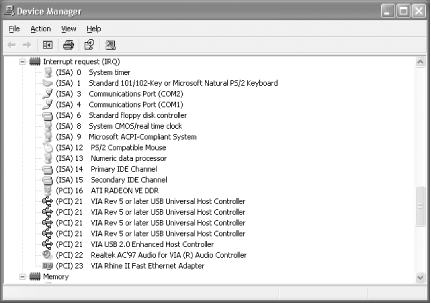
In the Device Manager, select View, then click Show Hidden Devices, select View again, and then click Resources by Type, as shown in Figure 2-3.
If you’re using Linux, you can find out a lot about your system devices
at the command prompt with a couple of simple commands. The first,
lspci, lists PCI devices:
[root@rh9-lt root]# lspci
00:00.0 Host bridge: Intel Corp. 440BX/ZX/DX - 82443BX/ZX/DX Host bridge
   (rev 03)
00:01.0 PCI bridge: Intel Corp. 440BX/ZX/DX - 82443BX/ZX/DX AGP bridge
   (rev 03)
00:02.0 CardBus bridge: Texas Instruments PCI1450 (rev 03)
00:02.1 CardBus bridge: Texas Instruments PCI1450 (rev 03)
00:03.0 Communication controller: Lucent Microelectronics WinModem 56k
   (rev 01)
00:06.0 Multimedia audio controller: Cirrus Logic CS 4614/22/24
[CrystalClear SoundFusion
Audio Accelerator] (rev 01)
00:07.0 Bridge: Intel Corp. 82371AB/EB/MB PIIX4 ISA (rev 02)
00:07.1 IDE interface: Intel Corp. 82371AB/EB/MB PIIX4 IDE (rev 01)
00:07.2 USB Controller: Intel Corp. 82371AB/EB/MB PIIX4 USB (rev 01)
00:07.3 Bridge: Intel Corp. 82371AB/EB/MB PIIX4 ACPI (rev 03)
01:00.0 VGA compatible controller: Neomagic Corporation NM2360
[MagicMedia 256ZX]
05:00.0 Ethernet controller: Xircom Cardbus Ethernet 10/100 (rev 03)
To find out which resources are being used by what devices, change to the /proc directory and inspect the ioports and interrupts files:
[root@rh9-lt root]#cd /proc[root@rh9-lt proc]#cat ioports0000-001f : dma1 0020-003f : pic1 0040-005f : timer 0060-006f : keyboard 0070-007f : rtc 0080-008f : dma page reg 00a0-00bf : pic2 00c0-00df : dma2 00f0-00ff : fpu 01f0-01f7 : ide0 03c0-03df : vga+ 03f6-03f6 : ide0 03f8-03ff : serial(auto) 0cf8-0cff : PCI conf1 4000-401f : Intel Corp. 82371AB/EB/MB PIIX4 USB 4000-401f : usb-uhci 4400-44ff : Lucent Microelectronics WinModem 56k 4500-4507 : Lucent Microelectronics WinModem 56k 4800-48ff : PCI CardBus #02 4c00-4cff : PCI CardBus #02 5000-50ff : PCI CardBus #05 5000-507f : PCI device 115d:0003 5000-507f : xircom_cb 5400-54ff : PCI CardBus #05 d000-dfff : PCI Bus #01 ef00-ef3f : Intel Corp. 82371AB/EB/MB PIIX4 ACPI efa0-efbf : Intel Corp. 82371AB/EB/MB PIIX4 ACPI fcf0-fcff : Intel Corp. 82371AB/EB/MB PIIX4 IDE fcf0-fcf7 : ide0 [root@rh9-lt proc]#cat interruptsCPU0 0: 7292143 XT-PIC timer 1: 705 XT-PIC keyboard 2: 0 XT-PIC cascade 8: 1 XT-PIC rtc 11: 9534 XT-PIC usb-uhci, Texas Instruments PCI1450, Texas Instruments PCI1450 (#2), eth0 12: 32040 XT-PIC PS/2 Mouse 14: 650116 XT-PIC ide0 NMI: 0 ERR: 80
Configure Serial Ports
Starting with a clean, industry-standard serial port configuration can save hours of headaches when you’re ready to add more devices.
If you currently or eventually will have to connect your PDA, a modem, a GPS unit, an uninterruptible power supply to protect your PC, or something else to a COM port, leave the COM port(s) enabled with a known configuration. If you know for sure how your ports are configured, it makes using them much easier.
There are several ways to tell if you have one or more COM ports on your system:
Look at the back (sometimes the front for some COMPAQ and HP systems) of your PC to see if there is a connector with nine small male pins in two rows—one of five pins, the other of four pins, surrounded by a trapezoidal or D-shaped metal shell—or a connector with 25 male pins in two rows of 13 and 12, respectively. These are known as DB-9 male and DB-25 male connectors, respectively. Only serial ports have this style of male connectors.
The presence of these connectors does not tell you specifically that there are COM port electronics wired between the connectors and your system board—these may be fillers for the addition of COM ports to a system that does not have them.
The presence of these connectors also does not tell you if they are connected to an add-in card plugged into an ISA or PCI slot or directly to COM port electronics on the system board. Only a physical inspection of the inside of your PC can tell you for sure if the connectors go anyplace and where they go.
Look into the BIOS setup program for references to serial/COM ports in the I/O port menu sections. If setup refers to COM ports and the system contains the 9- or 25-pin external connectors, chances are you do have COM ports.
It is possible your BIOS could report the existence of COM ports although you have no physical connectors for them, indicating that you are missing some cables to connect to the system board or the manufacturer never intended the ports to be used.
If you have the connectors but do not see any references to COM ports in your BIOS, then it’s likely the COM ports are provided by an add-in card.
In Windows go to the Device Manager to see if any COM ports are present. This will not tell you how the COM ports are provided, by system board or add-in card, but will tell you if a port exists and provide details about its configuration.
Use a system information or diagnostic program like SiSoft’s Sandra (http://www.sisoftware.net), Windows Device Manager [Hack #12] , or a similar program to detect and reveal the port information. These programs will not tell you how the COM ports are provided—by system board or add-in card—but will tell you if a port exists and provide details about its configuration.
If you’ve determined that you have COM port connectors and the ports are configured in the BIOS, you’ll want to set their configuration to known values so that other Plug and Play devices don’t try to use their resources later on. The proper address and IRQ settings for COM ports are listed in Table 2-1.
Port number | Address | IRQ |
COM 1 | 3F8 | 4 |
COM 2 | 2F8 | 3 |
COM 3 | 3E8 | 4 |
COM 4 | 2E8 | 3 |
Figure 2-4 shows the BIOS screens for typical Plug and Play COM ports. Auto is not the setting you want if you are concerned about establishing and maintaining a proper, known PC configuration.
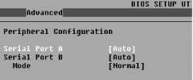
You might add other COM ports to the system configuration in the future, so you want the built-in or first serial ports in the system to be set properly for COM1 and COM2, as shown in Figure 2-5. In this example, “Serial Port A” and “Serial Port B” refer to the labeling of the physical plugs at the back of the system board. Your system board labels and settings may differ slightly. To avoid a headache in the future, change your serial port settings to those shown.
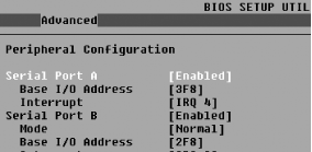
The Mode parameter typically refers to whether or not this serial interface should use a true serial I/O port or consider an available Infrared receiver/transmitter as this specific COM port. Infrared (IR) ports are rare on desktop and server systems but are quite common on circa 1995-2000 laptops. This setting should be set to Normal for most of us, unless you have a built-in IR device acting as a COM port and intend to use it. If you never intend to use your COM ports, disable or remove them entirely to leave the resources free for other devices that may need them.
Configure Parallel Ports
Set up your parallel ports in ways that accommodate your peripherals and your other expansion needs.
Although LPT ports are seldom used for much of anything (even printers, since most now use USB) these days, the occasion may arise when you need to use the port to hook up an old external disk drive to recover some important files or an old scanner to capture a document or photo, or to connect two PCs with a special transfer cable to migrate data from an old PC to a new one. Knowing the basics of your LPT ports will make these tasks easier.
Before you can use an LPT port, you need to have one, so you need to find out if you do. There are specific ways to tell if you have one or more LPT ports on your system:
Look at the back of your PC to see if there is a connector with 25 female pin holes in two rows of 13 and 12, respectively, surrounded by a trapezoidal or D-shaped metal shell. This connector is known as a DB-25 female .
Unfortunately, other types of interfaces use the same connector style—typically older SCSI ports and, rarely seen in the general PC population, connections for special test equipment.
The presence of these connectors does not tell you specifically that there are LPT port electronics wired between the connectors and your system board—these may be fillers for the addition of an LPT port later on.
The presence of these connectors also does not tell you if they are connected to an add-in card plugged into an ISA or PCI slot or directly to LPT port electronics on the system board. Only a physical inspection of the inside of your PC can tell you for sure if the connectors go anyplace and where they go.
Look into the BIOS setup program for references to parallel ports in the I/O port menu sections. If setup refers to LPT ports and the system contains the 25-pin external connectors, chances are you do have LPT ports.
It is possible your BIOS could refer to LPT ports although you have no physical connectors for them, indicating that you are missing some cables to connect to the system board or the manufacturer never intended the ports to be used.
If you have the connectors but do not see any references to LPT ports in your BIOS, then it’s likely the LPT ports are provided by an add-in card or the connectors are not parallel/LPT ports at all but have some other use.
In Windows, go to the Device Manager (My ComputerProperties Hardware) to see if any LPT ports are present. This will not tell you how the LPT ports are provided—by system board or add-in card—but will tell you if a port exists and give information about its configuration.
Use a system information or diagnostic program like SiSoft’s Sandra- (http://www.sisoftware.net), Windows Device Manager [Hack #12] , or a similar program to detect and reveal the port information. These programs will not tell you how the LPT ports are provided, by system board or add-in card, but will tell you if a port exists and information about its configuration.
If you’ve determined that you have LPT port connectors and the ports are configured in the BIOS, you’ll want to set their configuration to known values so that other Plug and Play devices don’t try to use their resources later on. The proper address and IRQ settings for LPT ports are listed in Table 2-2.
Figure 2-6 shows the BIOS screen for typical Plug and Play LPT ports. Auto is not the setting you want if you are concerned about establishing and maintaining a proper, known PC configuration.
To avoid the unknown and potential confusion in the future you should manually set the Parallel Port configuration to known values rather than Auto mode. Figure 2-7 shows a manually configured parallel port using default LPT1 values—address 378 and IRQ7—plus two other settings of note—Mode and DMA.
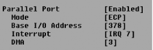
On any given system the parallel port may be capable of any of four modes of operation: the original Standard or Output-Only mode, Bi-Directional, Enhanced Parallel Port (EPP), or Enhanced Capability Port (ECP). Of these, Standard, Bi-Directional, EPP, and ECP are typically the only ones available as normal configurations for BIOS. The definitions and significance of each of these modes are as follows:
- Standard or Output-Only
Just as indicated—the port is normally used to send data out to a printer and get no data back.
- Bi-Directional
The port is capable of reading data back from a printer or other device on demand from a program intended to do so. This (or its variants, EPP and ECP) is the most common mode in use today.
- EPP
A faster variant of Bi-Directional mode with some other device status capabilities—rarely, if ever, used. ECP fixes some issues with EPP mode and adds much higher data rates and the ability to do DMA data transfers.
- ECP
An upgrade to EPP. Made the LPT port the cheapest and fastest I/O port available for such things as page scanners and external storage devices before USB hit the market.
Tip
With the availability of USB and IEEE-1394 (FireWire), ECP mode is not used much if at all. Most parallel printers, even those with programs that tell you ink or toner status, use Bi-Directional mode to free up the IRQ and DMA lines that would be used by ECP mode.
The instructions for the device you want to connect to your LPT port should indicate which mode the LPT port is required to be in for the device to work properly. Some devices do not work with EPP or ECP ports.
Configure Sound Cards
Make your sound card sing amidst the variations of limited PC resources by finding and using alternative settings.
Sound cards were among the first optional devices to be added to the old ISA PCs. When Windows 3.x became available, and with gamers demanding a more immersive experience, demand rose for a richer audio environment than the mere beeps and boops offered by the PC speaker. Users needed sound to complete “the experience.” Companies like Creative Labs and MediaVision thrust sound from PCs into users’ ears.
To accomplish this meant borrowing from emerging technologies, creating a few new technologies, and stuffing all of this into what there was of a 16- and then 32-bit PC computing platform.
The default settings for PC sound cards became address 220, IRQ5, and DMA channel 1. While there was seldom a conflict with I/O addressing, sound cards could be reconfigured to use an IRQ other than 5 and a DMA channel other than 1 to avoid other devices that could be present in the system. The DMA channel was needed to avoid stutter and skipping of data streams.
The most common symptom of a misconfigured sound card is a stuttering or choppy effect to otherwise smoothly streaming sounds. If Plug and Play is not solving a conflict and the sound card supports alternative configurations, try changing the IRQ to 7, 10, 11, or 15, or the DMA channel to 3 or 5.
You can determine the settings of your present sound card configuration using Windows Device Manager [Hack #12] or a program like SiSoft Sandra, which will detect and report on all of the I/O devices present.
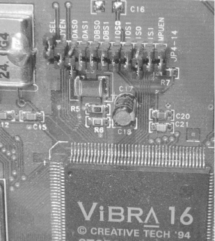
Be aware that a sound cards needs consistent, exclusive access to IRQ and DMA resources, so these resources cannot be shared with other devices. If you have an ISA-based sound card, look for the jumpers on the card, as in Figure 2-8, or use the configuration software provided to set the card for the generally accepted address (220), IRQ (5), and DMA channel (3 or 5). If you are using an ISA sound card and cannot configure it with nonconflicting settings, upgrade to a PCI-based card to avoid any ISA resource conflicts and gain better sound card performance and fidelity in the process.
Configure SCSI Host Adapters
Accommodate SCSI host adapters with nonconflicting configurations.
A SCSI interface is one of the best ways to add lots of devices—hard drives, CD-ROM or DVD drives, cartridge or tape drives, even some of the high-end graphics scanners—to your PC without using up a lot of resources. Very fast SCSI adapters and hard drives are used in servers, and most high-capacity server-grade backup tape systems use the SCSI interface because SCSI is simply faster and allows for more drive configurations like RAID.
Because of the performance offered by SCSI host adapters, you should have at least a PCI card. ISA cards are simply incapable of supporting the speeds required by today’s SCSI drives.
Most SCSI adapters are readily identified and their configurations determined and reported by Windows Device Manager and readily available PC system information programs.
Tip
Some of you may still be using 16-bit ISA SCSI adapters. As with the sound card, if you cannot configure the system to provide the host adapter with exclusive uninterrupted access to IRQ and DMA resources, an upgrade to a PCI-based adapter is your only solution, and you’ll get a huge performance boost as well.
A SCSI host adapter may contain User BIOS, so adding a SCSI host adapter to your system might require you to enable scanning the User BIOS Region of memory [Hack #4] .
IEEE-1394
As a means of connecting external devices, SCSI has been great for scanners and assorted storage devices, but it has not been forgiving or flexible in cable lengths nor as fast as newer technologies. Save SCSI for internal storage devices and high-performance server disk drive arrays, but upgrade your external peripherals—scanners, add-on and portable storage devices—to either USB 2.0 or IEEE-1394 (aka FireWire, aka i.Link). With USB or IEEE-1394, you also get the capability to add many more and different devices such as digital cameras, video recorders, printers, business card readers, SMART cards, and a variety of flash memory readers.
Configure Network Cards
Give your network card the resources it needs to get and keep your LAN and Internet traffic flowing smoothly.
Network cards are another enhancement to PCs that had to be squeezed in to the limits of old legacy I/O systems. Because networking usually requires a fast, steady stream of data, it is important that network interface cards have unique and exclusive use of address and IRQ resources. Symptoms of conflicts include the inability to obtain a network address or log on to a server, or poor data transfer performance.
The most successful implementations of early 8- and 16-bit network cards in practice used addresses 280 or 340 and IRQ5 (8-bit systems) or IRQ10 (16-bit systems), depending on the presence or absence of a sound card using IRQ5.
Determining the presence, type, and configuration of older network cards is not well supported in most diagnostic and system information programs. Instead you may have to rely on reading the jumper settings or using a configuration program meant specifically for your network adapter.
Warning
If you need Gigabit Ethernet (1000BaseT), you should use a motherboard that has it built in. If you install a 1000BaseT PCI card, it will likely saturate the PCI bus, leaving no bandwidth for other PCI cards. Onboard 1000BaseT uses a separate bus to talk to the CPU and memory.
Today, with PCI and Plug and Play, you seldom have to concern yourself with these issues. Nevertheless, knowing the commonly available configurations is useful should you ever have to configure the drivers and software for a LAN card to work in DOS, which often cannot use PCI net cards because the vendors may not provide DOS drivers for them.
Warning
Although well published in IBM specifications, address 300 was “reserved” for use by IBM and prototype devices and recognized as such in many versions of BIOS. IBM even offered a plug-in card that used address 300 for others to develop new products around.
Older ISA network cards may be set for address 300, which can cause problems for some older applications. Avoid using address 300 for anything.
Reeducate Plug and Play
The Microsoft Windows Plug and Play BIOS extension generally knows when a new device is installed, as you can see in Microsoft Windows when a “New hardware found” dialog appears, but it doesn’t know if you’ve changed the configuration of a device through its configuration/setup program or using Windows Device Manager.
It is possible, depending on the capabilities of the respective device drivers (usually for PCI network and SCSI cards), to reconfigure an I/O device through Device Manager. This reconfiguration is not dynamic: Windows won’t really know about it until Plug and Play BIOS tells it things have changed. That only happens at bootup, and sometimes only if the BIOS is told to look for the change. Merely changing a device’s internal configuration does not constitute a new or removed device in Plug and Play’s “mind,” and it never gets it without some help.
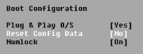
To tell Plug and Play that things have changed by adding or removing an I/O device, or by “soft” changes you made within Windows, you have to reboot your system, enter the BIOS setup, and then force Plug and Play to reassess the system configuration. This gets the BIOS to reconfigure the system properly, and informs the operating system of the changes.
Reeducating Plug and Play is done by a parameter most often named “Reset Configuration Data” or “Reset NVRAM” (non-volatile RAM). NVRAM is an area of memory on the system board that stores Plug and Play data. Make sure that Plug and Play OS is set to Yes (provided you have a Plug and Play-compliant operating system, such as Windows), set the Reset value to Yes, and then restart your PC. The BIOS will reevaluate the system configuration, store any new data, and make it available to the operating system (see Figure 2-9).