Chapter 6. Configuring and Troubleshooting IP Multicast Routing
• Configuring IP Multicast Routing—This section presents the basics of configuring both PIM-DM and PIM-SM using Cisco IOS Software and presents case studies to further understand the configuration of these protocols.
• Troubleshooting IP Multicast Routing—This section examines some of the tools available for troubleshooting IP multicast with Cisco IOS Software and provides some troubleshooting tips.
You examined various IP multicast routing protocols in Chapter 5, "Introduction to IP Multicast Routing," and you learned that the protocol of choice for Cisco and for most router vendors presently is PIM, whether dense mode or sparse mode. Now that you have an understanding of the basics of PIM operation, this chapter looks at the procedures to configure and troubleshoot both PIM-DM and PIM-SM using Cisco IOS Software.
Configuring IP Multicast Routing
Before you can configure a particular IP multicast routing protocol, you must set up the router for general, protocol-neutral multicast routing.
Note
"Protocol-independent" would be a better term than "protocol-neutral," but it would cause confusion in light of PIM.
Example 6-1 shows a configuration containing some of the commands you might use. Out of all the commands shown, ip multicast-routing is the only required one. Just as the default (and therefore hidden) ip routing enables unicast IP routing, this command enables the support of all IP multicast routing functions.
Example 6-1 The Command ip multicast-routing Is Required to Enable Multicast Routing Support; Other Commands in This Basic Configuration Might Be Required by Specific Implementations
version 12.1
!
hostname Stovepipe
!
ip multicast-routing
ip dvmrp route-limit 20000
!
interface Ethernet0
ip address 172.17.1.1 255.255.255.0
ip igmp version 1
!
interface Ethernet1
ip address 172.17.2.1 255.255.255.0
ip cgmp
!
interface Serial0
ip address 172.18.1.254 255.255.255.252
no ip mroute-cache
!
interface TokenRing0
ip address 172.16.2.1 255.255.255.0
ip multicast use-functional
ring-speed 16
!
interface TokenRing1
ip address 172.16.1.1 255.255.255.0
ring-speed 16
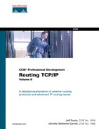
Of some interest in this configuration is the fact that there are no commands evident enabling Internet Group Management Protocol (IGMP). When IP multicast routing is enabled on the router, IGMPv2 is automatically enabled on the LAN interfaces. The only IGMP command in this configuration is ip igmp version on interface E0, changing the default to IGMPv1. Table 6-1 lists all the IGMP commands that change the default values in a given interface. Other IGMP commands are demonstrated later in this chapter.
Table 6-1 IGMP Interface Commands
The configuration of interface E1 in Example 6-1 includes the ip cgmp command, which causes Cisco Group Management Protocol (CGMP) messages to be originated for an attached Catalyst switch. Another option is ip cgmp proxy, which can be used when there are other routers on the subnet that are not CGMP-capable. This command tells the router to advertise those non-CGMP routers in its CGMP messages. If you configure a Cisco router as a CGMP proxy, you must ensure that that router is elected as the IGMP querier.
The next command of interest in Example 6-1 is no ip mroute-cache on S0. This command disables fast switching of IP multicast packets in the same way that no ip route-cache disables fast switching of unicast IP packets. You would disable the fast switching of multicast IP packets for the same reasons you would disable fast switching of unicast packets—for example, to enable per-packet load sharing across parallel paths rather than per-destination load sharing.
The configuration of interface TO0 includes the ip multicast use-functional command, whereas the configuration of TO1 does not. The result is that TO0 maps multicast IP packets to the Token Ring functional address 0xC000.0004.0000. TO1, on the other hand, maps multicast IP addresses to the broadcast address 0xFFFF.FFFF.FFFF.
Case Study: Configuring Protocol-Independent Multicast, Dense Mode (PIM-DM)
After you have enabled IP multicast routing on a Cisco router, you can very simply enable PIM-DM by adding the command ip pim dense-mode to all the router’s interfaces. Figure 6-1 shows a simple PIM-DM topology, and Example 6-2 shows the configuration of router Porkpie. The other router configurations are similar to that of Porkpie.
Figure 6-1 This Topology Is Used to Demonstrate Basic PIM-DM Functionality
Two important considerations when configuring PIM-DM are reflected in Example 6-2. The first and most obvious is that a unicast routing protocol—in this case, OSPF—must be running. Without it, PIM has no mechanism for determining the Reverse Path Forwarding (RPF) interface. The second consideration can be observed by comparing the configuration in Example 6-2 with the topology diagram in Figure 6-1. When configuring PIM, the protocol should be enabled on every interface. Otherwise, you run the risk of inadvertent RPF failures.
Example 6-2 The ip pim dense-mode Command Enables PIM-DM on an Interface
hostname Porkpie
!
ip multicast-routing
!
interface Ethernet0
ip address 10.1.2.1 255.255.255.0
ip pim dense-mode
ip cgmp
!
interface Serial1
no ip address
encapsulation frame-relay
no ip mroute-cache
!
interface Serial1.605 point-to-point
description PVC to Fedora
ip address 10.2.4.1 255.255.255.0
ip pim dense-mode
no ip mroute-cache
frame-relay interface-dlci 605
!
interface Serial1.609 point-to-point
description PVC to Stetson
ip address 10.2.3.2 255.255.255.0
ip pim dense-mode
no ip mroute-cache
frame-relay interface-dlci 609
!
router ospf 1
network 10.0.0.0 0.255.255.255 area 0
!
Example 6-3 shows Porkpie’s mroute entry for group 228.13.20.216 after source 10.1.1.88 has begun transmitting, and after member 10.1.2.113 has joined. The PIM-DM section of Chapter 5 showed only the (S, G) mroute entry in its examples for the sake of clarity. In reality, a (*, G) entry is created in addition to the (S, G). The (*, G) entry is not part of PIM-DM specification and is not used for packet forwarding. Rather, Cisco IOS Software creates the entry as a "parent" data structure of (S, G). All interfaces connected to PIM neighbors, and all interfaces with directly connected group members, are added to the outgoing interface list of the (*, G) entry. The incoming interface list of this entry, when only PIM-DM is running, is always empty. The incoming and outgoing interfaces in the (S, G) entry are then taken from this list.
Note
Cisco IOS Software Release 12.1 was released during the initial writing of this chapter and was installed on the demonstration routers. As a result, you will notice some differences in the field formats of commands such as show ip mroute and show ip route from earlier chapters.
Example 6-3 Porkpie’s mroute Entry for Group 228.13.20.21
Porkpie#show ip mroute 228.13.20.216
IP Multicast Routing Table
Flags: D - Dense, S - Sparse, C - Connected, L - Local, P - Pruned
R - RP-bit set, F - Register flag, T - SPT-bit set, J - Join SPT
M - MSDP created entry, X - Proxy Join Timer Running
A - Advertised via MSDP
Outgoing interface flags: H - Hardware switched
Timers: Uptime/Expires
Interface state: Interface, Next-Hop or VCD, State/Mode
(*, 228.13.20.216), 20:06:06/00:02:59, RP 0.0.0.0, flags: DJC
Incoming interface: Null, RPF nbr 0.0.0.0
Outgoing interface list:
Ethernet0, Forward/Dense, 20:05:25/00:00:00
Serial1.609, Forward/Dense, 00:03:32/00:00:00
Serial1.605, Forward/Dense, 00:03:32/00:00:00
(10.1.1.88, 228.13.20.216), 00:03:21/00:02:59, flags: CT
Incoming interface: Serial1.605, RPF nbr 10.2.4.2
Outgoing interface list:
Ethernet0, Forward/Dense, 00:03:21/00:00:00
Serial1.609, Prune/Dense, 00:03:21/00:00:03
Porkpie#
In Example 6-3, you can see that E0, S1.609, and S1.605 are on the (*, G) outgoing interface list. S1.605 is then entered as the RPF interface in the (S, G) entry, and packets are being forwarded out E0. S1.609 is also on the outgoing list, but is pruned.
As discussed in Chapter 5, PIM (and any other multicast protocol that uses RPF checks) can have only one incoming interface. Example 6-4 shows Porkpie’s unicast routing table. There are two equal-cost paths to source subnet 10.1.1.0/24, so PIM breaks the tie by choosing the interface to the neighbor with the numerically higher IP address as the RPF interface. In Example 6-4, this address is 10.2.4.2 on interface S1.605. A look back at Example 6-3 verifies that this interface is on the incoming interface list.
Example 6-4 Porkpie’s Unicast Routing Table
Porkpie#show ip route
Codes: C - connected, S - static, I - IGRP, R - RIP, M - mobile, B - BGP
D - EIGRP, EX - EIGRP external, O - OSPF, IA - OSPF inter area
N1 - OSPF NSSA external type 1, N2 - OSPF NSSA external type 2
E1 - OSPF external type 1, E2 - OSPF external type 2, E - EGP
i - IS-IS, L1 - IS-IS level-1, L2 - IS-IS level-2, ia - IS-IS inter area
* - candidate default, U - per-user route, o - ODR
P - periodic downloaded static route
Gateway of last resort is not set
10.0.0.0/24 is subnetted, 6 subnets
O 10.2.1.0 [110/128] via 10.2.4.2, 00:15:07, Serial1.605
C 10.1.2.0 is directly connected, Ethernet0
O 10.2.2.0 [110/128] via 10.2.3.1, 00:15:07, Serial1.609
O 10.1.1.0 [110/138] via 10.2.4.2, 00:15:07, Serial1.605
[110/138] via 10.2.3.1, 00:15:07, Serial1.609
C 10.2.3.0 is directly connected, Serial1.609
C 10.2.4.0 is directly connected, Serial1.605
Porkpie#
In Figure 6-2, another router has been added to the internetwork. This router, Bowler, is connected to the Ethernet switch and so is sharing a multiaccess link with Porkpie. The rules for IGMP queriers, PIM-designated routers, and PIM forwarders discussed in Chapter 5 all come into play here:
Figure 6-2 Router Bowler Has Joined the Internetwork of Figure 6-1; Bowler, Porkpie, and the Group Member Are Connected to a Multiaccess Network Through the Catalyst Switch
• The router with the lowest IP address becomes the IGMPv2 querier.
• The router with the highest IP address becomes the PIM-designated router. The DR is important only when IGMPv1 is running on the subnet.
• The PIM forwarder is the router whose route to the source has the lowest administrative distance. If the administrative distances are equal, the router whose route to the source has the lowest metric is the forwarder. If both the administrative distances and the metrics are equal, the router with the highest IP address is the forwarder.
Example 6-5 shows that the IGMPv2 querier and PIM-designated router rules have been applied. Porkpie (10.1.2.1) has the lower IP address on the subnet, so it is the IGMP querier. Bowler (10.2.1.25) has the higher IP address, so it is the designated router. Porkpie and Bowler are both running IGMPv2, so the DR has no importance here.
Example 6-5 Porkpie (10.1.2.1) Is the IGMP Querier, but Bowler Is the PIM Designated Route
Bowler#show ip igmp interface ethernet 0
Ethernet0 is up, line protocol is up
Internet address is 10.1.2.25/24
IGMP is enabled on interface
Current IGMP version is 2
CGMP is enabled on interface
IGMP query interval is 60 seconds
IGMP querier timeout is 120 seconds
IGMP max query response time is 10 seconds
Last member query response interval is 1000 ms
Inbound IGMP access group is not set
IGMP activity: 6 joins, 2 leaves
Multicast routing is enabled on interface
Multicast TTL threshold is 0
Multicast designated router (DR) is 10.1.2.25 (this system)
IGMP querying router is 10.1.2.1
No multicast groups joined
Bowler#
Example 6-6 shows the unicast routes to source subnet 10.1.1.0/24 at both Porkpie and Bowler. Knowing that the internetwork of Figure 6-2 is running OSPF exclusively, it comes as no surprise that both routes have an administrative distance of 110. You also can readily see that both routes have an OSPF cost of 138. Therefore, the PIM forwarder for (10.1.1.88, 228.13.20.216) on the attached subnet 10.1.2.0/24 is the router with the highest IP address: Bowler. Example 6-7 proves it. Comparing Porkpie’s (S, G) entry with the one in Example 6-3, notice that interface E0 has now been pruned. Bowler’s E0 interface is in forward mode, indicating that it is now forwarding the group traffic onto the subnet.
Example 6-6 The Unicast Routes to Source Subnet 10.1.1.0/24 in Porkpie and Bowler Have Equal Administrative Distances and Metrics; Therefore, the Router with the Highest IP Address Will Be the PIM Forwarder for Subnet 10.1.2.0/24
Porkpie#show ip route 10.1.1.0
Routing entry for 10.1.1.0/24
Known via "ospf 1", distance 110, metric 138, type intra area
Redistributing via ospf 1
Last update from 10.2.3.1 on Serial1.609, 01:01:30 ago
Routing Descriptor Blocks:
* 10.2.4.2, from 10.1.1.1, 01:01:30 ago, via Serial1.605
Route metric is 138, traffic share count is 1
10.2.3.1, from 10.1.1.1, 01:01:30 ago, via Serial1.609
Route metric is 138, traffic share count is 1
Porkpie#
_______________________________________________________________________
Bowler#show ip route 10.1.1.0
Routing entry for 10.1.1.0/24
Known via "ospf 1", distance 110, metric 138, type intra area
Redistributing via ospf 1
Last update from 10.2.5.2 on Serial1.705, 01:02:22 ago
Routing Descriptor Blocks:
* 10.2.5.2, from 10.1.1.1, 01:02:22 ago, via Serial1.705
Route metric is 138, traffic share count is 1
Bowler#
Example 6-7 Comparing the mroutes for (10.1.1.88, 228.13.20.216) Shows that Bowler Is Now the Forwarder for the Group onto Subnet 10.1.2.0/24
Porkpie#show ip mroute 228.13.20.216
IP Multicast Routing Table
Flags: D - Dense, S - Sparse, C - Connected, L - Local, P - Pruned
R - RP-bit set, F - Register flag, T - SPT-bit set, J - Join SPT
M - MSDP created entry, X - Proxy Join Timer Running
A - Advertised via MSDP
Outgoing interface flags: H - Hardware switched
Timers: Uptime/Expires
Interface state: Interface, Next-Hop or VCD, State/Mode
(*, 228.13.20.216), 23:51:13/00:02:59, RP 0.0.0.0, flags: DJC
Incoming interface: Null, RPF nbr 0.0.0.0
Outgoing interface list:
Serial1.609, Forward/Dense, 03:48:39/00:00:00
Serial1.605, Forward/Dense, 03:48:39/00:00:00
Ethernet0, Forward/Dense, 01:18:18/00:00:00
(10.1.1.88, 228.13.20.216), 00:03:06/00:02:53, flags: PCT
Incoming interface: Serial1.605, RPF nbr 10.2.4.2
Outgoing interface list:
Serial1.609, Prune/Dense, 00:03:06/00:00:18
Ethernet0, Prune/Dense, 00:03:06/00:02:53
Porkpie#
_______________________________________________________________________
Bowler#show ip mroute 228.13.20.216
IP Multicast Routing Table
Flags: D - Dense, S - Sparse, C - Connected, L - Local, P - Pruned
R - RP-bit set, F - Register flag, T - SPT-bit set, J - Join SPT
M - MSDP created entry, X - Proxy Join Timer Running
A - Advertised via MSDP
Outgoing interface flags: H - Hardware switched
Timers: Uptime/Expires
Interface state: Interface, Next-Hop or VCD, State/Mode
(*, 228.13.20.216), 01:47:12/00:02:59, RP 0.0.0.0, flags: DJC
Incoming interface: Null, RPF nbr 0.0.0.0
Outgoing interface list:
Ethernet0, Forward/Dense, 01:26:34/00:00:00
Serial1.705, Forward/Dense, 01:47:12/00:00:00
(10.1.1.88, 228.13.20.216), 01:27:43/00:02:59, flags: CTA
Incoming interface: Serial1.705, RPF nbr 10.2.5.2
Outgoing interface list:
Ethernet0, Forward/Dense, 01:26:34/00:00:00
Bowler#
Interestingly, Porkpie is querying for group members on the subnet, while Bowler is forwarding the multicast packets for group 228.13.20.216. Reviewing the rules for IGMPv2 in Chapter 5, there is no conflict. Queries from Porkpie result in IGMP Membership Reports from the group member, addressed to the group address. Bowler hears the Membership Report and begins forwarding the group traffic. If the member wants to leave the group, it sends IGMP Leave messages addressed to the All Multicast Routers address 224.0.0.2, as illustrated by Example 6-8, which are also heard by Bowler.
Example 6-8 Although Porkpie (10.1.2.1) Is the IGMP Querier, Bowler Still Hears the IGMP Leave Message from the Attached Group Member; as the Forwarder for This Group, It Deletes the Interface from the Outgoing Interface List for the Group
Bowler#debug ip igmp
IGMP debugging is on
Bowler#
IGMP: Received Leave from 10.1.2.113 (Ethernet0) for 228.13.20.216
IGMP: Received v2 Query from 10.1.2.1 (Ethernet0)
IGMP: Received v2 Query from 10.1.2.1 (Ethernet0)
IGMP: Deleting 228.13.20.216 on Ethernet0
Bowler#
Referring back to Example 6-5, show ip igmp interface shows that Bowler’s E0 is using the default IGMP query interval of 60 seconds and the default IGMP querier timeout interval of 120 seconds. Porkpie is using the same defaults. The debugging messages with time stamps in Example 6-9 show these timers in action. The first three messages show Porkpie faithfully sending an IGMP query every 60 seconds. But then something happens and the queries stop. The fourth and fifth messages show that at 120 seconds, Bowler takes over as querier and immediately sends a query of its own. Subsequent queries are then sent at 60-second intervals. The last two messages show that Porkpie has returned and is again sending queries. Because that router has a lower IP address, Bowler recognizes Porkpie as the querier and goes silent.
Example 6-9 Debugging Is Used to Show What Happens When the IGMP Querier Fails and Then Returns
Bowler#debug ip igmp
IGMP debugging is on
Bowler#
*Mar 5 23:41:36.318: IGMP: Received v2 Query from 10.1.2.1 (Ethernet0)
*Mar 5 23:42:36.370: IGMP: Received v2 Query from 10.1.2.1 (Ethernet0)
*Mar 5 23:43:36.422: IGMP: Received v2 Query from 10.1.2.1 (Ethernet0)
*Mar 5 23:45:36.566: IGMP: Previous querier timed out, v2 querier for Ethernet0 is
this system
*Mar 5 23:45:36.570: IGMP: Send v2 Query on Ethernet0 to 224.0.0.1
*Mar 5 23:46:05.602: IGMP: Send v2 Query on Ethernet0 to 224.0.0.1
*Mar 5 23:47:05.654: IGMP: Send v2 Query on Ethernet0 to 224.0.0.1
*Mar 5 23:48:05.706: IGMP: Send v2 Query on Ethernet0 to 224.0.0.1
*Mar 5 23:48:36.698: IGMP: Received v2 Query from 10.1.2.1 (Ethernet0)
*Mar 5 23:49:36.742: IGMP: Received v2 Query from 10.1.2.1 (Ethernet0)
Bowler#
Remember from Chapter 5 that PIM sends hellos to its neighbors by default every 30 seconds, and the holdtime is 3.5 times the hello interval. If a hello is not heard from a neighbor within the holdtime, the neighbor is declared dead. This final example begins with both Bowler and Porkpie online and with Bowler forwarding packets onto the Ethernet for group 228.13.20.216. Example 6-10 shows what happens when Bowler fails.
Example 6-10 Porkpie Takes Over as PIM Forwarder for Group 228.13.20.216 After Failing to Hear Any PIM Hellos from Bowler for the Prescribed Holdtime
Porkpie#debug ip pim 228.13.20.216
PIM debugging is on
Porkpie#
PIM: Neighbor 10.1.2.25 (Ethernet0) timed out
PIM: Changing DR for Ethernet0, from 10.1.2.25 to 10.1.2.1 (this system)
PIM: Building Graft message for 228.13.20.216, Serial1.609: no entries
PIM: Building Graft message for 228.13.20.216, Serial1.605: no entries
PIM: Building Graft message for 228.13.20.216, Ethernet0: no entries
Porkpie#
Porkpie has not heard a hello from Bowler within the holdtime, and it knows that it must take over the PIM forwarder duties. It assumes the role of the DR and sends PIM Graft messages to its neighbors. Comparing Porkpie’s entry for (10.1.1.88, 228.13.20.216) in Example 6-11 with that at the top of Example 6-7, Porkpie is now forwarding the multicast packets onto the Ethernet whereas it had pruned the interface before becoming the forwarder. Notice also that the pruned flag, present in the entry in Example 6-7, is no longer in the entry in Example 6-11.
Example 6-11 After the Failure of Bowler, Porkpie Is Forwarding Group Traffic onto the Ethernet
Porkpie#show ip mroute 228.13.20.216
IP Multicast Routing Table
Flags: D - Dense, S - Sparse, C - Connected, L - Local, P - Pruned
R - RP-bit set, F - Register flag, T - SPT-bit set, J - Join SPT
M - MSDP created entry, X - Proxy Join Timer Running
A - Advertised via MSDP
Outgoing interface flags: H - Hardware switched
Timers: Uptime/Expires
Interface state: Interface, Next-Hop or VCD, State/Mode
(*, 228.13.20.216), 1d01h/00:02:59, RP 0.0.0.0, flags: DJC
Incoming interface: Null, RPF nbr 0.0.0.0
Outgoing interface list:
Serial1.609, Forward/Dense, 05:16:35/00:00:00
Serial1.605, Forward/Dense, 05:16:35/00:00:00
Ethernet0, Forward/Dense, 00:06:14/00:00:00
(10.1.1.88, 228.13.20.216), 00:23:10/00:02:59, flags: CT
Incoming interface: Serial1.605, RPF nbr 10.2.4.2
Outgoing interface list:
Serial1.609, Prune/Dense, 00:23:10/00:01:44
Ethernet0, Forward/Dense, 00:06:14/00:00:00
Porkpie#
Configuring Protocol-Independent Multicast, Sparse Mode (PIM-SM)
It is probably obvious to you, after seeing the configuration statement for enabling PIM-DM on an interface, how PIM-SM is enabled. It is accomplished, quite simply, by using the ip pim sparse-mode command. This much of the configuration of PIM-SM is uninteresting and requires no standalone examples. The unique requirement of PIM-SM, and the more interesting aspect of its configuration, is the identification of the rendezvous points (RPs). You learned in Chapter 5 that RPs can be statically configured, or they can be dynamically discovered using either Cisco’s Auto-RP or the open-standard bootstrap protocol. The following case studies demonstrate all three methods.
Case Study: Statically Configuring the RP
Figure 6-3 is the same internetwork you have been observing in this chapter, but now the routers are configured to run PIM-SM. Stetson has been chosen as the RP, and all routers are statically configured with that information. The illustration shows that Stetson’s RP address is 10.224.1.1. This address can exist on any interface, as long as it is advertised by the unicast routing protocol so that the other routers know how to reach it. In practice, you should use the loopback interface. A minor reason for this is so that the RP address can be more easily managed, but the major reason is so that the RP address is not linked to any physical interface that might fail. This is the same reason that the loopback interface is recommended for IBGP peering endpoints.
Figure 6-3 The Internetwork Is Now Running PIM-SM, with the RP Located at 10.224.1.1
Example 6-12 shows Bowler’s configuration. Notice that the interfaces that were configured for dense mode are now configured for sparse mode.
Example 6-12 The Configuration of Bowler in Figure 6-3
hostname Bowler
!
ip multicast-routing
!
interface Ethernet0
ip address 10.1.2.25 255.255.255.0
ip pim sparse-mode
ip cgmp
!
interface Serial1
no ip address
encapsulation frame-relay
!
interface Serial1.705 point-to-point
description PVC to Fedora
ip address 10.2.5.1 255.255.255.0
ip pim sparse-mode
no ip mroute-cache
frame-relay interface-dlci 705
!
router ospf 1
network 10.0.0.0 0.255.255.255 area 0
!
ip pim rp-address 10.224.1.1
!
The other point of interest in Example 6-12 is the command ip pim rp-address 10.224.1.1, which tells the router where to find the RP. When statically configuring the RP, all routers with attached group sources or members must have such a statement, in order for them to know where the RP is. Note that Stetson’s loopback interface does not itself have to have PIM running on it, as indicated in Example 6-13. No PIM functionality is required of the interface, other than providing the RP address. That address is advertised to the internetwork by OSPF. However, the ip pim rp-address 10.224.1.1 statement is present in the configuration, even though there are no attached sources or group members. The reason for this statement on this router, of course, is so that the router knows that it is the RP. In practice, it is wise to statically configure the RP address on all routers in the internetwork. It won’t hurt if it isn’t needed, and it prevents an accidentally missing statement where it is needed.
Example 6-13 The Configuration of Stetson, the RP, in Figure 6-3
hostname Stetson
!
ip multicast-routing
!
interface Loopback0
ip address 10.224.1.1 255.255.255.255
!
interface Serial1
no ip address
encapsulation frame-relay
!
interface Serial1.903 point-to-point
description PVC to R3
ip address 10.2.2.2 255.255.255.0
ip pim sparse-mode
frame-relay interface-dlci 903
!
interface Serial1.906 point-to-point
description PVC to 906
ip address 10.2.3.1 255.255.255.0
ip pim sparse-mode
frame-relay interface-dlci 906
!
router ospf 1
network 10.0.0.0 0.255.255.255 area 0
!
ip pim rp-address 10.224.1.1
In the PIM-DM section, you compared the mroute entries for group 228.13.20.216 in Porkpie and Bowler. The significance of the entries is that the routers share an Ethernet subnet with a group member, so issues such as IGMP querying and PIM forwarding arise. Example 6-14 again compares the two routers’ mroute entries for the group. The entries here appear a little more ambiguous than the dense-mode entries in Example 6-7. For example, Porkpie’s (*, G) entry shows E0 on the outgoing interface list and in forwarding state. The outgoing interface list of its (S, G) entry is empty. At Bowler, however, E0 is on the incoming interface list of the (*, G) entry, and the entry’s outgoing interface list is empty. And E0 is on the outgoing interface list of the (S, G) entry and in forwarding state. What router is actually forwarding the group packets?
Example 6-14 Comparing the mroute Entries for Group 228.13.20.216 at Porkpie and Bowler
Porkpie#show ip mroute 228.13.20.216
IP Multicast Routing Table
Flags: D - Dense, S - Sparse, C - Connected, L - Local, P - Pruned
R - RP-bit set, F - Register flag, T - SPT-bit set, J - Join SPT
M - MSDP created entry, X - Proxy Join Timer Running
A - Advertised via MSDP
Outgoing interface flags: H - Hardware switched
Timers: Uptime/Expires
Interface state: Interface, Next-Hop or VCD, State/Mode
(*, 228.13.20.216), 1d22h/00:02:59, RP 10.224.1.1, flags: SJC
Incoming interface: Serial1.609, RPF nbr 10.2.3.1
Outgoing interface list:
Ethernet0, Forward/Sparse, 02:36:43/00:02:31
(10.1.1.88, 228.13.20.216), 03:08:42/00:02:02, flags: PCRT
Incoming interface: Serial1.609, RPF nbr 10.2.3.1
Outgoing interface list: Null
Porkpie#
_______________________________________________________________________
Bowler#show ip mroute 228.13.20.216
IP Multicast Routing Table
Flags: D - Dense, S - Sparse, C - Connected, L - Local, P - Pruned
R - RP-bit set, F - Register flag, T - SPT-bit set, J - Join SPT
M - MSDP created entry, X - Proxy Join Timer Running
A - Advertised via MSDP
Outgoing interface flags: H - Hardware switched
Timers: Uptime/Expires
Interface state: Interface, Next-Hop or VCD, State/Mode
(*, 228.13.20.216), 1d00h/00:02:59, RP 10.224.1.1, flags: SJPC
Incoming interface: Ethernet0, RPF nbr 10.1.2.1
Outgoing interface list: Null
(10.1.1.88, 228.13.20.216), 02:38:20/00:02:59, flags: CT
Incoming interface: Serial1.705, RPF nbr 10.2.5.2
Outgoing interface list:
Ethernet0, Forward/Sparse, 02:37:36/00:02:12
Bowler#
You know what router is forwarding the group packets if you carefully studied PIM-SM procedures in Chapter 5. First, you know that Bowler is the DR, because its IP address on subnet 10.1.2.0/24 is higher. You can verify the DR with the show ip pim interface command, as demonstrated in Example 6-15.
Example 6-15 The PIM Designated Router on Subnet 10.1.2.0/24 is Bowler (10.1.2.25)
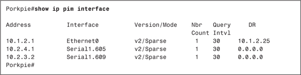
When a host first requests a join to a group, the DR joins the shared RP tree (RPT). Examining Bowler’s unicast routing table in Example 6-16, the route from Bowler to the RP is through Porkpie, via subnet 10.1.2.0/24. You now know why Porkpie’s E0 interface is on the outgoing interface list of the (*, G) entry. This entry represents the RPT linking Bowler to Stetson. Bowler’s (*, G) entry has an empty outgoing interface list and a pruned flag set because it is the endpoint of the RPT branch.
Example 6-16 The Shortest Route to the RP from Bowler Is Across Its Connected Ethernet to Porkpie
Bowler#show ip route 10.224.1.1
Routing entry for 10.224.1.1/32
Known via "ospf 1", distance 110, metric 75, type intra area
Redistributing via ospf 1
Last update from 10.1.2.1 on Ethernet0, 01:03:56 ago
Routing Descriptor Blocks:
* 10.1.2.1, from 10.224.1.1, 01:03:56 ago, via Ethernet0
Route metric is 75, traffic share count is 1
Bowler#
Next, you know that by default after the first multicast packet is received, a PIM-SM router with an attached member will try to switch to the shortest path tree (SPT) to the source, whether that path leads through the RP or not. Bowler’s unicast routing table shows that the shortest route to source subnet 10.1.1.0/24 is through Fedora, as indicated in Example 6-17. Looking again at the mroutes in Example 6-14, Bowler’s (S, G) entry indicates that Fedora, at 10.2.5.2, is the upstream or RPF neighbor. E0 is on the entry’s outgoing interface list and in forward state, because packets are of course being forwarded to the group member. Porkpie is not forwarding packets for this group, so its (S, G) entry has an empty outgoing interface list and a pruned flag.
Example 6-17 Bowler’s Shortest Path to Source Subnet 10.1.1.0/24 Is Through Fedora, Out Interface S1.705
Bowler#show ip route 10.1.1.0
Routing entry for 10.1.1.0/24
Known via "ospf 1", distance 110, metric 138, type intra area
Redistributing via ospf 1
Last update from 10.2.5.2 on Serial1.705, 01:17:30 ago
Routing Descriptor Blocks:
* 10.2.5.2, from 10.1.1.1, 01:17:30 ago, via Serial1.705
Route metric is 138, traffic share count is 1
Bowler#
You also can use debugging to see how the multicast packets are being forwarded. Example 6-18 shows that Bowler is receiving the multicast packets for group 228.13.20.216 from source 10.1.1.88, via Fedora on interface S1.705. The packets are being forwarded out interface E0 to the connected group member.
Example 6-18 Using Debugging to Capture IP Multicast Packets (mpackets), You Can Observe That Bowler Is Receiving Packets for (10.1.1.88, 228.13.20.216) on Interface S1.705 and Forwarding Them Out Interface E0
Bowler#debug ip mpacket 228.13.20.216
IP multicast packets debugging is on for group 228.13.20.216
Bowler#
IP: s=10.1.1.88 (Serial1.705) d=228.13.20.216 (Ethernet0) len 573, mforward
IP: s=10.1.1.88 (Serial1.705) d=228.13.20.216 (Ethernet0) len 573, mforward
IP: s=10.1.1.88 (Serial1.705) d=228.13.20.216 (Ethernet0) len 573, mforward
IP: s=10.1.1.88 (Serial1.705) d=228.13.20.216 (Ethernet0) len 573, mforward
IP: s=10.1.1.88 (Serial1.705) d=228.13.20.216 (Ethernet0) len 573, mforward
IP: s=10.1.1.88 (Serial1.705) d=228.13.20.216 (Ethernet0) len 573, mforward
IP: s=10.1.1.88 (Serial1.705) d=228.13.20.216 (Ethernet0) len 573, mforward
IP: s=10.1.1.88 (Serial1.705) d=228.13.20.216 (Ethernet0) len 573, mforward
IP: s=10.1.1.88 (Serial1.705) d=228.13.20.216 (Ethernet0) len 573, mforward
Using the same debugging command at Porkpie also presents interesting results, as demonstrated in Example 6-19. The debug messages show that the router is not receiving packets for group 228.13.20.216 from either the RP or Fedora. Rather, it is receiving the packets that Bowler is forwarding onto the Ethernet subnet 10.1.2.0/24. Porkpie’s mroute entries in Example 6-14 show the RPF interface for the group to be S1.609. Because the packets are being received on E0, the RPF check fails, and the packets are dropped.
Example 6-19 Porkpie Is Not Forwarding Any Packets for Group 228.13.20.216
Porkpie#debug ip mpacket 228.13.20.216
IP multicast packets debugging is on for group 228.13.20.216
Porkpie#
IP: s=10.1.1.88 (Ethernet0) d=228.13.20.216 len 583, not RPF interface
IP: s=10.1.1.88 (Ethernet0) d=228.13.20.216 len 583, not RPF interface
IP: s=10.1.1.88 (Ethernet0) d=228.13.20.216 len 583, not RPF interface
IP: s=10.1.1.88 (Ethernet0) d=228.13.20.216 len 583, not RPF interface
IP: s=10.1.1.88 (Ethernet0) d=228.13.20.216 len 583, not RPF interface
IP: s=10.1.1.88 (Ethernet0) d=228.13.20.216 len 583, not RPF interface
IP: s=10.1.1.88 (Ethernet0) d=228.13.20.216 len 583, not RPF interface
IP: s=10.1.1.88 (Ethernet0) d=228.13.20.216 len 583, not RPF interface
IP: s=10.1.1.88 (Ethernet0) d=228.13.20.216 len 583, not RPF interface
So much of this example, as shown so far, depends on the fact that a Cisco router switches to the group’s SPT after receiving the first multicast packet. You learned in Chapter 5 that you can change this default with the ip pim spt-threshold command. A threshold can be specified in kilobits per second, and the router will not switch to the SPT until the arrival rate of the group’s packets exceeds the threshold. Alternatively, you can use the infinity keyword, and the router will never switch to the SPT. It is enlightening to see what happens when ip pim spt-threshold infinity is added to the configuration of Bowler in Figure 6-3.Example 6-20 shows the resulting mroute entries at Porkpie and Bowler after Bowler’s reconfiguration. Bowler’s RPT passes out its E0 interface, across subnet 10.1.2.0/24, and through Porkpie. So Porkpie must now forward packets from the RP. But Bowler’s E0 interface also is its RPF interface for the group, and a PIM router cannot forward a group’s packets out that group’s RPF interface. This is simply a multicast version of the split-horizon rule, which states that packets are not forwarded out the interface they arrived on. As a result, Bowler’s (*, G) now sports a pruned flag. Porkpie is now forwarding the packets to the group member. Interestingly, even though Porkpie has assumed the forwarding duties because Bowler must use the RPT, Porkpie itself is under no such constraints and has switched to an SPT through Fedora rather than through the RP.
Example 6-20 After Bowler Is Configured to Never Switch to the SPT, the Forwarding Duties for Group 228.13.20.216 Pass to Porkpie
Porkpie#show ip mroute 228.13.20.216
IP Multicast Routing Table
Flags: D - Dense, S - Sparse, C - Connected, L - Local, P - Pruned
R - RP-bit set, F - Register flag, T - SPT-bit set, J - Join SPT
M - MSDP created entry, X - Proxy Join Timer Running
A - Advertised via MSDP
Outgoing interface flags: H - Hardware switched
Timers: Uptime/Expires
Interface state: Interface, Next-Hop or VCD, State/Mode
(*, 228.13.20.216), 00:45:09/00:02:59, RP 10.224.1.1, flags: SJC
Incoming interface: Serial1.609, RPF nbr 10.2.3.1
Outgoing interface list:
Ethernet0, Forward/Sparse, 00:44:11/00:02:54
(10.1.1.88, 228.13.20.216), 00:44:30/00:02:59, flags: CT
Incoming interface: Serial1.605, RPF nbr 10.2.4.2
Outgoing interface list:
Ethernet0, Forward/Sparse, 00:44:11/00:02:24
Porkpie#
_______________________________________________________________________
Bowler#show ip mroute 228.13.20.216
IP Multicast Routing Table
Flags: D - Dense, S - Sparse, C - Connected, L - Local, P - Pruned
R - RP-bit set, F - Register flag, T - SPT-bit set, J - Join SPT
M - MSDP created entry, X - Proxy Join Timer Running
A - Advertised via MSDP
Outgoing interface flags: H - Hardware switched
Timers: Uptime/Expires
Interface state: Interface, Next-Hop or VCD, State/Mode
(*, 228.13.20.216), 00:45:31/00:02:07, RP 10.224.1.1, flags: SPC
Incoming interface: Ethernet0, RPF nbr 10.1.2.1
Outgoing interface list: Null
Bowler#
At times, you may need to assign different groups to different RPs. Typically this is done as the number of groups in the multicast domain grows, and you need to divide the RP duties to decrease the memory and CPU demands placed on any one router. Figure 6-4 shows the same internetwork you have been observing throughout this section, but now Fedora has also been designated as an RP, with an address of 10.244.1.2. With access lists, you can configure multiple RPs and specify what groups should use what RP.
Figure 6-4 Both Stetson and Fedora Are Rendezvous Points; Access Lists Are Used in Conjunction with the Static RP Addresses to Tell Each Router in the Domain Which RP to Use for a Particular Group
For example, consider the configuration in Example 6-21.
Example 6-21 Bowler’s RP Filtering Configuration
ip pim rp-address 10.224.1.1 10
ip pim rp-address 10.224.1.2 5
!
access-list 5 permit 239.0.0.0 0.255.255.255
access-list 5 permit 228.13.20.0 0.0.0.255
access-list 10 permit 224.2.127.254
access-list 10 permit 230.253.0.0 0.0.255.255
Access list 5 specifies the groups that are permitted to use RP 10.224.1.2 (Fedora), and access list 10 specifies the groups that are allowed to use RP 10.224.1.1 (Stetson). Any group whose address does not match one of these two access lists will not have an RP assigned, and therefore cannot join either shared tree. This configuration is added to Bowler, and Example 6-22 shows the results. A quick examination shows that the groups listed (which are active groups on the router) have been mapped to an RP according to the constraints of access lists 5 and 10.
Example 6-22 The show ip pim rp Command Displays the Groups Active on a Router and the RP to Which They Are Mapped
Bowler#show ip pim rp
Group: 239.255.255.254, RP: 10.224.1.2, v2, uptime 01:20:13, expires 00:02:08
Group: 228.13.20.216, RP: 10.224.1.2, v2, uptime 01:19:30, expires never
Group: 224.2.127.254, RP: 10.224.1.1, v2, uptime 01:20:05, expires never
Group: 230.253.84.168, RP: 10.224.1.1, v2, uptime 01:20:06, expires 00:01:48
Bowler#
Case Study: Configuring Auto-RP
In a stable PIM domain, static configuration of the RP is straightforward. As new routers are added, they are configured with the location of the RP or RPs. Static RP configuration becomes a problem under two circumstances:
• The address of the RP must be changed, either on the existing RP or because a new RP is being installed. The network administrator must change the static configurations on all PIM routers, which in a large domain can involve significant downtime.
• The RP fails. A statically configured PIM domain cannot easily handle a failover to an alternate RP.
Therefore, in all but the smallest PIM domains, the use of one of the two automatic RP discovery mechanisms, Auto-RP or bootstrap, is recommended for both ease of management and better redundancy. This case study demonstrates Auto-RP, and a following case study demonstrates the bootstrap protocol.
As discussed in Chapter 5, Auto-RP is a Cisco-proprietary protocol developed before the bootstrap protocol was proposed as part of PIMv2. Auto-RP must be used with any Cisco IOS Software Release prior to Release 11.3, in which PIMv2 is first supported.
Two steps are required to configure basic Auto-RP:
1. All candidate-RPs must be configured.
2. All mapping agents must be configured.
Candidate RPs (C-RPs) are configured by the ip pim send-rp-announce command. When you enter this command, you specify the interface from which the router takes its RP address, and a TTL value that is added to the advertisement messages. The TTL provides scoping so that packets do not travel outside the boundaries of the domain. When a router is configured as a candidate RP, it begins sending RP-Announce messages to the reserved address 224.0.1.39 every 60 seconds.
The mapping agent listens for RP-Announce messages from the C-RPs and selects the RPs. It then advertises the RPs to the rest of the PIM domain in RP-Discovery messages, sent to the reserved address 224.0.1.40 every 60 seconds.
Figure 6-5 shows a sample topology. Here, routers Stetson and Fedora are candidate RPs with addresses 10.224.1.1 and 10.224.1.2, respectively. Porkpie is the mapping agent, with an identifying address of 10.224.1.3.
Figure 6-5 Stetson and Fedora Are Candidate RPs, and Porkpie Is the Mapping Agent
Example 6-23 shows the relevant parts of Fedora’s configuration.
Example 6-23 Configuring Fedora as a Candidate RP
interface Loopback0
ip address 10.224.1.2 255.255.255.255
!
ip pim send-rp-announce Loopback0 scope 5
Stetson’s configuration is similar. The RP address is taken from interface L0, and the scope keyword sets the TTL of the originated RP-Announce messages.
Example 6-24 shows the configuration establishing Porkpie as a mapping agent.
Example 6-24 Establishing Porkpie as a Mapping Agent
interface Loopback0
ip address 10.224.1.3 255.255.255.255
ip pim sparse-mode
!
ip pim send-rp-discovery Loopback0 scope 5
Again, L0 is used to derive the mapping agent address, and the TTL is set to 5. In the configuration in Example 6-24, notice that PIM-SM must be configured on the loopback interface. This must be performed on the mapping agents; if you fail to enable PIM-SM on the interface first, you will get an error message like the one in Example 6-25.
Example 6-25 Failing to Enable PIM-SM on a Mapping Agent’s Loopback Interface Results in an Error Message
Porkpie(config)#ip pim send-rp-discovery Loopback0 scope 5
Non PIM interface ignored in accepted command.
Porkpie(config)#
The resulting configuration statement will look like the following:
ip pim send-rp-discovery scope 5
The interface specified was not accepted, and as a result, the mapping agent does not work. Unlike mapping agents, PIM does not have to be configured on the loopback interface of a C-RP. Of course, on both mapping agents and C-RPs, PIM-SM must still be configured on all physical interfaces connected to PIM neighbors.
When a Cisco router is first configured with PIM-SM, it begins listening for the address 224.0.1.40. If changes have to be made to either the C-RPs or the mapping agents, the changes are automatically advertised by the changed device, and the routers throughout the domain learn of the change. Perhaps the most important feature, however, is that you can configure multiple RPs for any or all groups. The mapping agent chooses the RP for a group based on the highest RP address. If that RP fails, the mapping agent selects the next-highest qualifying RP and advertises that.
Example 6-26 shows an example of an RP failover. Here, debug ip pim auto-rp is used to display all Auto-RP activity. You can see that Porkpie, the mapping agent in Figure 6-5, is receiving RP-Announce messages from both Stetson (10.224.1.1) and Fedora (10.224.1.2). Because Fedora has the higher IP address, it is being advertised to the domain as the RP for all multicast groups (224.0.0.0/4). After the first reception of RP-Announce messages from Fedora, that router fails. When Porkpie has not heard another RP-Announce message from Fedora within 180 seconds (3 times the announcement interval), it declares the RP dead, selects Stetson as the new RP, and begins advertising the new RP. That sequence of events is highlighted at the bottom of the Debug messages.
Example 6-26 Debugging Is Used to Observe an RP Failover at the Mapping Agent in Figure 6-5
Porkpie#debug ip pim auto-rp
PIM Auto-RP debugging is on
Porkpie#
Auto-RP: Received RP-announce, from 10.224.1.1, RP_cnt 1, ht 181
Auto-RP: Update (224.0.0.0/4, RP:10.224.1.1), PIMv2 v1
Auto-RP: Received RP-announce, from 10.224.1.1, RP_cnt 1, ht 181
Auto-RP: Update (224.0.0.0/4, RP:10.224.1.1), PIMv2 v1
Auto-RP: Received RP-announce, from 10.224.1.2, RP_cnt 1, ht 181
Auto-RP: Update (224.0.0.0/4, RP:10.224.1.2), PIMv2 v1
Auto-RP: Received RP-announce, from 10.224.1.2, RP_cnt 1, ht 181
Auto-RP: Update (224.0.0.0/4, RP:10.224.1.2), PIMv2 v1
Auto-RP: Build RP-Discovery packet
Auto-RP: Build mapping (224.0.0.0/4, RP:10.224.1.2), PIMv2 v1,
Auto-RP: Send RP-discovery packet on Loopback0 (1 RP entries)
Auto-RP: Send RP-discovery packet on Serial1.605 (1 RP entries)
Auto-RP: Send RP-discovery packet on Serial1.609 (1 RP entries)
Auto-RP: Send RP-discovery packet on Ethernet0 (1 RP entries)
Auto-RP: Received RP-announce, from 10.224.1.1, RP_cnt 1, ht 181
Auto-RP: Update (224.0.0.0/4, RP:10.224.1.1), PIMv2 v1
Auto-RP: Received RP-announce, from 10.224.1.1, RP_cnt 1, ht 181
Auto-RP: Update (224.0.0.0/4, RP:10.224.1.1), PIMv2 v1
Auto-RP: Build RP-Discovery packet
Auto-RP: Build mapping (224.0.0.0/4, RP:10.224.1.2), PIMv2 v1,
Auto-RP: Send RP-discovery packet on Loopback0 (1 RP entries)
Auto-RP: Send RP-discovery packet on Serial1.609 (1 RP entries)
Auto-RP: Send RP-discovery packet on Ethernet0 (1 RP entries)
Auto-RP: Received RP-announce, from 10.224.1.1, RP_cnt 1, ht 181
Auto-RP: Update (224.0.0.0/4, RP:10.224.1.1), PIMv2 v1
Auto-RP: Received RP-announce, from 10.224.1.1, RP_cnt 1, ht 181
Auto-RP: Update (224.0.0.0/4, RP:10.224.1.1), PIMv2 v1
Auto-RP: Mapping (224.0.0.0/4, RP:10.224.1.2) expired,
Auto-RP: Build RP-Discovery packet
Auto-RP: Build mapping (224.0.0.0/4, RP:10.224.1.1), PIMv2 v1,
Auto-RP: Send RP-discovery packet on Loopback0 (1 RP entries)
Auto-RP: Send RP-discovery packet on Serial1.609 (1 RP entries)
Auto-RP: Send RP-discovery packet on Ethernet0 (1 RP entries)
Porkpie#
In Example 6-27, the show ip pim rp command is used at Bowler to display the groups that router is receiving for, and the RP that the group is mapped to. The first display is taken before Fedora fails, and shows that all groups are mapped to its RP address. The second display, taken after Fedora fails and the mapping agent advertises the new RP, shows that all groups are now mapped to Stetson.
Example 6-27 Before Fedora Fails, All of Bowler’s Groups Are Mapped to That RP (10.224.1.2); After the Failure, Bowler’s Groups Are Remapped, Based on Information from the Mapping Agent, to Stetson (10.224.1.1)
Bowler#show ip pim rp
Group: 239.255.255.254, RP: 10.224.1.2, v2, v1, uptime 00:08:07, expires 00:04:26
Group: 228.13.20.216, RP: 10.224.1.2, v2, v1, uptime 00:08:08, expires 00:04:26
Group: 224.2.127.254, RP: 10.224.1.2, v2, v1, uptime 00:08:07, expires 00:04:26
Group: 230.253.84.168, RP: 10.224.1.2, v2, v1, uptime 00:08:07, expires 00:04:26
Bowler#
Bowler#show ip pim rp
Group: 239.255.255.254, RP: 10.224.1.1, v2, v1, uptime 00:03:46, expires 00:02:56
Group: 228.13.20.216, RP: 10.224.1.1, v2, v1, uptime 00:03:46, expires 00:02:56
Group: 224.2.127.254, RP: 10.224.1.1, v2, v1, uptime 00:03:46, expires 00:02:56
Group: 230.253.84.168, RP: 10.224.1.1, v2, v1, uptime 00:03:46, expires 00:02:56
Bowler#
To change the 60-second default interval at which a C-RP sends RP-Announce messages, add the interval keyword to the ip pim send-rp-announce command. For example, the following causes Fedora to send RP-Announce messages every 10 seconds:
ip pim send-rp-announce Loopback0 scope 5 interval 10
The holdtime, the interval a mapping agent waits to hear an RP-Announce message from a C-RP, is always 3 times the announcement interval. So the result of the preceding command is to shorten the failover time of Fedora to 30 seconds, at the cost of 6 times as many RP-Announce messages originated by the router.
A C-RP advertises, in its RP-Announce messages, the groups for which it can act as the RP. The default is to announce 224.0.0.0/4, which represents all multicast groups. As with static RPs in the preceding case study, however, you will sometimes want to map different groups to different RPs. Suppose, for example, you want all groups 224.0.0.0 through 231.255.255.255 (224.0.0.0/5) to be mapped to Stetson, and all groups 232.0.0.0 through 239.255.255.255 (232.0.0.0/5) to be mapped to Fedora. The C-RP configurations of those two routers then look like Example 6-28.
Example 6-28 Configuring Stetson and Fedora as C-RPs
Stetsonip pim send-rp-announce Loopback0 scope 5 group-list 20
!
access-list 20 permit 224.0.0.0 7.255.255.255
______________________________________________________________________
Fedoraip pim send-rp-announce Loopback0 scope 5 group-list 30
!
access-list 30 permit 232.0.0.0 7.255.255.255
The group-list keyword ties the ip pim send-rp-announce statement to an access list. The access list then describes the groups for which router can become the RP. Example 6-29 shows the results at Bowler, after mapping agent Porkpie has advertised the RPs according to the constraints in their RP-Announce messages. 239.255.255.254 is mapped to Fedora, while the other three groups, all of whose addresses fall within the 224.0.0.0/5 range, are mapped to Stetson.
Example 6-29 Bowler’s Group-to-RP Mappings, Showing the Constraints Configured at Stetson and Fedora
Bowler#show ip pim rp
Group: 239.255.255.254, RP: 10.224.1.2, v2, v1, uptime 00:04:25, expires 00:02:56
Group: 228.13.20.216, RP: 10.224.1.1, v2, v1, uptime 00:11:05, expires 00:03:57
Group: 224.2.127.254, RP: 10.224.1.1, v2, v1, uptime 00:11:05, expires 00:03:57
Group: 230.253.84.168, RP: 10.224.1.1, v2, v1, uptime 00:11:05, expires 00:03:57
Bowler#
Suppose you also want groups 228.13.0.0 through 228.13.255.255 to be mapped to Fedora. The configuration for router Fedora would then look like Example 6-30.
Example 6-30 Configuring Fedora as the C-RP for Groups 228.13.0.0 through 228.13.255.255
ip pim send-rp-announce Loopback0 scope 5 group-list 30
!
access-list 30 permit 232.0.0.0 7.255.255.255
access-list 30 permit 228.13.0.0 0.0.255.255
Example 6-31 shows the result at Bowler. Note that Stetson’s configuration has not changed. That C-RP is announcing 224.0.0.0/5 as its permitted group range, which includes 228.13.0.0/16. The mapping agent now has two C-RPs for groups in the 228.13.0.0/16 range and has chosen Fedora because its IP address is higher.
Example 6-31 Multicast Group 228.13.20.216, Which Was Mapped to RP 10.224.1.1 in Example 6-29, Is Now Mapped to RP 10.224.1.2
Bowler#show ip pim rp
Group: 239.255.255.254, RP: 10.224.1.2, v2, v1, uptime 00:01:43, expires 00:04:16
Group: 228.13.20.216, RP: 10.224.1.2, v2, v1, uptime 00:01:43, expires 00:04:16
Group: 224.2.127.254, RP: 10.224.1.1, v2, v1, uptime 00:36:05, expires 00:02:47
Group: 230.253.84.168, RP: 10.224.1.1, v2, v1, uptime 00:36:05, expires 00:02:47
Bowler#
Several variants of the show ip pim rp command enable you to observe group-to-RP mappings. The command in its basic form, as used in the previous few examples, shows you only the active groups on a router and the RP to which each group address is matched. To observe the full range of groups that may be matched to an RP, use show ip pim rp mapping, as demonstrated in Example 6-32.
Example 6-32 Through the Reception of RP-Discovery Messages from the Mapping Agent 10.224.1.3, Bowler Has Mapped Three Ranges of Multicast Group Addresses to Two Different RPs
Bowler#show ip pim rp mapping
PIM Group-to-RP Mappings
Group(s) 224.0.0.0/5
RP 10.224.1.1 (?), v2v1
Info source: 10.224.1.3 (?), via Auto-RP
Uptime: 01:14:37, expires: 00:02:42
Group(s) 228.13.0.0/16
RP 10.224.1.2 (?), v2v1
Info source: 10.224.1.3 (?), via Auto-RP
Uptime: 00:43:15, expires: 00:02:37
Group(s) 232.0.0.0/5
RP 10.224.1.2 (?), v2v1
Info source: 10.224.1.3 (?), via Auto-RP
Uptime: 00:43:15, expires: 00:02:41
Bowler#
A similar command is show ip pim rp mapping in-use, as demonstrated in Example 6-33. In addition to the information displayed in Example 6-32, the group ranges that are currently in use on the router are displayed. Notice that the output in both Example 6-32 and 6-33 displays the source of the mapping agent, 10.224.1.3. This information proves useful when there are multiple mapping agents.
Example 6-33 The in-use Keyword Displays the Group Address Ranges That Are Currently in Use on the Router
Bowler#show ip pim rp mapping in-use
PIM Group-to-RP Mappings
Group(s) 224.0.0.0/5
RP 10.224.1.1 (?), v2v1
Info source: 10.224.1.3 (?), via Auto-RP
Uptime: 01:21:24, expires: 00:02:50
Group(s) 228.13.0.0/16
RP 10.224.1.2 (?), v2v1
Info source: 10.224.1.3 (?), via Auto-RP
Uptime: 00:50:02, expires: 00:02:49
Group(s) 232.0.0.0/5
RP 10.224.1.2 (?), v2v1
Info source: 10.224.1.3 (?), via Auto-RP
Uptime: 00:50:02, expires: 00:02:48
RPs in Auto-RP cache that are in use:
Group(s): 224.0.0.0/5, RP: 10.224.1.1
Group(s): 232.0.0.0/5, RP: 10.224.1.2
Group(s): 228.13.0.0/16, RP: 10.224.1.2
Bowler#
On occasion, you may want to know what RP a particular group address will be mapped to, before that address is active on a router. Suppose, for example, you want to know what RP the group 235.1.2.3 will be mapped to at Bowler. For this, you use the show ip pim rp-hash command, as demonstrated in Example 6-34. The result shows that group 235.1.2.3 will be mapped to RP 10.224.1.2. The result is consistent with the access list constraints configured previously.
Example 6-34 The Command show ip pim rp-hash Enables You to Determine to Which RP a Particular Group Will Be Mapped
Bowler#show ip pim rp-hash 235.1.2.3
RP 10.224.1.2 (?), v2v1
Info source: 10.224.1.3 (?), via Auto-RP
Uptime: 00:55:48, expires: 00:02:00
Bowler#
You can prevent your mapping agents from accepting unauthorized routers that may have been inadvertently or intentionally configured as C-RPs by setting up an RP announcement filter. Example 6-35 demonstrates a sample configuration for Porkpie.
Example 6-35 Configuring Porkpie with an RP Announcement Filter
ip pim rp-announce-filter rp-list 1 group-list 11
ip pim send-rp-discovery Loopback0 scope 5
!
access-list 1 permit 10.224.1.2
access-list 1 permit 10.224.1.1
access-list 11 permit 224.0.0.0 15.255.255.255
The configuration in Example 6-35 establishes an RP announcement filter to accept only the C-RPs specified in access list 1, and to accept groups advertised by those C-RPs only if they are specified in access list 11. In this configuration, access list 1 permits Stetson and Fedora and permits those routers to be C-RPs for all multicast groups.
Throughout this case study, Stetson and Fedora in Figure 6-5 have been the C-RPs and Porkpie has been the mapping agent for the sake of clarity. In practice, however, it makes little sense to configure multiple C-RPs for redundancy but configure only a single mapping agent. If the mapping agent fails, no RPs are advertised to the domain, and PIM-SM fails. A more real-life approach would be to make Stetson and Fedora both C-RPs and mapping agents. The nature of Auto-RP ensures that both mapping agents will derive and advertise the same RPs, and if one router fails, the other is still in service to advertise RPs to the domain.
Case Study: Configuring Sparse-Dense Mode
A slight "cheat" was used in the examples of the preceding case study. Examining Figure 6-5, notice that the C-RPs are directly connected to the mapping agent, and the mapping agent is directly connected to Bowler. In Figure 6-6, Homburg is now configured as the Auto-RP mapping agent. This topology gives rise to an interesting dilemma: Homburg advertises the RPs to all routers in RP-Discovery messages, using the reserve address 224.0.1.40. All PIM-SM routers listen for this address. In a sparse-mode environment, however, multicast packets must initially be forwarded on shared trees. That means the routers listening for 224.0.1.40 must notify their RP that they want to join that group, in order to receive the RP-Discovery messages. But how do the routers know where the RP is if they have not yet received the RP-Discovery messages?
Figure 6-6 Homburg Is Now the Mapping Agent
The same Catch-22 would apply to the C-RPs if they were not directly connected to the mapping agent. The mapping agent must receive RP-Announce messages from the C-RPs in order to select an RP, and to do this, it must join group 224.0.1.39. It cannot join this group, however, if it does not know where the RPs are, and it cannot know where the RPs are unless it receives RP-Announce messages.
PIM sparse-dense mode was created to overcome this problem. When an interface is configured in this mode, it uses sparse mode if an RP is known for the group. If no RP is known, it uses dense mode. In the case of 224.0.1.39 and 224.0.1.40, the groups are assumed to be in dense mode. Example 6-36 shows the sparse-dense mode configuration for Homburg.
Example 6-36 PIM Sparse-Dense Mode Configuration for Router Homburg
hostname Homburg
!
ip multicast-routing
!
interface Loopback0
ip address 10.224.1.4 255.255.255.0
ip pim sparse-mode
!
interface Ethernet0/0
ip address 10.1.1.1 255.255.255.0
ip pim sparse-dense-mode
no ip mroute-cache
!
interface Serial0/1
no ip address
encapsulation frame-relay
no ip mroute-cache
!
interface Serial0/1.305 point-to-point
description PVC to R5
ip address 10.2.1.1 255.255.255.0
ip pim sparse-dense-mode
no ip mroute-cache
frame-relay interface-dlci 305
!
interface Serial0/1.309 point-to-point
description PVC to R9
ip address 10.2.2.1 255.255.255.0
ip pim sparse-dense-mode
no ip mroute-cache
frame-relay interface-dlci 309
!
router ospf 1
network 10.0.0.0 0.255.255.255 area 0
!
ip pim send-rp-discovery Loopback0 scope 5
!
The command ip pim sparse-dense-mode is used on all the physical interfaces, and it is configured similarly on all physical interfaces of all routers in the topology of Figure 6-6. The loopback interface is only in sparse mode, because it is needed only as the mapping agent address and never must make any sparse/dense determinations. Interface E0/0 could also be put into sparse mode, because it does not face any downstream routers and would not have to make sparse/dense decisions. However, it is good practice to place all interfaces in sparse-dense mode for consistency. In fact, it is commonly advised to use this mode in all modern PIM domains as long as all routers support the mode.
Example 6-37 shows the multicast routing table on Homburg after the reconfiguration. Notice that the entries for (*, 224.0.1.39) and (*, 224.0.1.40) have D flags, indicating that they are operating in dense mode. All other (*, G) entries are flagged as sparse.
Example 6-37 The Flags Associated with (*,224.0.1.39) and (*,224.0.1.40) in Homburg’s mroute Table Show That Those Groups Are Operating in Dense Mode
Homburg#show ip mroute
IP Multicast Routing Table
Flags: D - Dense, S - Sparse, C - Connected, L - Local, P - Pruned
R - RP-bit set, F - Register flag, T - SPT-bit set, J - Join SPT
Timers: Uptime/Expires
Interface state: Interface, Next-Hop, State/Mode
(*, 228.13.20.216), 00:20:42/00:02:59, RP 10.224.1.2, flags: SJCF
Incoming interface: Serial0/1.305, RPF nbr 10.2.1.2
Outgoing interface list:
Ethernet0/0, Forward/Sparse-Dense, 00:20:42/00:02:43
(10.1.1.88/32, 228.13.20.216), 00:20:42/00:02:59, flags: CFT
Incoming interface: Ethernet0/0, RPF nbr 0.0.0.0
Outgoing interface list:
Serial0/1.305, Forward/Sparse-Dense, 00:20:04/00:02:47
(*, 224.2.127.254), 00:20:34/00:02:59, RP 10.224.1.2, flags: SJCF
Incoming interface: Serial0/1.305, RPF nbr 10.2.1.2
Outgoing interface list:
Ethernet0/0, Forward/Sparse-Dense, 00:20:34/00:02:42
(10.1.1.88/32, 224.2.127.254), 00:20:34/00:02:56, flags: CFT
Incoming interface: Ethernet0/0, RPF nbr 0.0.0.0
Outgoing interface list:
Serial0/1.305, Forward/Sparse-Dense, 00:20:06/00:02:44
(*, 224.0.1.39), 00:20:32/00:00:00, RP 0.0.0.0, flags: DJCL
Incoming interface: Null, RPF nbr 0.0.0.0
Outgoing interface list:
Ethernet0/0, Forward/Sparse-Dense, 00:20:32/00:00:00
Serial0/1.305, Forward/Sparse-Dense, 00:20:32/00:00:00
Serial0/1.309, Forward/Sparse-Dense, 00:20:32/00:00:00
(10.224.1.1/32, 224.0.1.39), 00:20:32/00:02:27, flags: CLT
Incoming interface: Serial0/1.309, RPF nbr 10.2.2.2
Outgoing interface list:
Ethernet0/0, Forward/Sparse-Dense, 00:20:32/00:00:00
Serial0/1.305, Forward/Sparse-Dense, 00:20:32/00:00:00
(10.224.1.2/32, 224.0.1.39), 00:19:54/00:02:05, flags: CLT
Incoming interface: Serial0/1.305, RPF nbr 10.2.1.2
Outgoing interface list:
Ethernet0/0, Forward/Sparse-Dense, 00:19:54/00:00:00
Serial0/1.309, Forward/Sparse-Dense, 00:19:54/00:02:08
(*, 224.0.1.40), 00:20:13/00:00:00, RP 0.0.0.0, flags: DJCL
Incoming interface: Null, RPF nbr 0.0.0.0
Outgoing interface list:
Ethernet0/0, Forward/Sparse-Dense, 00:20:14/00:00:00
Serial0/1.305, Forward/Sparse-Dense, 00:20:14/00:00:00
Serial0/1.309, Forward/Sparse-Dense, 00:20:14/00:00:00
(10.224.1.4/32, 224.0.1.40), 00:20:06/00:02:48, flags: CLT
Incoming interface: Loopback0, RPF nbr 0.0.0.0
Outgoing interface list:
Ethernet0/0, Forward/Sparse-Dense, 00:20:06/00:00:00
Serial0/1.305, Forward/Sparse-Dense, 00:20:06/00:00:00
Serial0/1.309, Forward/Sparse-Dense, 00:20:06/00:00:00
Homburg#
Besides the two Auto-RP groups, sometimes you might want to have some groups operating in sparse mode and others operating in dense mode. By using the ip pim send-rp-announce group-list command at the C-RPs, as demonstrated in the preceding case study, you can regulate what groups are mapped to the RP, and hence operate in sparse mode. Any groups not mapped to an RP will operate in dense mode.
Case Study: Configuring the Bootstrap Protocol
When PIMv2 was first described in RFC 2117, the bootstrap protocol was specified as the mechanism for automatic RP discovery. Cisco first supported PIMv2 in Cisco IOS Software Release 11.3T, and the bootstrap protocol is included in that support.
The two steps to configure bootstrap are very similar to the two steps for configuring Auto-RP:
1. All candidate RPs must be configured.
2. All candidate bootstrap routers (C-BSRs) must be configured.
Figure 6-7 shows the same PIM topology used in the preceding two case studies, but now it is running bootstrap rather than Auto-RP. Stetson and Fedora are again the C-RPs, but now they are also C-BSRs in keeping with a more robust design, providing failover for both the RP and BSR function.
Figure 6-7 Stetson and Fedora Serve as Both Candidate RPs and Candidate BSRs
Example 6-38 shows the relevant configurations of Stetson and Fedora.
Example 6-38 Configuring Routers Stetson and Fedora as Both Candidate RPs and Candidate BSRs
Stetson
interface Loopback0
 ip address 10.224.1.1 255.255.255.255
!
ip pim bsr-candidate Loopback0 0
ip pim rp-candidate Loopback0
_______________________________________________________________________
Fedora
interface Loopback0
 ip address 10.224.1.2 255.255.255.255
!
ip pim bsr-candidate Loopback0 0
ip pim rp-candidate Loopback0
The command ip pim bsr-candidate sets the router as a C-BSR and specifies that the BSR address is to be taken from interface L0. The 0 at the end of the command specifies the hash-mask length, which is 0 by default on Cisco routers. Use of the hash-mask is demonstrated later in this case study. The command ip pim rp-candidate sets the router as a C-RP and specifies that the RP address also is to be taken from interface L0.
First, a BSR must be elected from the available C-BSRs. The C-BSRs send Bootstrap messages throughout the PIM domain, with the destination address 224.0.0.13, that contain the originator’s BSR address and priority. In the configuration so far, the default priority of 0 and the default hash-mask length of 0 remain unchanged, and therefore equal, on both C-BSRs. As a result, the higher BSR address is used as a tiebreaker. Fedora’s BSR address (10.224.1.2) is higher than Stetson’s (10.224.1.1), so Fedora is the BSR. Example 6-39 confirms the fact. By using show ip pim bsr-router on any router in the domain, you can observe not only the active BSR, but also the BSR’s address, uptime, priority, hash-mask length, and holdtime.
Example 6-39 The show ip pim bsr-router Command Displays the PIMv2 Domain’s BSR
Bowler#show ip pim bsr-router
PIMv2 Bootstrap information
BSR address: 10.224.1.2 (?)
Uptime: 00:17:35, BSR Priority: 0, Hash mask length: 0
Expires: 00:01:56
Bowler#
When the C-RPs receive the Bootstrap messages and determine the address of the BSR, they unicast their Candidate-RP-Advertisement messages to the BSR. These messages contain the C-RP’s address and priority. The BSR collects the C-RPs into an RP-Set, which is then included in its Bootstrap messages. This is where bootstrap diverges sharply from Auto-RP: Unlike the Auto-RP mapping agent, the BSR does not select RPs. The PIMv2 routers receive the Bootstrap messages, and they select the RP. The algorithm used to make the selection ensures that all routers select the same RPs for the same groups.
Example 6-40 shows the group-to-RP mappings at Bowler. You can see that the RP is Stetson, which is elected RP because of its lower RP address. (The C-RP priorities in this example are equal.)
Example 6-40 The Active Groups at Bowler Are All Mapped to Stetson. Unlike Auto-RP, the C-RP with the Lowest RP Address Is Elected as the RP
Bowler#show ip pim rp
Group: 239.255.255.254, RP: 10.224.1.1, v2, uptime 00:25:16, expires 00:02:40
Group: 228.13.20.216, RP: 10.224.1.1, v2, uptime 00:25:16, expires 00:02:40
Group: 224.2.127.254, RP: 10.224.1.1, v2, uptime 00:25:16, expires 00:02:40
Group: 230.253.84.168, RP: 10.224.1.1, v2, uptime 00:25:16, expires 00:02:40
Bowler#
Example 6-41 shows the complete group address range that is mapped to the RP. Compare this display to that of Example 6-33; of particular interest here is that the mapping is shown to be derived from bootstrap, and that the router knows all the C-RPs from the RP-Set.
Example 6-41 Bowler Indicates That It Is Aware of Both Stetson and Fedora as C-RPs
Bowler#show ip pim rp mapping
PIM Group-to-RP Mappings
Group(s) 224.0.0.0/4
RP 10.224.1.1 (?), v2
Info source: 10.224.1.2 (?), via bootstrap
Uptime: 00:29:07, expires: 00:02:30
RP 10.224.1.2 (?), v2
Info source: 10.224.1.2 (?), via bootstrap
Uptime: 00:29:07, expires: 00:02:17
Bowler#
The default behavior of both the BSR and the RP can be changed. In Example 6-39, for instance, the BSR is Fedora because its IP address is higher. If you want Stetson to be the BSR, with Fedora acting only as a backup in case Stetson fails, you can change Stetson’s priority to something higher than the default of 0. To change Stetson’s priority to 100, you need to configure Stetson as in Example 6-42.
Example 6-42 Configuring Stetson with a Priority of 100 to Make It the BSR
interface Loopback0
ip address 10.224.1.1 255.255.255.255
!
ip pim bsr-candidate Loopback0 0 100
ip pim rp-candidate Loopback0
Example 6-43 shows the results of the new configuration. Bowler now shows Stetson as the BSR, with a priority of 100. Fedora assumes that role only if Stetson fails.
Example 6-43 Stetson (10.224.1.1), with a Priority of 100, Has Become the BSR
Bowler#show ip pim bsr-router
PIMv2 Bootstrap information
BSR address: 10.224.1.1 (?)
Uptime: 00:10:27, BSR Priority: 100, Hash mask length: 0
Expires: 00:02:02
Bowler#
As with Auto-RP, you also can use access lists to distribute the RP duties among multiple RPs. Suppose, for example, that you want Fedora to be the RP for any groups whose addresses are in the 228.13.0.0/16 range, and Stetson to be the RP for all other groups. You use the configurations in Example 6-44.
Example 6-44 Distributing RP Duties Between Fedora and Stetson
Stetsoninterface Loopback0
ip address 10.224.1.1 255.255.255.255
!
ip pim bsr-candidate Loopback0 0 100
ip pim rp-candidate Loopback0 group-list 20
!
access-list 20 deny 228.13.0.0 0.0.255.255
access-list 20 permit any
_______________________________________________________________________
Fedorainterface Loopback0
ip address 10.224.1.2 255.255.255.255
!
ip pim bsr-candidate Loopback0 0
ip pim rp-candidate Loopback0 group-list 10
!
access-list 10 permit 228.13.0.0 0.0.255.255
Example 6-45 shows the results of these configurations. The BSR advertises the constraints in its Bootstrap messages, and Bowler maps its groups to the RPs based on those constraints. Of course, these configurations are not advised in a real internetwork. If one RP fails, the other can no longer assume a backup role. A more practical implementation would use access lists to distribute groups among multiple C-RPs, with at least two C-RPs for each group range created by the access lists.
Example 6-45 After the Access Lists Are Added to Constrain the RP Mappings at Stetson and Fedora, Bowler Has Mapped Group 228.13.20.216 to Fedora and the Other Groups to Stetson
Bowler#show ip pim rp mapping
PIM Group-to-RP Mappings
Group(s) 224.0.0.0/4
RP 10.224.1.1 (?), v2
Info source: 10.224.1.1 (?), via bootstrap
Uptime: 00:07:25, expires: 00:02:26
Group(s) 228.13.0.0/16
RP 10.224.1.2 (?), v2
Info source: 10.224.1.1 (?), via bootstrap
Uptime: 00:07:25, expires: 00:02:54
Bowler#show ip pim rp
Group: 239.255.255.254, RP: 10.224.1.1, v2, uptime 00:07:30, expires 00:02:52
Group: 228.13.20.216, RP: 10.224.1.2, v2, uptime 00:07:30, expires 00:03:32
Group: 224.2.127.254, RP: 10.224.1.1, v2, uptime 00:07:30, expires 00:02:52
Group: 230.253.84.168, RP: 10.224.1.1, v2, uptime 00:07:30, expires 00:02:52
Bowler#
A better way to distribute the RP duties when using PIMv2 bootstrap is to use the hash-mask. The hash-mask is a 32-bit number assigned to the BSR, and it is used in a somewhat similar fashion to a standard IP address mask. The BSR advertises the hash-mask in its Bootstrap messages, and the receiving routers run a hash algorithm that assigns a consecutive number of group addresses to one C-RP and then assigns the next group of addresses to the next C-RP.
If the hash-mask is 30 bits, for example, it masks the first 30 bits of all IP multicast addresses. The last 2 bits describe a range of four group addresses that will be assigned to an RP. So the addresses 225.1.1.0, 225.1.1.1, 225.1.1.2, and 225.1.1.3 are all part of one range and are assigned to one RP. The addresses 225.1.1.4, 225.1.1.5, 225.1.1.6, and 225.1.1.7 belong to the next range and are assigned to another RP. This "bundling" of group addresses continues throughout the entire IP multicast address range and across all available C-RPs. The result is that the IP multicast group addresses have been evenly distributed among the C-RPs. The mask gives you the flexibility to decide how many consecutive addresses are bundled into a single range so that related addresses are more likely to share the same RP. If the mask is 26 bits, for instance, 64 consecutive addresses are assigned to each range.
The hash-mask length is specified as part of the ip pim bsr-candidate command. As you have observed in previous examples in this case study, the default mask length is 0, meaning that there is a single bundle of group addresses spanning the entire range of the IP multicast address space. Example 6-46 shows the configurations to assign a hash-mask length of 30 for both Stetson and Fedora in Figure 6-7.
Example 6-46 Assigning a Hash-Mask Length of 30 to Routers Stetson and Fedora
Stetsoninterface Loopback0
ip address 10.224.1.1 255.255.255.255
!
ip pim bsr-candidate Loopback0 30
ip pim rp-candidate Loopback0
______________________________________________________________________
Fedorainterface Loopback0
ip address 10.224.1.2 255.255.255.255
!
ip pim bsr-candidate Loopback0 30
ip pim rp-candidate Loopback0
In Example 6-47, the show ip pim rp-hash command is used to demonstrate the results. Beginning with 231.1.1.0, you can see that it and the next three consecutive group addresses are mapped to Fedora. Continuing the sequence, the next four addresses are mapped to Stetson. Across the entire range of IP multicast addresses, there should be a 50-50 distribution between the two RPs.
Example 6-47 The Hash Algorithm Distributes Group Addresses Evenly Among the Available C-RPs
Bowler#show ip pim rp-hash 231.1.1.0
RP 10.224.1.2 (?), v2
Info source: 10.224.1.2 (?), via bootstrap
Uptime: 07:22:14, expires: 00:02:29
Bowler#show ip pim rp-hash 231.1.1.1
RP 10.224.1.2 (?), v2
Info source: 10.224.1.2 (?), via bootstrap
Uptime: 07:22:19, expires: 00:02:24
Bowler#show ip pim rp-hash 231.1.1.2
RP 10.224.1.2 (?), v2
Info source: 10.224.1.2 (?), via bootstrap
Uptime: 07:22:22, expires: 00:02:21
Bowler#show ip pim rp-hash 231.1.1.3
RP 10.224.1.2 (?), v2
Info source: 10.224.1.2 (?), via bootstrap
Uptime: 07:22:28, expires: 00:02:15
Bowler#show ip pim rp-hash 231.1.1.4
RP 10.224.1.1 (?), v2
Info source: 10.224.1.2 (?), via bootstrap
Uptime: 07:22:31, expires: 00:02:13
Bowler#show ip pim rp-hash 231.1.1.5
RP 10.224.1.1 (?), v2
Info source: 10.224.1.2 (?), via bootstrap
Uptime: 07:22:35, expires: 00:02:10
Bowler#show ip pim rp-hash 231.1.1.6
RP 10.224.1.1 (?), v2
Info source: 10.224.1.2 (?), via bootstrap
Uptime: 07:22:38, expires: 00:02:06
Bowler#show ip pim rp-hash 231.1.1.7
RP 10.224.1.1 (?), v2
Info source: 10.224.1.2 (?), via bootstrap
Uptime: 07:22:43, expires: 00:02:02
Case Study: Multicast Load Sharing
At times, you may want to balance multicast traffic over parallel equal-cost paths, either to more fully utilize available bandwidth or to prevent a single path from becoming congested by heavy multicast traffic. But the RPF check prevents multicast load balancing directly over physical links.
The problem is illustrated in Figure 6-8, where the same PIM topology used in the previous case studies is repeated, except that Bowler is removed and Homburg is both the Auto-RP mapping agent and the RP.
Figure 6-8 Two Equal-Cost Paths Exist between the Multicast Source and the Group Member
There are two equal-cost paths from the multicast source attached to Homburg and the group member attached to Porkpie: One path transits Fedora; the other transits Stetson. The problem exists because RPF must have only one incoming interface to work correctly. That means that if Fedora is chosen as the RPF neighbor, and group traffic arrives from Stetson, that traffic will not arrive on the RPF interface and will be dropped. Likewise, if Stetson is chosen as the RPF neighbor, traffic arriving from Fedora will fail the RPF check and be dropped. RPF requires all traffic to arrive on the same upstream interface.
The way to get around this problem is to use a tunnel, as shown in Figure 6-9. The tunnel is built between the loopback interfaces of Homburg and Porkpie, and all multicast traffic from the source to the group member is sent to this virtual tunnel interface rather than to either physical link. The multicast packets are then encapsulated and forwarded as regular IP packets. At this point, the encapsulated packets can be balanced across the two links, using either the default per-destination balancing or the optional per-packet balancing, as described in Volume I.
Figure 6-9 To Load Balance Over the Equal-Cost Paths, a Tunnel Is Created Between Homburg and Porkpie
Note
Per-packet load balancing is achieved by turning off fast switching or its equivalent with the command no ip route-cache on the necessary interfaces.
When the packets arrive at Porkpie, it does not matter whether they were received from Fedora or from Stetson, because their destination is the egress of the tunnel. At the virtual tunnel interface, the encapsulation is removed. From the perspective of the PIM process at Porkpie, the multicast packets appear to have all been received on the same interface, TU0, and to have been received from the same upstream neighbor, Homburg.
Example 6-48 shows the configurations of Homburg and Porkpie.
Example 6-48 Configuring a Tunnel Between Homburg and Porkpie to Load Balance Over Equal-Cost Paths
Homburg
hostname Homburg
!
ip multicast-routing
!
interface Loopback0
 ip address 10.224.1.4 255.255.255.0
 ip pim sparse-mode
!
interface Tunnel0
 ip address 10.224.2.1 255.255.255.252
 ip pim sparse-dense-mode
 tunnel source Loopback0
 tunnel destination 10.224.1.3
!
interface Ethernet0/0
 ip address 10.1.1.1 255.255.255.0
 ip pim sparse-dense-mode
!
interface Serial0/1
 no ip address
 encapsulation frame-relay
!
interface Serial0/1.305 point-to-point
 description PVC to R5
 ip address 10.2.1.1 255.255.255.0
 frame-relay interface-dlci 305
!
interface Serial0/1.309 point-to-point
 description PVC to R9
 ip address 10.2.2.1 255.255.255.0
 frame-relay interface-dlci 309
!
router ospf 1
 passive-interface Tunnel0
 network 10.0.0.0 0.255.255.255 area 0
!
ip pim send-rp-announce Loopback0 scope 5
ip pim send-rp-discovery scope 5
_______________________________________________________________________
Porkpiehostname Porkpie
!
ip multicast-routing
!
interface Loopback0
ip address 10.224.1.3 255.255.255.255
!
interface Tunnel0
ip address 10.224.2.2 255.255.255.252
ip pim sparse-dense-mode
tunnel source Loopback0
tunnel destination 10.224.1.4
!
interface Ethernet0
ip address 10.1.2.1 255.255.255.0
ip pim sparse-dense-mode
ip cgmp
!
interface Serial1
no ip address
encapsulation frame-relay
!
interface Serial1.605 point-to-point
description PVC to R5
ip address 10.2.4.1 255.255.255.0
frame-relay interface-dlci 605
!
interface Serial1.609 point-to-point
description PVC to R9
ip address 10.2.3.2 255.255.255.0
frame-relay interface-dlci 609
!
router ospf 1
passive-interface Tunnel0
network 10.0.0.0 0.255.255.255 area 0
On both routers, the tunnel interface is configured with a source of the router’s loopback interface and a destination of the other router’s loopback interface. The tunnel is using generic route encapsulation (GRE) and is given an IP address so that the virtual interface appears to the routing processes to be a physical IP interface. Finally, PIM is enabled on the tunnel interfaces. Notice that PIM is not enabled on any of the subinterfaces connecting to Stetson and Fedora. And on those two routers, multicasting is not enabled at all. Example 6-49 shows that, with these configurations, Porkpie has established a PIM adjacency with Homburg over the tunnel.
Example 6-49 Porkpie Shows Homburg as a Neighbor Across the GRE Tunnel
Porkpie#show ip pim neighbor
PIM Neighbor Table
Neighbor Address Interface Uptime Expires Ver Mode
10.224.2.1 Tunnel0 04:09:21 00:01:11 v1 Sparse-Dense
Porkpie#
There is a further RPF problem to be solved, however. When Porkpie receives packets from source 10.1.1.88, it checks the unicast routing table for the upstream neighbor. Example 6-50 shows what the router finds.
Example 6-50 The Unicast Routing Table Still Shows 10.2.3.1 or 10.2.4.2 as the Next-Hop Addresses to Reach 10.1.1.88
Porkpie#show ip route 10.1.1.88
Routing entry for 10.1.1.0/24
Known via "ospf 1", distance 110, metric 138, type intra area
Redistributing via ospf 1
Last update from 10.2.3.1 on Serial1.609, 01:13:30 ago
Routing Descriptor Blocks:
* 10.2.3.1, from 10.224.1.4, 01:13:30 ago, via Serial1.609
Route metric is 138, traffic share count is 1
10.2.4.2, from 10.224.1.4, 01:13:30 ago, via Serial1.605
Route metric is 138, traffic share count is 1
Porkpie#
Porkpie’s OSPF configuration has interface TU0 in passive mode to ensure that no unicast traffic crosses the tunnel—only multicast. Unfortunately, this means that OSPF still sees either Stetson (10.2.3.1) or Fedora (10.2.4.2) as the next hop toward 10.1.1.88. So when packets from 10.1.1.88 arrive on the tunnel interface, the RPF check fails, as demonstrated in Example 6-51.
Example 6-51 The RPF Check Fails for Packets Arriving Over the Tunnel from 10.1.1.88 Because the Unicast Routing Table Does Not Show TU0 As an Upstream Interface to That Address
Porkpie#debug ip mpacket
IP multicast packets debugging is on
Porkpie#
IP: s=10.1.1.88 (Tunnel0) d=228.13.20.216 len 569, not RPF interface
IP: s=10.1.1.88 (Tunnel0) d=228.13.20.216 len 569, not RPF interface
IP: s=10.1.1.88 (Tunnel0) d=228.13.20.216 len 569, not RPF interface
IP: s=10.1.1.88 (Tunnel0) d=228.13.20.216 len 569, not RPF interface
IP: s=10.1.1.88 (Tunnel0) d=228.13.20.216 len 569, not RPF interface
IP: s=10.1.1.88 (Tunnel0) d=228.13.20.216 len 569, not RPF interface
IP: s=10.1.1.88 (Tunnel0) d=228.13.20.216 len 569, not RPF interface
IP: s=10.1.1.88 (Tunnel0) d=228.13.20.216 len 569, not RPF interface
IP: s=10.1.1.88 (Tunnel0) d=228.13.20.216 len 569, not RPF interface
IP: s=10.1.1.88 (Tunnel0) d=228.13.20.216 len 569, not RPF interface
To overcome this second RPF problem, a static multicast route is used. Static mroutes are similar to static unicast routes in that they override any dynamic route entries. The difference is that static mroutes are not used for any forwarding. Instead, they are used to statically configure the RPF interface for a source, overriding the information in the unicast routing table. The command ip mroute is used along with an IP address and mask to specify an address or range of addresses. An RPF interface or RPF neighbor address also is specified, just as a static unicast route specifies either an outgoing interface or a next-hop neighbor. Example 6-52 shows the configuration for Porkpie with the static mroute.
Example 6-52 Configuring Porkpie with a Static mroute
hostname Porkpie
!
ip multicast-routing
!
interface Loopback0
 ip address 10.224.1.3 255.255.255.255
!
interface Tunnel0
 ip address 10.224.2.2 255.255.255.252
 ip pim sparse-dense-mode
 tunnel source Loopback0
 tunnel destination 10.224.1.4
!
interface Ethernet0
 ip address 10.1.2.1 255.255.255.0
 ip pim sparse-dense-mode
 ip cgmp
!
interface Serial1
 no ip address
 encapsulation frame-relay
!
interface Serial1.605 point-to-point
 description PVC to R5
 ip address 10.2.4.1 255.255.255.0
 frame-relay interface-dlci 605
!
interface Serial1.609 point-to-point
 description PVC to R9
 ip address 10.2.3.2 255.255.255.0
 frame-relay interface-dlci 609
!
router ospf 1
 passive-interface Tunnel0
 network 10.0.0.0 0.255.255.255 area 0
!
ip mroute 10.1.1.88 255.255.255.255 Tunnel0
Example 6-53 again uses debugging to verify that the multicast packets are now passing the RPF check at Porkpie and are being forwarded to the group member.
Example 6-53 Packets from Source 10.1.1.88 Arriving on the Tunnel Interface Are Now Passing the RPF Check and Are Being Forwarded
Porkpie#debug ip mpacket
IP multicast packets debugging is on
Porkpie#
IP: s=10.1.1.88 (Tunnel0) d=228.13.20.216 (Ethernet0) len 569, mforward
IP: s=10.1.1.88 (Tunnel0) d=228.13.20.216 (Ethernet0) len 569, mforward
IP: s=10.1.1.88 (Tunnel0) d=228.13.20.216 (Ethernet0) len 569, mforward
IP: s=10.1.1.88 (Tunnel0) d=228.13.20.216 (Ethernet0) len 569, mforward
IP: s=10.1.1.88 (Tunnel0) d=228.13.20.216 (Ethernet0) len 569, mforward
IP: s=10.1.1.88 (Tunnel0) d=228.13.20.216 (Ethernet0) len 569, mforward
IP: s=10.1.1.88 (Tunnel0) d=228.13.20.216 (Ethernet0) len 569, mforward
IP: s=10.1.1.88 (Tunnel0) d=228.13.20.216 (Ethernet0) len 569, mforward
IP: s=10.1.1.88 (Tunnel0) d=228.13.20.216 (Ethernet0) len 569, mforward
IP: s=10.1.1.88 (Tunnel0) d=228.13.20.216 (Ethernet0) len 569, mforward
Example 6-54 shows the mroute entries for group 228.13.20.216. You can readily observe that Homburg is receiving multicast traffic from 10.1.1.88 on its E0/0 interface and forwarding the traffic on the tunnel. Porkpie is receiving the traffic on the tunnel and forwarding to the group member on its E0 interface.
Example 6-54 The mroute Entries for (10.1.1.88, 228.13.20.216) Indicate That the Traffic for That Group Is Being Forwarded Over the GRE Tunnel
Homburg#show ip mroute 228.13.20.216
IP Multicast Routing Table
Flags: D - Dense, S - Sparse, C - Connected, L - Local, P - Pruned
R - RP-bit set, F - Register flag, T - SPT-bit set, J - Join SPT
Timers: Uptime/Expires
Interface state: Interface, Next-Hop, State/Mode
(*, 228.13.20.216), 04:48:39/00:02:59, RP 10.224.1.4, flags: SJC
Incoming interface: Null, RPF nbr 0.0.0.0
Outgoing interface list:
Tunnel0, Forward/Sparse-Dense, 01:35:18/00:02:01
Ethernet0/0, Forward/Sparse-Dense, 04:48:39/00:02:59
(10.1.1.88/32, 228.13.20.216), 01:41:09/00:02:59, flags: CT
Incoming interface: Ethernet0/0, RPF nbr 0.0.0.0
Outgoing interface list:
Tunnel0, Forward/Sparse-Dense, 01:35:19/00:02:01
Homburg#
_______________________________________________________________________
Porkpie#show ip mroute 228.13.20.216
IP Multicast Routing Table
Flags: D - Dense, S - Sparse, C - Connected, L - Local, P - Pruned
R - RP-bit set, F - Register flag, T - SPT-bit set, J - Join SPT
M - MSDP created entry, X - Proxy Join Timer Running
A - Advertised via MSDP
Outgoing interface flags: H - Hardware switched
Timers: Uptime/Expires
Interface state: Interface, Next-Hop or VCD, State/Mode
(*, 228.13.20.216), 00:56:23/00:02:59, RP 10.224.1.4, flags: SJC
Incoming interface: Tunnel0, RPF nbr 10.224.2.1, Mroute
Outgoing interface list:
Ethernet0, Forward/Sparse-Dense, 00:56:23/00:02:58
(10.1.1.88, 228.13.20.216), 00:13:37/00:02:59, flags: CJT
Incoming interface: Tunnel0, RPF nbr 10.224.2.1, Mroute
Outgoing interface list:
Ethernet0, Forward/Sparse-Dense, 00:13:37/00:02:58
Porkpie#
Troubleshooting IP Multicast Routing
Your primary weapon when attacking problems in IP multicast internetworks is a solid understanding of the IP multicast protocols. Without that, no number of troubleshooting tools will help you wend your way through the often confusing, sometimes complex behaviors of IP multicast to the root of a particular problem. And understanding a single protocol is not enough. You also must understand how PIM, IGMP, and unicast routing all interact.
If you have been closely following the troubleshooting sections of each chapter of both Volume I and this volume, you should by now have a well-developed grasp of the approaches and techniques necessary for resolving problems in routed internetworks. So rather than present further case studies illustrating troubleshooting techniques, this section demonstrates the use of the several specialized tools provided for analyzing multicast internets.
Throughout this chapter, you have seen various show and debug commands that are useful for observing the behavior of IP multicast routing on Cisco routers. Table 6-2 lists the show commands available to you, and Table 6-3 lists the important multicast debug commands. Just as show ip route is the primary source of information when troubleshooting IP unicast routing, show ip mroute is the primary source of information when troubleshooting IP multicast routing.
Table 6-2 Important show Commands for Troubleshooting IP Multicast
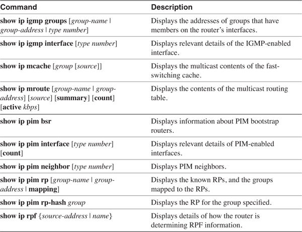
Table 6-3 Important debug Commands for Troubleshooting IP Multicast
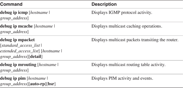
Using mrinfo
The mrinfo command enables you to observe a router’s multicast connections and the details of those connections. The command is a part of the tools originally made available as part of mrouted for testing routers in the MBone. Therefore, the command is very useful in multivendor domains. Take, for example, the topology in Figure 6-10.
Figure 6-10 This Topology Is Used Throughout the Troubleshooting Examples
In Example 6-55, mrinfo is used at router Sombrero. The first line of the output shows the address used as the source of the query, the Cisco IOS Software version running on the router, and a number of flags. Table 6-4 lists the possible flags and their meanings. The next two lines of output show multicast interfaces on the router and any peers that the router may have. On the second line, Sombrero’s interface 192.168.10.1 has no peers, indicated by the 0.0.0.0. The 1/0 indicates that the interface has a metric of 1 and that there is no TTL threshold set. PIM is running on the interface, the router is an IGMP querier for the attached subnet, and the subnet is a leaf network (that is, no multicast traffic will transit the network to another multicast router). The third line shows that Sombrero’s interface 192.168.200.1 has a peer at address 192.168.200.2 (router Beret), the metric of the interface is 1, there is no TTL threshold, and PIM is running.
Example 6-55 The IP Multicast Connection Information for Sombrero in Figure 6-10
Sombrero#mrinfo
192.168.10.1 [version 12.1] [flags: PMA]:
192.168.10.1 -> 0.0.0.0 [1/0/pim/querier/leaf]
192.168.200.1 -> 192.168.200.2 [1/0/pim]
Sombrero#
Table 6-4 Flags Associated with the mrinfo Command
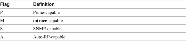
The true usefulness of mrinfo, however, is that you can use the command to query other routers in the domain. In Example 6-56, the command is used at Sombrero to query Boater, by specifying one of Boater’s IP addresses (in this case, its loopback address). Note that the flags indicate that SNMP is enabled on this router, whereas it is not on Sombrero. The router has five multicast-enabled interfaces, two of which are on leaf networks and three of which have PIM peers. A check of Figure 6-10 shows that this information is accurate.
Example 6-56 mrinfo Is Used at Sombrero to Query Boater About Its Multicast Peers
Sombrero#mrinfo 192.168.224.7
192.168.224.7 [version 12.1] [flags: PMSA]:
192.168.14.1 -> 0.0.0.0 [1/0/pim/querier/leaf]
192.168.15.1 -> 0.0.0.0 [1/0/pim/querier/leaf]
192.168.203.1 -> 192.168.203.2 [1/0/pim]
192.168.206.1 -> 192.168.206.2 [1/0/pim]
192.168.204.1 -> 192.168.204.2 [1/0/pim]
Sombrero#
In Example 6-57, routers Derby and Fez are queried. These two routers share an Ethernet connection, and comparing the results of the queries shows that Derby (192.168.224.4) is the IGMP querier on that subnet.
Example 6-57 Derby (192.168.224.4) and Fez (192.168.224.5) Are Queried from Sombrero
Sombrero#mrinfo 192.168.224.4
192.168.224.4 [version 12.1] [flags: PMA]:
192.168.12.2 -> 192.168.12.1 [1/0/pim/querier]
192.168.205.1 -> 192.168.205.2 [1/0/pim]
192.168.206.2 -> 192.168.206.1 [1/0/pim]
Sombrero#mrinfo 192.168.224.5
192.168.224.5 [version 12.1] [flags: PMA]:
192.168.12.1 -> 192.168.12.2 [1/0/pim]
192.168.205.2 -> 192.168.205.1 [1/0/pim]
192.168.204.2 -> 192.168.204.1 [1/0/pim]
192.168.201.2 -> 192.168.201.1 [1/0/pim]
Sombrero#
Using mtrace and mstat
Another useful tool is the mtrace command, which enables you to trace the RPF path from a specified destination to a specified source. Like mrinfo, mtrace is a UNIX-based MBone tool and can be used in multivendor domains. And also like mrinfo, you can issue the command from any router in the domain—you do not have to be on any router along the RPF path.
When the command is issued, you specify a source address and a destination address. A trace request is sent to the destination, which then uses a unicast trace to the source. The first-hop router on the path toward the source unicasts the results of the trace to the querying router.
Example 6-58 shows an example where a request is issued at Sombrero to trace the RPF path from Derby’s 192.168.12.2 interface to Turban’s 192.168.11.1 interface. Remember, because this is a reverse-path trace, Turban’s interface is the source and Derby’s interface is the destination. The output begins at the destination address and displays each intermediate router until the source is reached. The number of hops from the source is indicated, as is the multicast protocol used on that hop.
Example 6-58 mtrace Is Used to Examine the RPF Path from Destination 192.168.12.2 to Source 192.168.11.1
Sombrero#mtrace 192.168.11.1 192.168.12.2
Type escape sequence to abort.
Mtrace from 192.168.11.1 to 192.168.12.2 via RPF
From source (?) to destination (?)
Querying full reverse path...
0 192.168.12.2
-1 192.168.12.2 PIM [192.168.11.0/24]
-2 192.168.206.1 PIM [192.168.11.0/24]
-3 192.168.203.2 PIM [192.168.11.0/24]
-4 192.168.11.1
Sombrero#
Aside from the obvious use of isolating multicast routing failures, mtrace has an additional use of enabling you to examine multicast behavior before you turn up live multicast traffic on your internetwork. Notice in Figure 6-10 that no multicast sources or group members are indicated. Suppose you are going to turn up a multicast source attached to Boater, with an address of 192.168.14.35. This source will originate multicast traffic for group 235.100.20.18, and there will be group members at addresses 192.168.12.15, 192.168.10.8, and 192.168.11.102. Example 6-59 shows the results.
Example 6-59 mtrace Can Be Used to Test the RPF for Source, Destination, and Group Addresses That Do Not Yet Exist in the Multicast Domain
Sombrero#mtrace 192.168.14.35 192.168.12.15 235.100.20.18
Type escape sequence to abort.
Mtrace from 192.168.14.35 to 192.168.12.15 via group 235.100.20.18
From source (?) to destination (?)
Querying full reverse path...
0 192.168.12.15
-1 192.168.201.2 PIM [192.168.14.0/24]
-2 192.168.204.1 PIM [192.168.14.0/24]
-3 192.168.14.35
Sombrero#mtrace 192.168.14.35 192.168.10.8 235.100.20.18
Type escape sequence to abort.
Mtrace from 192.168.14.35 to 192.168.10.8 via group 235.100.20.18
From source (?) to destination (?)
Querying full reverse path...
0 192.168.10.8
-1 192.168.10.1 PIM [192.168.14.0/24]
-2 192.168.200.2 PIM [192.168.14.0/24]
-3 192.168.202.2 PIM [192.168.14.0/24]
-4 192.168.203.1 PIM [192.168.14.0/24]
-5 192.168.14.35
Sombrero#mtrace 192.168.14.35 192.168.11.102 235.100.20.18
Type escape sequence to abort.
Mtrace from 192.168.14.35 to 192.168.11.102 via group 235.100.20.18
From source (?) to destination (?)
Querying full reverse path...
0 192.168.11.102
-1 192.168.202.2 PIM [192.168.14.0/24]
-2 192.168.203.1 PIM [192.168.14.0/24]
-3 192.168.14.35
Sombrero#
The traces in Example 6-59 specify the multicast group along with the source and destination addresses. Although the RPF path would normally be the same for all groups, specifying the group can prove useful in situations where scoping or RP filtering affects the path taken. When no group is specified, as in Example 6-58, the group address 224.2.0.1 (the MBone audio group address) is used by default.
mstat is an adaptation of mtrace and provides not only a trace of the path from a source to a group destination, but also provides statistics about the path. Example 6-60 shows an example where a trace is again requested from source 192.168.14.35 to destination 192.168.10.8 for group 235.100.20.18. Comparing the output in Example 6-60 to the output for the same trace in Example 6-59, you can see that mstat provides not only packet statistics but also a more detailed view of the entire path.
Example 6-60 mstat Provides a More-Detailed Trace of Group Traffic from a Source to a Destination
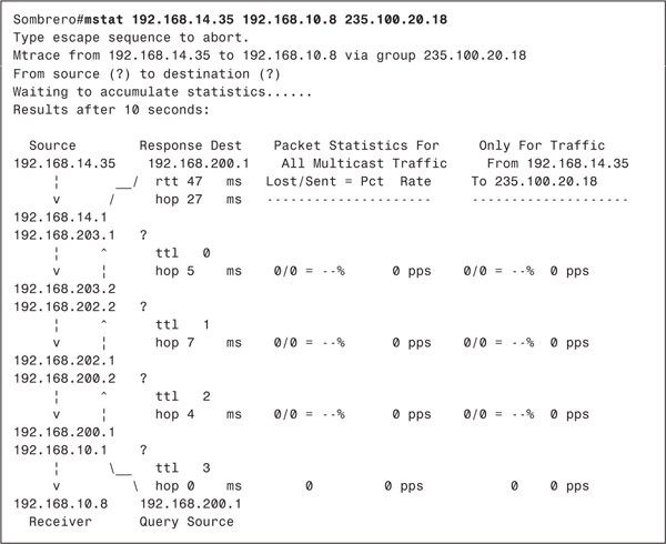
Reading from bottom to top, the display in Example 6-60 shows the query source and response destination, which in this example are both 192.168.200.1 (Sombrero). Notice that there is an ASCII representation of arrows, showing that Sombrero has sent the query to 192.168.10.1 (in this case, its own interface). The reverse path is then traced to the interface on Boater to which the source would be attached, and the response to the query is then sent to Sombrero. At the far left of the display, ASCII arrows also indicate the path multicast traffic will take from the source to the destination. At each hop, the ttl and hop statistics can be a little misleading. ttl actually shows the number of hops from that point to the source, whereas hops shows the delay (in milliseconds) between hops. Notice that the round-trip time (rtt) is indicated below the response destination. Statistics are then shown for all multicast traffic and for the (S, G) pair specified in the command. The first statistic compares the number of packets dropped to the number of packets sent. The second statistic shows the total traffic rate in packets per second. In Example 6-59, all these statistics are zero, of course, because no traffic has passed from the source to the destination. In fact, the source and destination do not even exist yet.
In Example 6-61, the proposed hosts have been installed, the source is generating traffic, and the group member has joined. You can now observe the packet-per-second rates and the drop statistics. An important point to keep in mind when using mstat is that the delay times between routers are valid only if the routers’ clocks are synchronized.
Example 6-61 The Same mstat Command Is Used After Multicast Traffic Has Begun Between the Source and Destination
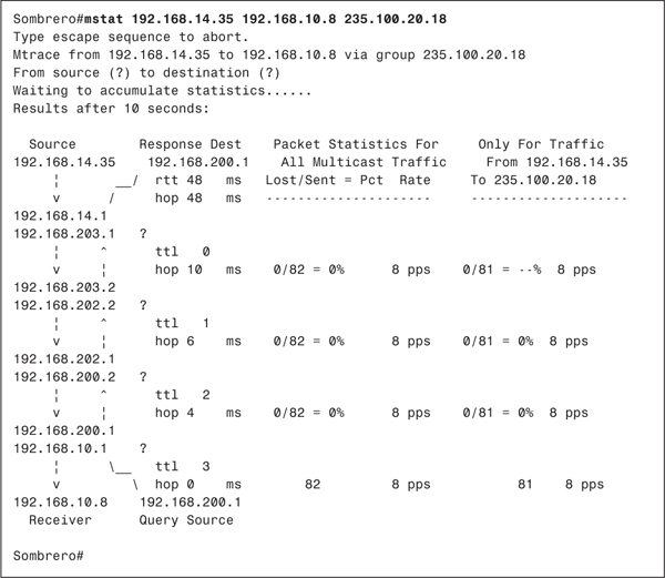
Example 6-62 shows what the display might look like if the clocks are not in sync. The trace information and packet rates are still valid, but the delay times for the individual hops are obviously nonsensical. Also in Example 6-62, you can see that one packet has been lost on the hop between Turban and Beret. This may or may not represent a problem; the only way to know is to run several iterations of mstat and observe whether the packet loss is consistent. If so, further investigation using debugging may be required.
Example 6-62 If the Routers’ Clocks Are Not Synchronized, the Delays Shown for the Router Hops Are Meaningless
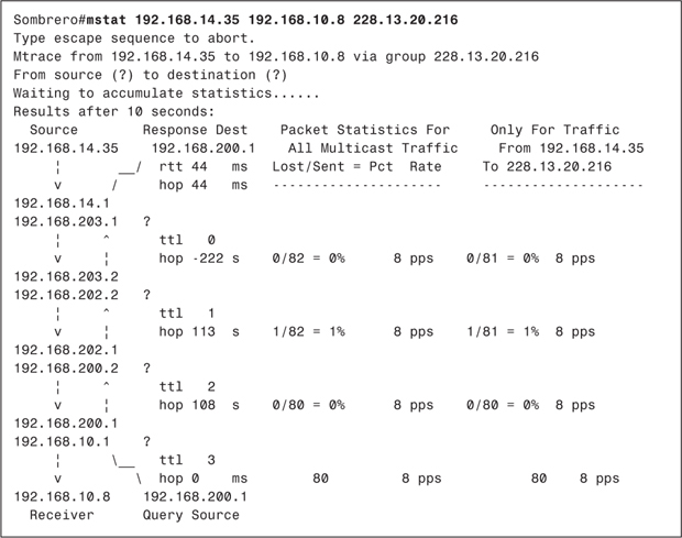
Lastly, you may encounter a situation in which mstat shows a negative number of lost packets such as, -3/85. The "negative packet loss" in fact represents a packet gain. In other words, extra packets have been received. This may signify a loop and warrants further investigation.
Looking Ahead
You now have a good grasp of the basics of configuring IP multicast routing. As with unicast routing, however, as the multicast domain grows you are presented with problems of scalability and control. Chapter 7, "Large-Scale IP Multicast Routing," introduces you to tools and strategies for addressing the problems of large-scale multicast routing, from scoping domains to interdomain multicasting.
Configuration Exercises
1 What global Cisco IOS Software command is required to enable IP multicast routing?
___________________________________________________________________________
___________________________________________________________________________
___________________________________________________________________________
2 Show the commands that enable PIM on an interface in dense mode, sparse mode, and sparse-dense mode.
___________________________________________________________________________
___________________________________________________________________________
___________________________________________________________________________
3 Show the command to statically specify an RP with an address of 172.18.20.4.
___________________________________________________________________________
___________________________________________________________________________
___________________________________________________________________________
4 Write the configuration statements necessary to statically map groups 239.1.2.3 and 228.1.8.0 through 228.1.8.255 to RP 192.168.15.5, and group 239.6.7.8 to RP 192.168.20.10. Map all other groups to RP 192.168.25.1.
___________________________________________________________________________
___________________________________________________________________________
___________________________________________________________________________
5 All router interfaces shown in Figure 6-11 are running in sparse-dense mode. Show the relevant configurations in order for R1 to be the RP for only groups whose addresses begin with 226.13.0.0/24. R2 should only be the RP for groups whose addresses begin with 239.0.0.0/8. R3 is the mapping agent; ensure that the mapping agent will recognize only R1 and R2 as RPs, and only for the specified groups. All Auto-RP messages should have a TTL of 20.
Figure 6-11 The Topology for Configuration Exercises 5–8
___________________________________________________________________________
___________________________________________________________________________
___________________________________________________________________________
6 Given the configurations of Configuration Exercise 5, suppose a source originates traffic for group 228.23.14.135, and a member requests a join to that group. What will happen?
___________________________________________________________________________
___________________________________________________________________________
___________________________________________________________________________
7 Again referring to Figure 6-11, write the necessary configurations to enable the bootstrap protocol, making R1 and R2 C-RPs for the same group addresses described in Configuration Exercise 5. Make R3 the BSR, and make R4 a backup BSR.
___________________________________________________________________________
___________________________________________________________________________
___________________________________________________________________________
8 Write configurations for the topology in Figure 6-11 that allow multicast load balancing between source 172.16.1.75 and group member 172.16.2.100. Use unnumbered addressing on the tunnel interfaces, referencing E0, and assume the IGP is advertising those addresses.
___________________________________________________________________________
___________________________________________________________________________
___________________________________________________________________________
9 Examine the configurations of Homburg and Porkpie shown in the case study "Multicast Load Sharing." Each router is running OSPF in passive mode on the tunnel interfaces. Why?
___________________________________________________________________________
___________________________________________________________________________
___________________________________________________________________________
10 What is the purpose of the command ip pim spt-threshold 100 group-list 25?
___________________________________________________________________________
___________________________________________________________________________
___________________________________________________________________________
Troubleshooting Exercises
1 What is the output of Example 6-63 telling you?
Example 6-63 The Output for Troubleshooting Exercise 1
R1#
Turban#debug ip mpacket
IP multicast packets debugging is on
R1#
IP: s=192.168.14.35 (Serial0/1.307) d=228.13.20.216 len 573, mrouting disabled
IP: s=192.168.14.35 (Serial0/1.307) d=228.13.20.216 len 573, mrouting disabled
IP: s=192.168.14.35 (Serial0/1.307) d=228.13.20.216 len 573, mrouting disabled
IP: s=192.168.14.35 (Serial0/1.307) d=228.13.20.216 len 573, mrouting disabled
IP: s=192.168.14.35 (Serial0/1.307) d=228.13.20.216 len 573, mrouting disabled
IP: s=192.168.14.35 (Serial0/1.307) d=228.13.20.216 len 573, mrouting disabled
IP: s=192.168.14.35 (Serial0/1.307) d=228.13.20.216 len 573, mrouting disabled
IP: s=192.168.14.35 (Serial0/1.307) d=228.13.20.216 len 573, mrouting disabled
IP: s=192.168.14.35 (Serial0/1.307) d=228.13.20.216 len 573, mrouting disabled
IP: s=192.168.14.35 (Serial0/1.307) d=228.13.20.216 len 573, mrouting disabled
IP: s=192.168.14.35 (Serial0/1.307) d=228.13.20.216 len 573, mrouting disabled
IP: s=192.168.14.35 (Serial0/1.307) d=228.13.20.216 len 573, mrouting disabled
IP: s=192.168.14.35 (Serial0/1.307) d=228.13.20.216 len 573, mrouting disabled
___________________________________________________________________________
___________________________________________________________________________
___________________________________________________________________________
2 What is the output of Example 6-64 telling you?
Example 6-64 The Output for Troubleshooting Exercise 2
R2#
IP: s=192.168.13.5 (Ethernet0) d=227.134.14.26 len 583, not RPF interface
IP: s=192.168.13.5 (Ethernet0) d=227.134.14.26 len 583, not RPF interface
IP: s=192.168.13.5 (Ethernet0) d=227.134.14.26 len 583, not RPF interface
IP: s=192.168.13.5 (Ethernet0) d=227.134.14.26 len 583, not RPF interface
IP: s=192.168.13.5 (Ethernet0) d=227.134.14.26 len 583, not RPF interface
IP: s=192.168.13.5 (Ethernet0) d=227.134.14.26 len 583, not RPF interface
IP: s=192.168.13.5 (Ethernet0) d=227.134.14.26 len 583, not RPF interface
IP: s=192.168.13.5 (Ethernet0) d=227.134.14.26 len 583, not RPF interface
IP: s=192.168.13.5 (Ethernet0) d=227.134.14.26 len 583, not RPF interface
___________________________________________________________________________
___________________________________________________________________________
___________________________________________________________________________
3 What is the output of Example 6-65 telling you?
Example 6-65 The Output for Troubleshooting Exercise 3
R3#debug ip mpacket
IP multicast packets debugging is on
R3#
IP: s=172.16.3.50 (Serial0.405) d=224.0.1.40 (Serial0.407) len 52, mforward
IP: s=172.16.3.50 (Ethernet0) d=224.0.1.40 len 62, not RPF interface
IP: s=172.16.3.50 (Ethernet0) d=224.0.1.39 len 62, not RPF interface
IP: s=172.16.3.50 (Serial0.405) d=224.0.1.39 (Serial0.407) len 52, mforward
___________________________________________________________________________
___________________________________________________________________________
___________________________________________________________________________
4 In Figure 6-12, which of the four routers is the PIM-designated router?
Figure 6-12 The Topology for Troubleshooting Exercises 4, 5, and 6
___________________________________________________________________________
___________________________________________________________________________
___________________________________________________________________________
5 In Figure 6-12, which router is sending IGMPv2 queries to the group member?
___________________________________________________________________________
___________________________________________________________________________
___________________________________________________________________________
6 Table 6-5 shows the unicast routes to source 172.16.12.18 in Figure 6-12. Which router is the PIM forwarder?
Table 6-5 Unicast Routes to 172.16.12.18 in Figure 6-12
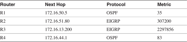
___________________________________________________________________________
___________________________________________________________________________
___________________________________________________________________________
7 Example 6-66 shows an RPF trace taken from the PIM domain in Figure 6-10, which is running RIP-2 as its unicast IGP. Does this trace indicate a possible problem?
Example 6-66 The mtrace for Troubleshooting Exercise 7
Sombrero#mtrace 192.168.14.35 192.168.10.8 235.1.2.3
Type escape sequence to abort.
Mtrace from 192.168.14.35 to 192.168.10.8 via group 235.1.2.3
From source (?) to destination (?)
Querying full reverse path...
0 192.168.10.8
-1 192.168.10.1 PIM [192.168.14.0/24]
-2 192.168.200.2 PIM [192.168.14.0/24]
-3 192.168.201.2 PIM [192.168.14.0/24]
-4 192.168.204.1 PIM [192.168.14.0/24]
-5 192.168.14.35
Sombrero#
___________________________________________________________________________
___________________________________________________________________________
___________________________________________________________________________