CSPM Installation
This section covers the installation requirements for CSPM.
Before you install CSPM, you have to ensure that the installation system meets the hardware and software requirements. This section assumes that you are using version 2.2 of the CSPM. If you are using a different version, you should consult your documentation to ascertain the requirement differences.
Hardware Requirements
The target host for your CSPM system must meet the minimum hardware requirements to protect the integrity and functionality of the system that you install. However, you should always consider your network topology, the number of policy enforcement points you intend to manage, and your performance requirements for command distribution and monitoring when reviewing the minimum hardware requirements.
For example, the Policy Server is a multithreaded application that would benefit from multiple CPUs and available memory on a single host. Enhancing the Policy Administrator host would not necessarily optimize the GUI performance. The minimum hardware requirements may be sufficient for a standalone or client-server system, but they are not optimal for a distributed system. To ensure optimal performance, you should install CSPM on hosts that exceed the minimum hardware requirements.
Minimum Hardware Requirements
The minimum hardware requirements to run the CSPM are as follows:
200 MHz Pentium processor
96 MB of RAM
2 GB free hard drive space
One or more properly configured network adapter cards
1024 by 768 video adapter card capable of at least 64 K color
CD-ROM drive (preferably Autorun-enabled)
Modem (optional for pager notifications)
Mouse
SVGA color monitor
Software Requirements
You can install the CSPM feature sets on any host that meets the minimum hardware requirements and that also runs Windows NT 4.0. To install version 2.2, you must be using Microsoft Windows NT 4.0 with Service Pack 6a installed. CSPM will not install on any other Service Pack built on Windows NT 4.0 or on a system running Microsoft Windows 2000.
The Policy Administrator feature set can also be installed on a host that runs Windows 95 or Windows 98.
Requisite Software
You cannot access the setup program unless the target host on which you are installing CSPM has the following requisite software properly installed:
Service Pack 6a for Windows NT (to update files in the operating system)
Microsoft Internet Explorer version 5 (for displaying system-generated reports)
HTML Help 1.3 Update (for viewing online HTML-based help topics)
The Autostart utility automatically searches the target host for these requirements and lists the ones that you must install before proceeding with the setup program. You can install all three pieces of software from the Autostart panel.
Planning your Installation
Once you ascertain that you have met the hardware and software installation criteria, you can progress to planning the installation.
Before you can plan the installation, you have to fully understand three topics related to CSPM:
Policy enforcement points
Feature sets
Installation options
Policy Enforcement Points
A policy enforcement point is defined as a networking device that can alter the traffic flow from one network to another.
Concerning the CSPM, a policy enforcement point can be any device that CSPM manages through the distribution of policies.
These policy enforcement points can be dedicated firewalls, such as the Cisco Secure PIX Firewall, router firewalls, or VPN gateways. Router firewalls are Cisco routers that are running the Cisco IOS Firewall, and VPN gateways are Cisco routers that are running the Cisco IOS Firewall with the IPSec VPN feature set.
Only specific versions of the Cisco Secure PIX Firewall and Cisco IOS Firewall will work with CSPM and in different ways. One restriction is with the PIX Firewall. All versions of the PIX software prior to 5.1(x) require the managed interface to be available on the inside interface. With version 5.1(x) and later, you can manage the PIX Firewall from any available interface on the PIX.
Table 8-1 shows the supported policy enforcement points and their interface dependencies.
| Policy Enforcement Point | Supported Version | Managed Interface Dependency |
|---|---|---|
| Cisco Secure PIX Firewall | 4.2(4) | Inside |
| 4.2(5) | Inside | |
| 4.4(x) | Inside | |
| 5.1(x) | None | |
| 5.2(x) | None | |
| Cisco Router Firewall | IOS 12.0(5)T | None |
| Cisco VPN gateway | IOS 12.0(5)XE | None |
| IOS 12.0(7)T | None | |
| IOS 12.1(1)T, E, XC | None | |
| IOS 12.1(2), T, (2) T, E, XH, (3) T, X1 |
The installation of the policy enforcement points is not included in the system. Each policy enforcement point must be configured to facilitate management from the CSPM. These configurations are called the bootstrap settings.
The bootstrap settings are very important for achieving communication between the policy server and the policy enforcement points. The bootstrap settings for each device are explained in detail in the section “Installation Procedures” later in this chapter.
Feature Sets
The CSPM system is composed of multiple subsystems. Each of these subsystems provides a specific functionality that makes up the whole CSPM product. A feature set is defined as a collection of these subsystems, which are offered at installation time as installable options. These also are related to the specific installation options that are discussed in Chapter 9, “Cisco Secure Access Control Server (ACS).” The options are dictated largely by the network topology and number and location of the policy enforcement points.
The five feature sets are as follows:
Policy Administrator
Policy Server
Policy Monitor
Policy Proxy
Policy Proxy-Monitor
Policy Administrator
The Policy Administrator feature set is the primary GUI for policy definition, enforcement, and auditing for your CSPM system.
Policy Server
The Policy Server feature set contains the database subsystem. This subsystem is the main data store for all of the system configuration data and audit records. Besides the database subsystem, the reporting and generation subsystems are also within the Policy Server feature set.
The reporting subsystem is responsible for generating the on-demand and scheduled reports associated with CSPM.
The generation subsystem compiles the global policy into a collection of intermediate policies that are applied to the specific policy enforcement points.
The Policy Server feature set also includes the Policy Administrator, Policy Proxy, Policy Proxy-Monitor, and Policy Monitor feature sets.
NOTE
The Policy Server feature set always has to be the first feature set installed. The database key generated during this installation is required during installation of all other feature sets.
Policy Monitor
The Policy Monitor feature set contains the monitoring subsystem and a secondary database.
The monitoring subsystem is responsible for collecting all of the audit records from the policy enforcement points and processing this data to generate notification alerts appertaining to specific conditions.
The secondary database exchanges status and summary audit records with the primary database that is installed with the Policy Server feature set.
The Policy Administrator feature set is installed when you install the Policy Monitor feature set.
Policy Proxy
The Policy Proxy feature set contains the proxy subsystem and another secondary database.
The proxy subsystem maps and translates the intermediate policy into a device-specific rule set required by the managed policy enforcement points on your network.
The secondary database maintains a local copy of the intermediate policies and stores the system events that are generated by the proxy subsystem. This data is then synchronized with the Policy Server on the Policy Server host.
The Policy Administrator feature set is installed when you install the Policy Proxy feature set.
Policy Proxy-Monitor
The Policy Proxy-Monitor feature set basically combines the functionality of the proxy and monitoring subsystems. This allows you to have a distributed system with a reduced number of required hosts on which to run the feature sets.
The Policy Administrator feature set is installed when you install the Policy Proxy-Monitor feature set.
Installation Options
There are four ways of installing the CSPM. The method you choose largely depends on your network topology and the number of devices to be managed.
The four types of installation are:
Standalone system
Client-server system
Distributed system
Demo system
Standalone System
As you would expect, a standalone system installation is when the CSPM is installed on a single host. All of the CSPM functions are carried out on this single host.
A standalone installation should be used in a small office environment. This would normally be located on one site with no policy enforcement points located at the remote end of a WAN link. The centralized location of the installation enforces centralized management of the security policy.
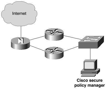
Figure 8-2 shows a network topology where a standalone installation would suffice.
Figure 8-2. Sample Standalone Installation Network

As you can see in Figure 8-2, this is a small office with a small number of policy enforcement points. This topology is suited to the standalone installation and is scalable to the client-server installation as the network grows.
Client-Server System
The client-server installation is when you install the CSPM Policy Server feature set on one host and the Policy Administrator feature set on one or more different hosts in the network. The client-server architecture is followed in that the Policy Server is installed on a single host, the server, which can be administered from clients in various network locations.
A client-server installation is normally required for larger networks than those served by standalone systems. One key point is the management of the security policy. Standalone systems are necessary when only centralized management and administration is required. When management is decentralized and numerous separate entities require localized administration, it is necessary to scale to the client-server model. This model also fits into a multioffice topology, where multiple policy enforcement points are located throughout the entire network.
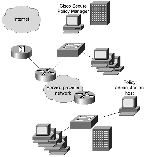
Figure 8-3 shows a network topology where a client-server installation is required.
Figure 8-3. Sample Client-Server Installation Network

You can see in the topology in Figure 8-3 that each site has its own policy enforcement point, and the remote offices each have their own policy administration host.
Distributed System
You should recall that the standalone system has all of the CSPM feature sets installed on one host, and the client-server system is theoretically the same, except that the Policy Administrator feature set can be installed on numerous hosts across the network.
The distributed system expands the client-server model by allowing distribution of other CSPM feature sets to multiple hosts on the network.
With this model, you have to install the Policy Server feature set on a single host, which acts as the main policy server. The other features such as the Policy Proxy, Policy Proxy-Monitor, and Policy Monitor can all be installed on any number of additional hosts. This system distributes the components and allows these hosts to assume responsibility for monitoring and proxy functionality for a portion of the enterprise network.
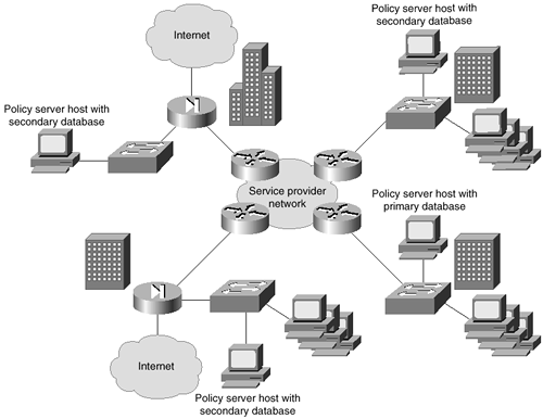
Figure 8-4 shows a network topology where a distributed installation is required.
Figure 8-4. Sample Distributed Installation Network

As you can see, the network in Figure 8-4 is spread over three main offices. Each office is classed as a separate administrative entity because of the internal and external protected links. You can see that each site is connected by the company intranet, and each site has its own external links. Internet access is provided through the company headquarters. This model gives every site its own Policy Administrator host, as well as a Policy Proxy-Monitor host that holds the secondary database. This model allows 24/7 management of security services throughout the corporate network from multiple locations. The distributed installation also provides better performance of the CSPM system by off-loading critical functions to different servers. In offices that contain several policy enforcement points, dedicated Policy Monitor and Policy Proxy hosts are deployed.
Demo System
In addition to installing CSPM in a live environment, you can install it in demo mode. This will only install it on a single host; the full feature set and the Policy Administrator feature are installed with various demonstration files. Demo mode's main purpose is to allow you to make a demo installation to explore the Policy Administrator interface and features without having to install a live system. This mode can be used for appraising the system or to train staff in the correct use of the CSPM's many features.
Installation Procedures
Now that you have seen the installation procedures and components, this section will concentrate on the actual software installation and policy enforcement point configuration. Remember that each policy enforcement point requires specific settings to enable communication with CSPM and to allow CSPM to fully and dynamically manage the policy enforcement point. These settings are called the bootstrap settings.
Software Installation
CSPM is provided on a CD-ROM that has to be installed to your host's hard disk for the application to function. CSPM will not operate from the CD drive.
This chapter will not examine the full installation process. The process is fully documented on Cisco Connection Online at www.cisco.com and also in the documentation provided with the CSPM product.
Policy Enforcement Point—Bootstrap Settings
For the CSPM to connect to and configure the policy enforcement points, some basic commands have to be added to the configuration of the policy enforcement points.
These commands enable communication and allow CSPM to take over the management of the device to control it as a policy enforcement point.
NOTE
Note that once you have enabled a device to become a policy enforcement point by bootstrapping, you must never connect to the device using the CLI and make manual changes to the configuration.
The devices must be either manually controlled or controlled by CSPM as a policy enforcement point. If you were to connect manually and add lines of configuration commands, the policy manager would remove these lines when it next synchronized the configuration.
There are different bootstrap settings required depending on whether the device is a PIX Firewall or a router with the Cisco IOS Firewall installed. Each is discussed separately in the following two sections.
Cisco Secure PIX Firewall Bootstrapping
You must connect to the PIX Firewall using a console cable to the console port and a terminal application. Once connected, follow these steps in order to configure the initial bootstrap settings:
This concludes the bootstrapping of the Cisco Secure PIX Firewall. The PIX Firewall is now ready to be managed by the CSPM.
Cisco IOS Firewall Bootstrapping
You must connect to the router running the Cisco IOS Firewall using a console cable to the console port and a terminal application. Once connected, follow these steps to configure the initial bootstrap settings.
This concludes the bootstrapping of the Cisco IOS Firewall-enabled router. The device is now ready to be managed by the CSPM.
