
Chapter 11. Address Translation
Part IV, “Stateful and Advanced Filtering Technologies,” dealt with stateful filtering of traffic as well as filtering of web traffic. This part deals with address translation: why it is necessary, how it is done, problems that address translation introduces, and address-translation features of the Cisco IOS. This chapter focuses on the basics of address translation: the different kinds of address translation available and how they are configured on a Cisco router. The next chapter deals with address translation issues and Cisco IOS features that you can use to solve these problems.
Address Translation Overview
One of the issues that you will face when designing a network is ensuring that all your devices have an IP address. Each device needs an IP address for sending and receiving traffic, as well as for remote management. With a shortage of public IP addresses for accessing the Internet, this presents a problem for assigning addresses to devices to allow communications. Some type of solution is needed.
One of the problems that the Internet faces is IP address depletion. As a long-term solution, IPv6 is addressing this. However, a lot of manpower and money is required to covert from IPv4 to IPv6. As a short-term solution, IETF defined two standards: RFC 1918 and 1631. These standards set aside a range of public IP addresses and allow anyone to use them; they also translate these addresses to public addresses when they leave a company’s network. The following sections discuss these standards.
Private Addresses
RFC 1918 sets aside a block of addresses that any network can use, commonly called private addresses. Table 11-1 lists the address class as well as the range of addresses that RFC 1918 sets aside for the class. With this RFC, 1 Class A, 16 Class B, and 256 Class C addresses are set aside for intracompany use. As you can see from this list of addresses, you have more than 17 million at your disposal—more than enough to assign addresses to all your internal devices.

These addresses work fine for intracompany communications, in which one device in a company accesses another device in the same company. However, using private addresses presents problems when two companies want to share information but they are both using the same private address space. Figure 11-1 shows a simple example of this problem. In this example, two companies, A and B, are both using network 10.0.0.0/8. In Company A, an internal user (A) wants to access a server in Company B. You will notice, that in this example, this presents a problem: Both networks are using network 10.0.0.0/8, and both have overlapping addresses: 10.1.1.1. The two networks cannot communicate with each other.

Address Translation
To solve this communication problem, IETF introduced RFC 1631. This RFC defines address translation, translating addressing information in a packet from one number to another. Typically, this is used to translate private addresses to public ones, and vice versa. This translation process commonly is referred to as Network Address Translation (NAT).
You might need to use private IP addresses for these reasons:
• Your current ISP assigned you a limited number of public addresses, but not enough to assign to all of your devices.
• You currently have enough public addresses, but you are changing ISPs and your new ISP will not support your old public address space.
• You need to merge two networks, which, unfortunately, are using the same address space.
• You currently are using someone else’s assigned public addresses.
• You want to set up load balancing by using a single virtual IP address to represent multiple devices.
• You want to have better control over traffic entering and leaving your network.
Advantages of Address Translation
Address translation has both its advantages and disadvantages. Take a look at its advantages first:
• You have access to 1 Class A, 16 Class B, and 256 Class C networks, totaling more than 17 million addresses.
• If you change ISPs, your work is simplified. You need to change only the address-translation rules on your address-translation device; you do not have to change addresses on specific devices.
• Your ISP drops packets with private addresses in them, giving you tighter control over traffic leaving your network. If the private addresses are not translated as they leave your network, your ISP drops these packets.
• The internal structure of your network is hidden from outside eyes.
Disadvantages of Address Translation
Address translation also has its share of disadvantages, including the following:
• When performing address translation, your address-translation device introduces delay in the packet stream. The address-translation device must change addressing information in the packet and recompute checksum information.
• The more translations your address translation device needs to support, the greater burden this places on the device. This can create scalability issues in large networks.
• It is more difficult to troubleshoot problems because the source and possibly destination are using translated addresses. Therefore, when you look at an IP address in a packet, you cannot necessarily be sure whether this is the address physically assigned to the device or whether it is a translated address.
• Even though address translation provides tighter security, it allows people to hide their identities through address translation, making it more difficult to track down the source of an attack.
• Some applications embed addressing information in the payload contents. This presents a problem with address-translation devices, which typically translate addressing information only for the IP and, possibly, TCP or UDP headers. If an address-translation device does not translate embedded addressing information, and a device attempts to use the untranslated information, it cannot connect to its destination.
Given the advantages and disadvantages of address translation, you must take care in deciding when you need to use address translation and what it will encompass.
How Address Translation Works
Now that you have a basic understanding of what address translation is, take a look at some of the terms used in address translation, as well as the different kinds of address translation. Many different kinds of devices, such as firewalls, routers, and even servers, can perform address translation (Cisco routers have supported address translation since Cisco IOS 11.2). The following sections will help you become more familiar with these concepts.
Terms Used in Address Translation
Before you can understand how address translation is performed by a device, you first need to become familiar with some terms commonly used with address translation. Table 11-2 explains some basic terms used with address translation; Table 11-3 explains some common types of address translations.


Performing Address Translation
Many different types of address translation exist, as you saw in Table 11-3. This section covers the mechanics and the variations of the different kinds in this table, focusing on specific address translation types.
Network Address Translation
The most common form of address translation is the translation of one IP address to another. Two common forms of this translation exist:
• Changing a source inside local address to a source inside global address
• Changing a destination inside global address to a destination inside local address
You can see how this is done by examining Figure 11-2. In this example, the network on the left is using private addresses (10.0.0.0/8), and the router is performing address translation for these addresses. In Step 1, 10.0.0.1 creates a packet destined for 200.1.1.1. In Step 2, the router receives the packet and performs address translation on the source address. The router first looks at its static configuration for address translation. If it finds a match, it uses the inside global address as the replacement; if not, it uses a dynamic assignment method by checking to see whether this packet should be translated and, if so, what pool of addresses the router should use. In this example, the source IP address was translated from 10.0.0.1 to 192.1.1.1. When the destination device (200.1.1.1) receives the packet in Step 3, it thinks that it is talking to 192.1.1.1 and thus replies to this address. As mentioned earlier, one advantage or disadvantage of this is that the source is anonymous, depending on your view; in this example, the destination has no idea who the real source is. In Step 4, the router receives the packet and performs its address-translation process again. In this instance, though, it changes the destination IP address in the packet header: 192.1.1.1 to 10.0.0.1.

Note
One important thing to point out concerning NAT (versus PAT) is that, for each device that sends packets through the address-translation device, you need a separate inside global IP address. For example, if you have simultaneous outbound connections from 500 inside devices, you need 500 global addresses either statically configured or dynamically assigned through an address pool on the address-translation device. Each device needs a unique inside global IP address. Because you might have thousands of internal devices, but only a limited number of public addresses, NAT typically is not used to assign IP addresses for internal devices as they make outbound connections. Instead, NAT is used to assign addresses to devices that external users need access to, such as internal DNS servers, web servers, e-mail servers, FTP servers, and other types of public resources.
Overlapping Addresses
Sometime during your life as a network administrator, you probably will need to connect two networks, but they happen to be using the same address space. Obviously, this creates connectivity problems. As an example, look at Figure 11-3. Companies A and B are using 10.0.0.8/24. This would be okay if both companies used different subnet numbers, with A using 10.1.x.x and Company B using 10.2.x.x. However, as you can see in this example, both companies are using some of the same networks and addresses. This presents a connectivity problem. How can 10.0.0.1 in Company A send information to 10.0.0.1 in Company B?

To overcome this problem, you must do one of two things:
• Readdress one of the two networks (or both networks)
• Use address translation
Address translation can be used to solve this problem. In this example, the router connected to Company A translates the local IP addresses to an address in the 172.16.0.0/16 network. Company B’s router translates its inside local addresses to 172.17.0.0/16. Therefore, from the two companies’ perspectives, the networks look like 172.16.0.0/16 and 172.17.0.0/16. However, there is one issue with this type of address translation: Normally, devices use names to access other devices, and they rely on DNS to resolve names to IP addresses.
Take a closer look at this problem. Assume that the device on Company A (10.0.0.1) wants to access www.companyb.com, which is a web server. It does a DNS lookup, and the DNS server in Company B replies with 10.0.0.1. Company A’s device then uses this IP address as a destination and tries to set up a connection to itself. To solve this issue, address-translation devices also need to inspect DNS replies and fix the DNS replies with the appropriate address, commonly referred to as DNS doctoring. In this example, Company B’s address translation device would have to change the DNS reply address of www.companyb.com from 10.0.0.1 to 172.17.x.x, an address that does not overlap with Company A.
Tip
Use address translation as only a temporary solution when solving overlapping addresses. In other words, use address translation to solve the initial connectivity problem, but begin readdressing one or both networks so that address translation is not necessary. Remember that address translation has its deficiencies. If these networks constantly will be communicating with each other, you want to take address translation out of the picture. Plus, eventually removing address translation makes it much easier to implement, enforce, and troubleshoot your policies.
Also, many companies require vendors to use specific addresses with the VPN when using extranet VPNs. In this situation, either you or the vendor must translate the addresses. Sometimes this is done for security reasons, but in many cases, it is to ensure that overlapping addressing does not cause a problem.
Address Overloading
Address overloading, commonly called PAT, uses one or more inside global IP address to encompass all inside devices. To differentiate between the different internal connections, PAT ensures that the TCP or UDP source port numbers in the segment header are unique. With this capability, an address-translation device can handle thousands of inside local addresses with a single global address.
Note
Theoretically, this would enable you to map 65,536 addresses to a single address because the source port field in a TCP or UDP segment is 16 bits in length. Realistically, though, only about 4000 devices can share a single global IP address because certain port numbers are not used or are not recommended for use. Therefore, if you have 6000 devices that need outside access, you need two inside global addresses for PAT.
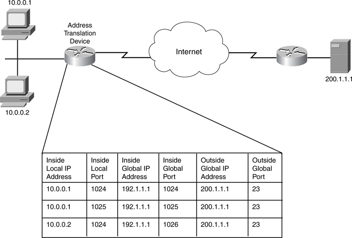
Take a look at an example of how address overloading works. In Figure 11-4, the network on the left is using PAT to translate inside local addresses to one inside global address: 192.1.1.1. For the first connection, 10.0.0.1 Telnets to 200.1.1.1 using a source TCP port number of 1024. As you can see from the first entry in the router’s address-translation table, the router translated the source IP address to 192.1.1.1 but left the source port number as is because this is the first connection; therefore, no other device is using the same source port number. 10.0.0.1 then makes another Telnet connection to 200.1.1.1. As a source port number, 10.0.0.1 chooses a number greater than 1023 that is not in use; in this instance, it chose 1025. As you can see from the second entry in the address-translation table, the router translated only the source address because the source port number is different from the one used in the first entry. For the third connection, a different device (10.0.0.2) Telnets to the same destination. In this instance, the source port number happens to be the same as the first connection; therefore, the address-translation device changes the source address (10.0.0.2 to 192.1.1.1) as well as the source port number (1024 to 1026). From this translation table, the router easily can determine, based on returning traffic, how it should undo the address-translation process.
Tip
Note that NAT and PAT are not mutually exclusive. Where NAT is used to perform address translation of inside addresses that external users need to access, PAT typically is used to conserve addresses as inside users access external resources. As an example, assume that your ISP assigned you six public IP addresses. If you had a DNS server, a web server, and an e-mail server, you would need three static NAT configurations for these devices, using up three addresses. This would leave you with three addresses. Assume that you had only 1000 devices that needed access to the Internet. In this example, you could use PAT with one of the remaining public addresses to allow outside access, still leaving you with two spare public IP addresses.
One issue with PAT is that it works fine for traffic that uses TCP and UDP as a transport. However, how can PAT work for applications or protocols that do not use TCP or UDP, such as ping, which uses ICMP? ICMP does not have port numbers. To solve this problem, a vendor typically uses a proprietary mechanism to place identifying information in either the packet header or the payload, to help undo translations for returning traffic. However, this assumes that the destination will include this information in the packet header or payload of returning traffic. Some vendors maintain a state table for this kind of translated traffic, keeping tabs on who generated what, thereby undoing the translation correctly for returning traffic. However, this can pose a problem if two inside devices send the same kind of information to the same destination device. For example, two internal devices simultaneously might ping the same destination device. In this example, the address-translation device could not rely on state information alone to undo the address translation; it would need some type of additional identification information in the returning packets.
Caution
PAT works fine with most TCP and UDP connections, but it can experience problems with other types of protocols, such as ICMP, IPSec (with either AH or ESP), PPTP, and others. There is no guarantee that a vendor will support a PAT process for non-TCP and non-UDP connections. In some instances, you might have to use NAT for devices that need to use other protocols, such as IPSec with ESP, when accessing external resources, instead of using PAT.
Traffic Distribution and Load Balancing
One of the commonly forgotten uses of address translation is the traffic distribution feature, commonly called load balancing. As an example, assume that you have a web server that contains content that is very popular on the Internet and that is getting thousands of hits every hour. Because of this traffic, load, the CPU processing on the server is very high and sometimes hits 100 percent, causing it to drop many connection requests and frustrating external users with poor download times. One solution to this problem is to buy a bigger, faster server. However, if you have ever been through this process, it is not simple to buy a new server, migrate the information to the old server, and then swap the old server for the new one.
Traffic distribution in address translation enables you to get around this upgrade process. Instead of swapping out an older server for a newer one, you can purchase a second server and simultaneously use both. At first, you might think that this would cause a problem because both servers have different IP addresses. You could have your DNS server respond in a round-robin fashion, to assign one address to one DNS request, the other address to a second request, and so on. This assumes that your DNS server supports this function; however, one downside to this approach is that the requesting client caches the DNS information and uses it repeatedly. This can lead to a disproportionate amount of traffic being sent to one of the two servers.
A better approach is to have an address-translation device perform this process. In Figure 11-5, the network on the left has two internal web servers that have exactly the same content. The internal DNS server advertises this content as being at 192.1.1.5, even though both servers have the content. When an external device accesses 192.1.1.5 on TCP 80, the address-translation device looks at the last translation that it made and then chooses the next IP address in the server pool for this request. As you can see in this example, the two external users use the two internal servers to obtain the same content.

Caution
Many different kinds of products, including Cisco IOS routers, perform traffic distribution. However, not all of them do this process equally. For example, some solutions just round-robin between the different server addresses, not checking to see if the server is actually available or checking the current load on the server. Some solutions actually check on the server’s status and use this when computing how it should perform traffic distribution. Using a Cisco IOS device is probably not the best load-balancing solution: The Cisco local director or content switches would provide a better solution.
Limitations of Address Translation
Even though address translation provides many solutions to your connectivity problems, especially when using private addresses, it does have limitations and restrictions.
For example, as mentioned with PAT, PAT does not work with all types of IP protocols. Here are some common limitations in which address translation might not or will not work:
• Many applications embed IP address and port number information in the payload. Unless an address-translation device is designed to look for this kind of information, these applications will fail when address translation is used. For example, ICMP, SNMP, DNS (replies and zone transfers), BOOTP and DHCP, routing updates, NetBIOS, and multimedia applications commonly include IP addressing in the payload of packets. Chapter 12, “Address Translation Issues,” discusses how a Cisco router deals with this issue.
• Address translation will not work if the headers of the packet or the segment are encrypted.
• Some vendors do not support address translation for multicast addresses (the Cisco IOS does, but that is beyond the scope of this book).
There are other limitations, but these three (especially the first) are the most common issues you will find when dealing with address translation.
Address Translation Configuration
The remainder of this chapter focuses on the setup of basic address translation on your router. Some of the issues of address translation and configuration solutions to these issues are left for the next chapter. As you will see in the rest of this chapter, you need to perform two basic steps, no matter what type of address-translation solution(s) you will implement:
• Define your address-translation policies.
• Define which interfaces are considered internal and external.
The following sections cover how to configure address translation for NAT, PAT, port address redirection, overlapping addresses, and basic load balancing.
Configuration of NAT
You can perform NAT translation either statically or dynamically:
• With a static NAT translation, you define a one-to-one mapping of inside local addresses to inside global addresses. Static inside NAT translation typically is done when you have an internal server with a private address, but you want to allow external users to access this service.
• With a dynamic NAT translation, you create a pool of inside global addresses that your internal devices will use when translating their inside local addresses. This typically is used for internal users accessing external resources, especially for connections that experience problems with PAT.
The following two sections discuss how to configure these two types of NAT.
Static NAT
With static NAT, you need to perform two tasks:
Step 1 Define your static translations.
Step 2 Specify which interfaces are internal and external.
To define your static translations, use the ip nat inside source static command:
Router(config)# ip nat inside source static inside_local_IP_address
inside_global_IP_address
This command creates the static mappings of inside local to inside global addresses. The first IP address that you list is the one that the Cisco IOS examines in the source of the IP packet. If it is found, the Cisco IOS translates the source address to the second address that you listed in this command.
Another form of this command enables you to map one network to another with the following syntax:
Router(config)# ip nat inside source static network
inside_local_IP_network_number inside_global_IP_network_number subnet_mask
This command is more user friendly because you do not have to map individual IP addresses: You can map one network to another, address for address. For example, if you have a local network of 192.168.1.0/24 and a global network of 192.1.1.0/24, each host address in the local network is mapped to the corresponding host address in the global network. For example, 192.168.1.1 maps to 192.1.1.1, and 192.168.1.2 maps to 192.1.1.2. For the subnet mask value, you can enter it either in dotted decimal, as in 255.255.255.0, or by number of bits, as in /24.
After you have created your address-translation entries, you must specify what interfaces are considered to be internal (inside) and which are considered external (outside). This is done with the ip nat {inside | outside} Interface command:
Router(config)# interface type [slot_#/]port_#
Router(config-if)# ip nat {inside | outside}
Note
By specifying which interfaces are inside and which are outside, you are influencing how address translation is performed by the router.
To help illustrate the use of this command, take a look at the network shown in Figure 11-6. In this example, I want to make two servers inside the network available to the outside world.

The basic static NAT configuration for this router is displayed in Example 11-1.
Example 11-1 Basic Example Using Static Inside NAT
Router(config)# ip nat inside source static 10.0.0.1 192.1.1.1
Router(config)# ip nat inside source static 10.0.0.2 192.1.1.2
Router(config)# interface ethernet0
Router(config-if)# ip nat inside
Router(config-if)# exit
Router(config)# interface ethernet1
Router(config-if)# ip nat outside
As you can see, 10.0.0.1 is assigned an inside global IP address of 192.1.1.1, and 10.0.0.2 is assigned 192.1.1.2. You can create as many static mappings as you need.
For static NAT, I want to emphasize three important points:
• Make sure that your external ACL, applied inbound, allows traffic to the destination inside global IP addresses, not the inside local addresses. It is important to point out that the router processes the ACL first and then performs the translation.
• Make sure that your DNS server sends the inside global address to requesting outside users.
• If an address is not specified in any translation rule, the Cisco IOS forwards it normally. If you want to prevent packets from entering or leaving your network, use an ACL to filter them.
Dynamic NAT
Configuration of dynamic NAT requires one more step than static NAT. With dynamic NAT, you need to perform the following steps:
Step 1 Define which internal (inside local) addresses are to be translated.
Step 2 Define a pool that specifies the inside global addresses that will be assigned to the inside local addresses.
Step 3 Specify which interfaces are internal and external.
To accomplish Step 1, use the following command:
Router(config)# ip nat inside source list standard_IP_access_list_#_or_name
pool NAT_pool_name
The list parameter points to a standard IP ACL that specifies which inside local addresses should be translated; any addresses listed with a permit statement in the ACL will be translated. The pool parameter specifies the global address pool that should be used when performing the translation. This parameter actually points to the ip nat pool command that has the list of inside global IP addresses in the pool. With this parameter, specify the name of the NAT pool.
To accomplish Step 2, use the following command:
Router(config)# ip nat pool NAT_pool_name beginning_inside_global_IP_address
ending_inside_global_IP_address {netmask subnet_mask_of_addresses |
prefix-length #_of_bits}
The ip nat pool command specifies the list of inside global IP addresses that will be assigned to packets with inside local addresses. You need to name the pool, which must match the name in the ip nat inside source list command. Following this, specify the beginning and ending global IP addresses in the pool. Finally, you need to specify the subnet mask associated with the global address pool. This can be done as a dotted-decimal mask (netmask) or the number of bits in the mask (prefix-length).
Note
If you do not have enough global addresses in your address pool, the Cisco IOS will not be capable of performing any translations. In other words, the Cisco IOS will not switch dynamically from NAT to PAT based on availability of addresses in this pool. Therefore, you should consider carefully how many addresses you need. You also can manipulate timeouts for addresses so that idle address usage is freed up quicker and made available to other devices that need translation. This is discussed toward the end of this chapter in the section “Setting Timeout Limits.”
To accomplish Step 3, use the ip nat {inside | outside} command to associate which interface(s) are internal and which are external. This command was discussed previously in the “Static NAT” section.
Now look at a simple example that illustrates the use of dynamic NAT, using the network shown previously in Figure 11-6. As you recall from this example, 10.0.0.1 and 10.0.0.2 were assigned through static NAT, so these are excluded in this configuration. Example 11-2 shows the configuration for the dynamic NAT example.
Example 11-2 Basic Example Using Dynamic Inside NAT
Router(config)# ip nat inside source list dynamic-nat-addresses (1)
pool dynamic-nat-pool
Router(config)# ip access-list standard dynamic-nat-addresses (2)
Router(config-std-nacl)# deny 10.0.0.1
Router(config-std-nacl)# deny 10.0.0.2
Router(config-std-nacl)# permit 10.0.0.0 0.255.255.255
Router(config-std-nacl)# exit
Router(config)# ip nat pool dynamic-nat-pool 192.1.1.20 (3)
192.1.1.254 netmask 255.255.255.0
Router(config)# interface ethernet0
Router(config-if)# ip nat inside
Router(config-if)# exit
Router(config)# interface ethernet1
Router(config-if)# ip nat outside
Refer to the numbers on the right side of Example 11-2 for this explanation. In Example 11-2, Statement 1 associates the inside local addresses (in standard ACL dynamic-nat-addresses) that will be translated to inside global addresses (pool dynamic-nat-pool). Statement 2 defines the inside local addresses that will be translated. Notice that I am excluding 10.0.0.1 and 10.0.0.2 because these are the two servers that have static translations from the last section; otherwise, any other network 10.0.0.0/8 address will be translated. Statement 3 defines the inside global addresses that local addresses will be translated to. The addresses range from 192.1.1.20 to 192.1.1.254. At the bottom of the code listing is the definition of which interfaces are internal and external.
Note
Notice in Example 11-2 that the ACL has an implicit deny at the end, affecting which addresses are translated. Basically, any address in 10.0.0.0/8 is translated, except for 10.0.0.l and 10.0.0.2; all other addresses are not translated. Cisco recommends that you not have an explicit permit any to allow all addresses to be translated because this can cause connectivity problems in a small number of cases and also creates a security risk.
Also, the two explicit deny statements were not necessary, but I put them there for explanatory purposes. If you have configured both static and dynamic address translation, the Cisco IOS always uses the static configuration before using the dynamic ones.
Configuration of PAT
The configuration of PAT is very similar to the configuration of dynamic NAT. As with dynamic NAT, you perform three configuration steps:
Step 1 Define which internal (inside local) addresses are to be translated.
Step 2 Define a pool that specifies the inside global addresses that will be assigned to the inside local addresses.
Step 3 Specify which interfaces are internal and external.
To accomplish Step 1, use the following command:
Router(config)# ip nat inside source list standard_IP_access_list_#_or_name
pool NAT_pool_name overload
This is the same command used with dynamic NAT; the main difference is the use of the overload parameter.
If your router has a connection to an ISP, your ISP dynamically is assigning an IP address to your router, and this is the only public address that your ISP is assigning to you, you can use the following command:
Router(config)# ip nat inside source list standard_IP_access_list_#_or_name
interface interface_name overload
In this example, the Cisco IOS uses whatever IP address is assigned to your router’s external interface to perform PAT. If you use this second option, you do not need to configure an address pool in Step 2, and you can go directly to Step 3.
Caution
You should reference the interface name with PAT even if the ISP has assigned you only one address and you have hard-coded this address on your router’s external interface. Issues can arise in the Cisco IOS if you reference the IP address on the interface instead of referencing the interface name itself.
To accomplish Step 2, use the following command:
Router(config)# ip nat pool NAT_pool_name beginning_inside_global_IP_address
ending_inside_global_IP_address {netmask subnet_mask_of_addresses | prefix-length
#_of_bits}
The ip nat pool command specifies the list of inside global IP addresses that will be assigned to packets with inside local addresses. You need to name of the pool, which must match the name in the ip nat inside source list command. Following this, specify the beginning and ending global IP addresses in the pool. For PAT, if you are putting only one IP address in the pool, specify it as both the beginning and ending address. Finally, you need to specify the subnet mask associated with the global address pool.
To accomplish Step 3, use the ip nat {inside | outside} command to associate which interfaces are internal and which are external. This command was discussed previously in the “Static NAT” section.
Now look at a simple example that illustrates the use of dynamic NAT, using use the network shown previously in Figure 11-6. As you recall from this example, 10.0.0.1 and 10.0.0.2 were assigned through static NAT, so they are excluded in this configuration. Example 11-3 shows the configuration for PAT.
Example 11-3 Basic PAT Configuration
Router(config)# ip nat inside source list dynamic-pat-addresses (1)
pool dynamic-pat-pool overload
Router(config)# ip access-list standard dynamic-pat-addresses
Router(config-std-nacl)# permit 10.0.0.0 0.255.255.255
Router(config-std-nacl)# exit
Router(config)# ip nat pool dynamic-pat-pool 192.1.1.19 (2)
192.1.1.19 netmask 255.255.255.0
Router(config)# interface ethernet0
Router(config-if)# ip nat inside
Router(config-if)# exit
Router(config)# interface ethernet1
Router(config-if)# ip nat outside
Refer to the numbers on the right side of Example 11-3 for this explanation. In Example 11-3, Statement 1 associates the inside local addresses (in standard ACL dynamic-pat-addresses) that will be translated to inside global addresses (pool dynamic-pat-pool). Notice the overload statement, which indicates that PAT is used. Statement 2 defines the inside global addresses that local addresses will be translated to. In this example, I specified the same address as the beginning and ending address. However, you can specify multiple addresses; in this instance, the overload parameter in Statement 1 indicates that PAT is performed. At the bottom of the code listing is the definition of which interfaces are internal and external.
If your ISP assigned you only a single public IP address and did this through DHCP to assign this address to your external interface, the configuration in Example 11-3 would be changed to the configuration in Example 11-4.
Example 11-4 Basic PAT Configuration Using an Interface
Router(config)# ip nat inside source list dynamic-pat-addresses (1)
interface ethernet1 overload
Router(config)# ip access-list standard dynamic-pat-addresses
Router(config-std-nacl)# permit 10.0.0.0 0.255.255.255
Router(config-std-nacl)# exit
Router(config)# interface ethernet0
Router(config-if)# ip nat inside
Router(config-if)# exit
Router(config)# interface ethernet1
Router(config-if)# ip address dhcp (2)
Router(config-if)# ip nat outside
Refer to the numbers on the right side of Example 11-4 for this explanation. First, notice in Statement 1 that I reference interface ethernet1 as the address to use for PAT. Second, notice that a global address pool is not needed in this example because the IP address assigned to ethernet1 will be used. Third, Statement 2 specifies that DHCP is used to assign an address to ethernet1; this also can be done through PPP for DSL connections that use PPPoE.
Configuration of Port Address Redirection
In port address redirection (PAR), an address-translation device redirects the connection for traffic directed to one device or port, to a different device or port. A new PAR enhancement, called NAT Default Inside Server, was introduced in Cisco IOS 12.2(13)T. NAT Default Inside Server is an augmentation to Port Static NAT that allows the router to send any requests that it receives from an external host on an unknown port to a default inside server. This was meant to help with people who connected an X-box and other unintelligent networking devices out through a Cisco IOS address-translation device so that the other users on the Internet could connect back to the internal device using a wide range of dynamic ports.
Caution
Use NAT Default Inside Server only when you do not know what port or ports need to be forwarded to an internal device. By using this feature, you allow all ports that are not statically redirected to be sent to the default server. Whenever possible, you want to limit your exposure by configuring static translations for PAR instead of using the default inside server option.
PAR is used when your ISP assigns you one public IP address that you have to configure on your perimeter router’s external interface, but you want outside users to access services inside your network. In this situation, outside users direct traffic to your router’s public address. PAR allows the Cisco IOS to change the addressing information in the packet header to redirect this traffic to an internal device, such as a web or e-mail server.
To set up PAR, use one of the following two commands:
Router(config)# ip nat inside source static local_IP_address
interface external_interface
Router(config)# ip nat inside source static {tcp | udp}
local_IP_address local_port_# interface external_interface global_port_#
With the first command, any traffic sent to the interface specified in the ip nat inside source static command is redirected to the inside local IP address. This is useful if all your public services are located on one server. If your public services are spread across multiple servers, you need to use the second command. If you are implementing NAT Default Inside Server, omit the second command in the configuration: You obviously do not know the port number or numbers that external users will use. When you have completed your PAR configuration, you also must specify the location of your interfaces with the ip nat {inside | outside} commands.
Take a look at an example in which PAR is useful. In the network in Figure 11-7, this company wants external users to access two internal servers: www (port 80 and 8080) and Telnet (port 23).

Example 11-5 shows the configuration to allow this access through PAR.
Example 11-5 Simple PAR Configuration
Router(config)# ip nat inside source static tcp 10.0.0.1 8080 (1)
interface ethernet1 8080
Router(config)# ip nat inside source static tcp 10.0.0.1 8080 (2)
interface ethernet1 80
Router(config)# ip nat inside source static tcp 10.0.0.2 23 (3)
interface ethernet1 23
Router(config)# interface ethernet0
Router(config-if)# ip nat inside
Router(config-if)# exit
Router(config)# interface ethernet1
Router(config-if)# ip nat outside
Refer to the numbers on the right side of Example 11-5 for this explanation. In Example 11-5, the first three statements set up PAR. Statements 1 and 2 define redirection to the web server. Notice that the internal web server is running on port 8080. The global port numbers have the Cisco IOS look for inbound traffic to either port 80 or 8080, which causes the router to redirect it to 10.0.0.1. The third statement redirects Telnet traffic to 10.0.0.2. One interesting thing about all three of these commands is that they specify the external interface, ethernet1, as the global IP address. If traffic is sent to this address and it does not match the conditions of the three PAR statements, the router itself tries to process the traffic.
Note
As of this writing, Cisco has not included a feature that supports dynamic DNS. This feature is useful if your ISP dynamically is assigning your router or firewall with a single IP address, through either DHCP or PPP, but you want external users to access your internal resources to use this address. Some router/firewall products actually go out and update the DNS record information with the new IP address; the Cisco IOS does not support this feature yet, but Cisco has promised that this will be available soon.
Dealing with Overlapping Addresses
Overlapping addresses is a common problem with some networks. Typically, you must deal with overlapping addresses in three situations:
• You are merging two companies that have the same address space.
• A previous administrator addressed your network with someone else’s public addresses.
• You are creating a VPN connection to an Extranet partner where either an overlapping address condition exists or one of the parties requires the use of address translation to conform to company security policies.
Of course the long-term solution to this problem is to readdress your network; however, to overcome connectivity problems in the short term, you can resort to address translation to solve your problem.
You can deploy two address-translation solutions for overlapping addresses: static and dynamic. In either solution, you need to perform translation in two directions:
• Inside to outside
• Outside to inside
Take a look at a quick example to illustrate the configuration complexity with overlapping addresses. In Figure 11-8, the network on the right (Company B) has been assigned network 200.1.1.0/24 by the IANA and is the rightful owner of this address space. The network on the left (Company A) also is using this address space. Apparently, before this network was connected to the Internet, a previous administrator randomly choose a Class C network and assigned this address space to all the internal devices. Now Company A wants to connect to the Internet, and its ISP has assigned it a Class C address space: 199.1.1.0/24. In this example, the Company A administrator does not have the time right now to change the addresses that manually were assigned to internal devices. Therefore, the current administrator decided to use address translation as a temporary solution.

In this example, two translations must occur to solve the overlapping address problem:
• Inside to outside—The source addresses of the internal machines must be changed to 199.1.1.x when leaving the network.
• Outside to inside—On the off chance that the real owner of 200.1.1.x sends packets to Company A, these addresses must be changed to something else. One common solution is to change these addresses to the ones that the ISP assigned the company on the left. This creates confusion, so sometimes a company uses a private address space. The only issue here is that the internal network needs a route for this network number, which must point to the address-translation device.
The following two sections cover the use of static and dynamic configurations for dealing with overlapping addresses.
Static Translation
When you have overlapping addresses, static translations are used in two situations:
• You have servers on one or both sides that the remote side needs access to.
• You want to statically assign blocks of network addresses manually instead of dynamically, reducing the amount of configuration that needs to be done.
For inside-to-outside translation, use either of the following two commands:
Router(config)# ip nat inside source static inside_local_IP_address
inside_global_IP_address
Router(config)# ip nat inside source static network inside_local_IP_network_number
inside_global_IP_network_number subnet_mask
These two commands were discussed previously in the “Static NAT” section. For outside-to-inside translation, use either of the following two commands:
Router(config)# ip nat outside source static outside_global_IP_address
inside_local_IP_address [add-route]
Router(config)# ip nat outside source static network outside_global_IP_network_number
inside_local_IP_network_number subnet_mask [add-route]
As you can see from these two commands, the syntax is slightly different from that of the inside-to-outside configuration. The first address that you list is the address in the source IP address field in the IP packet header; this is what the remote network has placed in this field. The inside_local_IP address or network number is the address that this value will be changed to when it is transmitted from the outside interface to the inside interface. The optional add-route parameter adds a route for the translated network in the router’s routing table.
Take a look at a quick example, based on Figure 11-8, to illustrate how to use static address translation to overcome an overlapping address problem. Example 11-6 shows the configuration for the router in Company A.
Example 11-6 Basic Static Configuration That Solves Overlapping Addresses
Router(config)# ip nat inside source static (1)
network 200.1.1.0 199.1.1.0 /24
Router(config)# ip nat outside source static (2)
network 200.1.1.0 199.1.1.0 /24
Router(config)# ip route 0.0.0.0 0.0.0.0 205.1.1.1
Router(config)# interface ethernet0
Router(config-if)# ip address 200.1.1.254 255.255.255.0
Router(config-if)# ip nat inside
Router(config-if)# exit
Router(config)# interface ethernet1
Router(config-if)# ip address 205.1.1.2 255.255.255.0
Router(config-if)# ip nat outside
Refer to the numbers on the right side of Example 11-6 for this explanation. In the configuration in Example 11-6, Statement 1 converts the inside addresses from 200.1.1.0/24 to 199.1.1.0/24. Statement 2 converts outside addresses from 200.1.1.0/24 to 199.1.1.0/24.
One of the interesting things about this configuration is that, even though it appears confusing, it actually tricks the two networks regarding where the IP addresses—200.1.1.0/24 and 199.1.1.0/24—really are located:
• Even though 199.1.1.0/24 is really Company A, from Company A’s perspective, it looks like this network is located at Company B.
• Even though 200.1.1.0/24 is really Company B, these addresses are translated to 199.1.1.0/24 as they enter Company A, making it appear that 199.1.1.0/24 is Company B’s addresses.
Tip
As you can see from this example, the overlapping address configuration is confusing. Therefore, I highly recommend that you migrate as quickly as possible from using address translation to solving your connectivity problems with overlapping addresses, to readdressing either one or both networks. Using address translation to solve the problem introduces delay in traffic streams and makes it much more difficult to troubleshoot connectivity problems.
Dynamic Translation
Besides using static address translation to solve overlapping addresses, you can use dynamic address translation. As with static translation, you need to configure translation in both directions.
For inside-to-outside translation, use the configuration discussed in the “Dynamic NAT” section discussed previously. For outside-to-inside translation, use the following configuration syntax:
Router(config)# ip nat pool pool_name starting_global_IP_address ending_IP_address
{netmask subnet_mask_of_addresses | prefix-length #_of_bits}
Router(config)# access-list ACL_# permit source_IP_address [wildcard_mask]
Router(config)# ip nat outside source list ACL_# pool pool_name
The ip nat pool command creates a pool of addresses that external addresses (outside) will be translated to. The access-list command specifies which external addresses will be translated; this can be a standard numbered or named ACL. The third command links the ACL and the NAT pool name—in other words, it links the outside addresses (ip nat outside source list) that will be translated to addresses specified in the global pool (ip nat pool).
Take a look at a quick example, based on Figure 11-8, to illustrate how to use dynamic address translation to overcome an overlapping address problem. Example 11-7 shows the configuration for the router in Company A.
Example 11-7 Basic Dynamic Configuration That Solves Overlapping Addresses
Router(config)# access-list 1 permit 200.1.1.0 0.0.0.255 (1)
Router(config)# ip nat pool inside-pool 199.1.1.1 199.1.1.127 (2)
netmask 255.255.255.0
Router(config)# ip nat inside source list 1 pool inside-pool (3)
Router(config)# ip nat pool outside-pool 199.1.1.128 199.1.1.254 (4)
netmask 255.255.255.0
Router(config)# ip nat outside source list 1 pool outside-pool (5)
Router(config)# ip route 0.0.0.0 0.0.0.0 205.1.1.1
Router(config)# interface ethernet0
Router(config-if)# ip address 200.1.1.254 255.255.255.0
Router(config-if)# ip nat inside
Router(config-if)# exit
Router(config)# interface ethernet1
Router(config-if)# ip address 205.1.1.2 255.255.255.0
Router(config-if)# ip nat outside
Refer to the numbers on the right side of Example 11-7 for the following explanation of the configuration:
1. This statement is used by both inside-to-outside and outside-to-inside translations; it defines the overlapping address space, 200.1.1.0/24
2. This statement defines the address pool that inside addresses (from Company A) will be translated to.
3. This statement associates the inside-to-outside translation: using ACL 1 and pool inside-pool. In this example internal addresses with any address of 200.1.1.0/24 will be translated to 199.1.1.1–199.1.1.127.
4. This statement defines outside-to-inside translation, specifying the pool of addresses that will be used to translate the Company B’s addresses.
5. This statement binds the outside-to-inside translation process: Any source addresses found in ACL 1, as they are entering Company A’s network, will be translated to something between 199.1.1.128 and 199.1.1.254.
Configuration of Traffic Distribution
Traffic distribution redirects connection requests to different internal servers for traffic destined to one IP address, thus providing a load-balancing feature. The configuration of traffic distribution is similar to the configuration of dynamic NAT and PAT. With the configuration of traffic distribution, you need to perform three tasks:
Step 1 Create an address pool that has the list of internal servers that will be used for load balancing.
Step 2 Define what address or addresses external devices are using to access the internal resources, and associate this with the pool in Step 1.
Step 3 Specify which interfaces are on the inside and outside.
To accomplish Step 1, use the following command:
Router(config)# ip nat pool pool_name beginning_inside_local_IP_address
ending_inside_local_IP_address {netmask subnet_mask_of_addresses | prefix-length
#_of_bits} type rotary
As you can see from this command, this is similar to configuring NAT or PAT: The main difference is the use of the type rotary parameter. This parameter tells the Cisco IOS that it should round-robin the assignment of internal addresses specified in the beginning and ending inside local IP addresses in this command.
To accomplish Step 2, use the following configuration:
Router(config)# access-list ACL_# permit IP_address of_internal_server
Router(config)# ip nat inside destination list
standard_IP_access_list_number_or_name pool pool_name
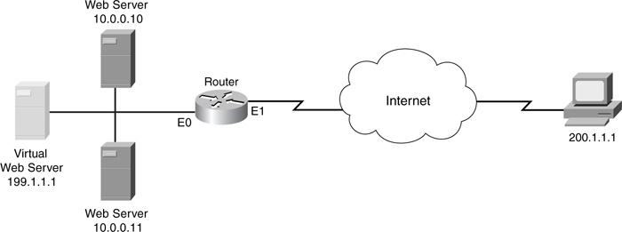
The standard ACL can be either named or numbered. The ACL references the destination IP address (or addresses) that external users are using to access your internal resource: This is the address that your DNS server is sending in DNS replies to the external users. Figure 11-9 shows a simple example, using a virtual IP address (199.1.1.1) to associate with the internal web servers (10.0.0.10 and 10.0.0.11). Using a virtual IP address is a common practice. You need to use this virtual address in your DNS server’s resolution record.
The ip nat inside destination list command binds together the ACL and pool name: It tells the Cisco IOS that when traffic is sent to the address or addresses listed in the standard ACL, these destination addresses should be changed to those in the NAT pool, using a round-robin scheme.
Step 3, specifies which of your interfaces are internal and external. This is done with the ip nat inside and ip nat outside interface commands.
Using Figure 11-9, take a look at an example of configuring traffic distribution. In Example 11-8, 199.1.1.1 is the virtual server IP address; this is the IP address that your DNS server is sending to external users.
Example 11-8 Basic Traffic Distribution Configuration
Router(config)# ip nat pool inside-hosts 10.0.0.10 10.0.0.11
prefix-length 24 type rotary
Router(config)# access-list 1 permit 199.1.1.1
Router(config)# ip nat inside destination list 1 pool inside-hosts
Router(config)# interface ethernet0
Router(config-if)# ip nat inside
Router(config-if)# exit
Router(config)# interface ethernet1
Router(config-if)# ip nat outside
In Example 11-8, the ip nat pool command specifies the two internal servers that will be handling traffic directed to 192.1.1.1. Notice that the type rotary parameter specifies that traffic distribution is used. The access-list statement specifies the address that external users are using when trying to access the internal web servers: 192.1.1.1. The ip nat inside destination command binds together the NAT pool and ACL: When outside users send traffic to 192.1.1.1, it is translated to the addresses in the NAT pool. In this example, the first external connection request will be redirected to 10.0.0.1, the second to 10.0.0.2, the third to 10.0.0.1, and so on. Below this, the location of NAT is specified on the interfaces with the ip nat {inside | outside} interface command.
Caution
When using this method of traffic distribution with the Cisco IOS, you should be forewarned that the Cisco IOS cannot detect whether one of the servers in the NAT pool has failed, nor can it detect the load on the respective servers. For example, if 10.0.0.10 failed in Figure 11-9, the Cisco IOS still would use this address in load balancing. Therefore, I recommend using this solution only in a very simple setup. Chapter 12 introduces a better solution to this problem.
Configuration of Translation Limits
When the Cisco IOS performs address translation, it stores its translation information in a translation table. These records are kept for a period of time before they are removed. This allows older entries to be aged out, to allow new connections. This is done primarily to age out older idle connections. You can specify two types of limits: the total number of connections and the timeout for connections. The following two sections discuss their configuration.
Setting Connection Limits
By default, there is no preconfigured limit to the number of entries that the Cisco IOS will store in its address translation table. You can specify a limit with the following command:
Router(config)# ip nat translation max-entries #_of_entries
The number of entries can range from 1 to 2,147,483,647. If you have hard-coded a limit and want to remove the limit (set it back to the factory default), just preface the previous command with the no parameter. Unless you are having memory issues on your router, you probably will leave this setting alone.
Setting Timeout Limits
Dynamic address-translation entries time out after their idle period expires. The Cisco IOS actually uses many different timeouts, based on the connection type, to time out idle connections. Here is the command to configure them:
Router(config)# ip nat translation timeout_parameter {seconds | never}
The timeout parameters, including their default timeout values, are listed in Table 11-4. The timeout value is specified either in a numerical seconds value or in the never parameter; the never parameter keeps an entry in the translation table until the router is rebooted.

Verifying and Troubleshooting Address Translation
When you have configured address translation on your router, you can use various show, clear, and debug commands to assist you in verifying and troubleshooting address translation. The following three sections cover these commands.
show Commands
To view your address-translation table, which displays static and dynamic entries, use the show ip nat translations command:
Router# show ip nat translations [esp] [icmp] [pptp] [tcp] [udp]
[verbose] [vrf vrf_name]
Without any options to the show ip nat translations command, all entries in the table are displayed. Table 11-5 explains the options for this command.

Take a look at a few examples of the use of this command. Example 11-9 shows an example of using the show ip nat translations command.
Example 11-9 Using the show ip nat translations Command
Router# show ip nat translations
Pro Inside global Inside local Outside local Outside global
--- 199.1.1.1 10.0.0.1 --- ---
--- 199.1.1.1 10.0.0.2 --- ---
Notice that Example 11-9 does not contain any port numbers, which shows that the Cisco IOS is performing NAT. If the Cisco IOS was performing PAT, the display would look like Example 11-10.
Example 11-10 Using the show ip nat translations Command to Display PAT Connections
Router# show ip nat translations
Pro Inside global Inside local Outside local Outside global
tcp 199.1.1.1:33348 10.0.0.1:33348 200.1.1.1:23 200.1.1.1:23
tcp 199.1.1.1:33348 10.0.0.2:33349 200.1.1.1:23 200.1.1.1:23
Example 11-11 shows sample output when you use the verbose parameter.
Example 11-11 Using the verbose Parameter in the show ip nat translations Command
Router# show ip nat translations verbose
Pro Inside global Inside local Outside local Outside global
tcp 199.1.1.1:2688 10.0.0.20:2688 200.1.1.1:23 200.1.1.1:23
create 00:00:16, use 00:00:14, left 23:59:45, Map-Id(In): 1, flags:
extended, use_count: 0, entry-id: 3, lc_entries: 0
In Example 11-11, only one PAT entry is listed—from an internal device (10.0.0.20 → 199.1.1.1), which created a Telnet to 200.1.1.1. This entry was created 16 seconds ago and has been in use for 14 seconds.
To view statistics regarding the use of address translation, use the following command:
Router# show ip nat statistics
Example 11-12 shows the output of this command.
Example 11-12 Using the show ip nat statistics Command
Router# show ip nat statistics
Total active translations: 1 (0 static, 1 dynamic; 1 extended) (1)
Outside interfaces: (2)
Ethernet1
Inside interfaces:
Ethernet0
Hits: 121 Misses: 4 (3)
Expired translations: 3 (4)
Dynamic mappings: (5)
-- Inside Source
[Id: 1] access-list 1 pool dynamic-nat-pool refcount 1
pool dynamic-nat-pool: netmask 255.255.255.0
start 192.1.1.1 end 192.1.1.1
type generic, total addresses 1, allocated 1 (100%), misses 0
Refer to the numbers on the right side of Example 11-12 for the following explanation of the output. In Example 11-12, Statement 1 shows the total number of active translations. In this example, there are no static translations, one dynamic translation, and one extended translation. An extended translation is one that uses port numbers, as PAT does.
Statement 2 shows which interfaces are associated with the inside and outside of the network. In Statement 3, “Hits,” refers to the number of times the Cisco IOS looked in the address-translation table and found a matching entry; “Misses” refers to the number of times that the Cisco IOS did not find a matching entry in the translation table and had to create one. Statement 4 refers to the number of entries that were removed from the translation table because they expired (the corresponding idle timer elapsed).
Statement 5 refers to the address-translation policies that are configured on the router. The access-list 1 pool dynamic-nat-pool reference indicates that there has been one match on the ACL, resulting in an address translation. Below this is the address pool used. In this instance, only a single address is listed: 192.1.1.1. The “allocated” reference indicates that one address is being used from the pool and that no misses occur when looking up a reference in the address translation table.
clear Commands
You can remove a dynamically learned entry from the address-translation table using the clear ip nat translation command:
Router# clear ip nat translation *
Router# clear ip nat translation inside | outside
global_IP_address local_IP_address
Router# clear ip nat translation protocol inside | outside
global_IP_address global_port
local_IP_address local_port
The first command removes all dynamic entries from the address-translation table. The second removes either inside or outside entries with the matching global and local address. The third command enables you to remove a specific entry, based on the protocol and port number.
Note
The clear command cannot remove static entries from the address-translation table. To remove a static entry, you need to preface the respective static NAT configuration mode command with the no parameter.
Any time you make changes in your address-translation policies, I highly recommend that you clear the address-translation table on your router. This forces the router to use the new policies immediately. Actually, I recommend that you clear the address-translation table when you make changes to any policy on the router, including address translation, ACL, CBAC, and other features that implement policies. If you have worked on a Cisco PIX before, you should be familiar with this task.
debug ip nat Command
For troubleshooting, the Cisco IOS supports a debug command to examine low-level details. Here is the syntax of this command:
Router# debug ip nat [standard_ACL_#] [detailed] [h323] [ipsec]
[port] [pptp] [route] [sip] [skinny] [vrf]
You can qualify the debug ip nat command by giving the command a parameter, which then restricts the amount of debug output that the Cisco IOS displays.
Example 11-13 shows the use of this command.
Example 11-13 Using the debug ip nat detailed Command
Router# debug ip nat detailed
IP NAT detailed debugging is on
Sep 17 16:30:04.438: NAT*: i: icmp (10.0.0.21, 512) -> (1)
(200.1.1.1, 512) [25201]
Sep 17 16:30:04.438: NAT*: s=10.0.0.21->192.1.1.1, (2)
d=192.168.2.2 [25201]
Sep 17 16:30:04.442: NAT*: o: icmp (200.1.1.1, 512) -> (3)
(192.1.1.1, 512) [25201]
Sep 17 16:30:04.442: NAT*: s=200.1.1.1, d=192.1.1.1-> (4)
10.0.0.21 [25201]
Refer to the numbers on the right side of Example 11-13 for the following explanation of the output. In Statement 1 of this example, an ICMP packet (i) from 10.0.0.21 is being sent to 200.1.1.1 (the router notices that address translation must be performed on this connection, which can be seen based on the NAT* indication). In Statement 2, the Cisco IOS translates the source address from 10.0.0.21 to 192.1.1.1. In Statement 3, an ICMP response is received from the destination (200.1.1.1), and the router notices that it must perform address translation on this packet. Statement 4 shows the address translation occurring, changing the destination address of 192.1.1.1 to 10.0.0.21.
Tip
I cannot begin to stress how useful the debug ip nat command is. I have used it numerous times to troubleshoot address translation issues, especially ones with complex filtering configurations. However, this command is CPU intensive and should be disabled immediately after you have found and fixed your problem.
NAT and CBAC Example
Now that you have a basic understanding of NAT, let us talk about how you would use CBAC—or, for that matter, any type of filtering on a router that also has NAT configured on it. In Figure 11-10, the network is using a private address space (192.168.1.0/24), and the ISP has assigned it a Class C public address space: 192.1.1.0/24. However, one restriction of the use of this address space is that two of these addresses must be used for the perimeter router’s Ethernet1 connection to the ISP router (192.1.1.1 and 192.1.1.2). Also, the internal network has three services that it wants to allow external users to access: a DNS server, a web server, and an e-mail server.

Note
To simplify matters, assume that the DNS server is using split DNS. With split DNS, the DNS server has two (or more) sets of resolution entries. Based on the source of the DNS query, the DNS server sends back a specific resolution. In this example, when internal devices request resolution for internal services, the DNS server sends back the appropriate private address (192.168.1.0/24) in the reply. However, when external devices request resolution for internal services, the DNS server sends back the corresponding public address for the service (the one configured through static NAT on the router). This is a common approach to dealing with the use of public and private addresses along with address translation.
In this example, assume that all unnecessary services have been disabled (this was covered in Chapter 4, “Disabling Unnecessary Services”). I use static NAT for the internal services and dynamic NAT for the internal users. Example 11-14 focuses primarily on the configuration for ACL filtering, CBAC, and NAT on the company router.
Example 11-14 Using ACLs, CBAC, and NAT on a Perimeter Router
Router(config)# ip route 0.0.0.0 0.0.0.0 192.1.1.1
Router(config)#
Router(config)# ip inspect name allow-back-in ftp (1)
Router(config)# ip inspect name allow-back-in http
Router(config)# ip inspect name allow-back-in realaudio
Router(config)# ip inspect name allow-back-in smtp
Router(config)# ip inspect name allow-back-in tcp
Router(config)# ip inspect name allow-back-in udp timeout 20
Router(config)# ip inspect name allow-back-in vdolive
Router(config)#
Router(config)# ip nat inside source static 192.168.1.2 192.1.1.12 (2)
Router(config)# ip nat inside source static 192.168.1.3 192.1.1.13
Router(config)# ip nat inside source static 192.168.1.4 192.1.1.14
Router(config)#
Router(config)# ip nat pool inside-nat 192.1.1.20 192.1.1.254 (3)
netmask 255.255.255.0
Router(config)# ip nat inside source list 1 pool inside-nat
Router(config)# access-list 1 permit 192.168.1.0 0.0.0.255
Router(config)#
Router(config)# access-list 100 deny (4)
Router(config)# ! <--list of boguns and others
should be placed here-->
Router(config)# access-list 100 permit icmp any 192.1.1.0 0.0.0.255
unreachable
Router(config)# access-list 100 permit icmp any 192.1.1.0 0.0.0.255
echo-reply
Router(config)# access-list 100 permit icmp any 192.1.1.0 0.0.0.255
packet-too-big
Router(config)# access-list 100 permit icmp any 192.1.1.0 0.0.0.255
time-exceeded
Router(config)# access-list 100 permit icmp any 192.1.1.0 0.0.0.255
administratively-prohibited
Router(config)# access-list 100 permit tcp any host 192.1.1.12 eq 25
Router(config)# access-list 100 permit tcp any host 192.1.1.13 eq 80
Router(config)# access-list 100 permit udp any host 192.1.1.14 eq 53
Router(config)# access-list 100 deny ip any any
Router(config)#
Router(config)# interface Ethernet0
Router(config-if)# ip address 192.168.1.1 255.255.255.0
Router(config-if)# ip nat inside
Router(config-if)# exit
Router(config)# interface Ethernet1
Router(config-if)# ip address 192.1.1.2 255.255.255.0
Router(config)# ip access-group 100 in
Router(config)# ip nat outside
Router(config)# ip inspect allow-back-in out (5)
Refer to the numbers on the right side of Example 11-14 for the following explanation of the configuration. In this example, Statement 1 sets up the inspection for CBAC and then is activated outbound on the external interface, ethernet1, in Statement 5. In Statement 2, three static NAT translations are set up for the e-mail, web, and DNS servers. In Statement 3, these three commands set up dynamic NAT for the inside users. Statement 4 filters ingress traffic from the Internet—I put in a placeholder (a comment with the !) for filtering bogun, private IP, and other addresses. Refer to Chapter 7, “Basic Access Lists,” for information on configuring these ACL entries. I then allow certain ICMP messages and traffic to the three internal servers. Everything else is denied. Note that the global addresses are used in the ACL statements, not the addresses that these servers actually have assigned on them. Also, notice that I have enabled NAT on the inside (ethernet0) and outside (ethernet1) interfaces.
As you can see from this example, setting up NAT with other Cisco IOS features is not that difficult. However, one important point to make about this example is that, when you set up filters, you always should use the addresses that show up in the packet headers. For example, notice that in the ingress filter on ethernet1, I specified the destination addresses as the public addresses; this is because the Cisco IOS processes the ACL before it performs NAT:
• For the outside interface, filter on the global addresses.
• For the inside interface, filter on the local addresses.
Also notice that you can use unused addresses off a router’s interface for your address translation. In this example, I used unused addresses from 192.1.1.0/24, which is connected to ethernet1. In this instance, the router answers all ARP requests to 192.1.1.0/24 addresses that it has in its address-translation table, basically spoofing or proxying the responses. In this situation, make sure that you do not disable proxy ARP on the router’s external (E1) interface.
Summary
This chapter showed you the basics of address translation: its components, how it works, and how to configure it. Many uses of address translation, and many different types, exist. In the most common case, address translation is used to translate private addresses to public addresses as traffic leaves a network, destined for a public network, such as the Internet. Normally, dynamic NAT and PAT are used to handle outbound connections; static NAT and PAR are used to handle inbound connections. As with any solution, address translation provides benefits and has limitations.
Next up is Chapter 12, which shows you some of the issues with address translation and how the Cisco IOS can deal with these issues.