
Chapter 14. Authentication Proxy
The last chapter discussed how you can use lock-and-key to authenticate users before allowing them access through your perimeter router. As you recall, lock-and-key requires a user first to Telnet into the router to authenticate. Then the Telnet is terminated by the router, and a dynamic ACL entry is created for the user to allow traffic through the router. Lock-and-key is a nifty feature, but it does have limitations:
• It was developed primarily for dialup use, with only one user accessing the router’s interface.
• The extended ACL applied to the interface can have only one dynamic entry, which all users must share; this makes it almost impossible to enforce per-user restrictions.
• It requires you to Telnet into the router first, requiring a user’s knowledge of the authentication process that must take place first before the user can access resources specified in the dynamic ACL entry.
To overcome these deficiencies, Cisco developed authentication proxy (AP). AP is basically lock-and-key on steroids. It provides the same basic functions as lock-and-key, but it also includes many enhancements that make it more flexible and scalable. Actually, AP and the Cisco PIX’s cut-through proxy (CTP) are very similar in function. This chapter focuses on the use and configuration of this Cisco IOS Firewall feature.
Introduction to AP
AP is part of the Cisco IOS Firewall feature set and thus requires you to purchase the appropriate Cisco IOS software to access this feature. If you do not have the budget for the Cisco IOS Firewall feature set, you are limited to using lock-and-key for user authentication of connections traveling through the router.
AP enables you to define per-user security access policies that are activated when a user authenticates to the router. For example, you might want to deny all kinds of inbound traffic into your network but open temporary holes in your perimeter router/firewall for specific users. Of course, in many instances, you might not know from what devices these users will be initiating their inbound connections.
AP can deal with this by having the Cisco IOS authenticate users and, based on their authentication, open temporary holes in your router’s ACL configuration to allow users to access allowed resources. Unlike with lock-and-key, you can control this access on a per-group or per-user basis. For example, you might have two sets of external users, programmers and network administrators, with two different access policies. When an external user authenticates, the appropriate ACL entries are added to the inbound ACL to allow the user to access the appropriate services. For the programmers, you might set up policies to allow them access to specific development machines; for the network administrators, you might set up access policies to allow them to access specific network-management devices, such as a bastion host.
AP Features
AP first was introduced in Cisco IOS version 12.0(5)T. However, it was limited to performing authentication by HTTP: The user had to use a Java-enabled web browser for authentication. Since then, Cisco has added support for other methods of authentication. These authentication methods are supported:
• HTTP—Cisco IOS 12.0(5)T
• HTTPS (using SSL)—Cisco IOS 12.2(11)YU and 12.2(15)T (you need a Cisco IOS crypto k8 or k9 image to support encryption with HTTPS)
• Telnet—Cisco IOS 12.3(1)
• FTP—Cisco IOS 12.3(1)
As you can see from this list, AP is more flexible than lock-and-key: Lock-and-key supports only Telnet.
AP also supports a form of downloadable ACLs called access profiles. AP requires you to use an external AAA server that has the users’ accounts and access profiles configured on it. When a user successfully authenticates, the user’s access profile is downloaded to the router, where the Cisco IOS includes the access profile as temporary ACL entries in the router’s static ACL. Cisco’s Cisco Secure ACS product supports access profiles with AP.
AP is compatible with many other Cisco IOS security features, including IDS, CBAC, NAT, and IPSec and VPNs. For example, AP keeps track of incoming HTTP requests to determine whether authentication is needed. If AP sees an abnormally high number of open HTTP requests, this can indicate that the router is under a DoS attack. AP can limit the number of these open requests and drop any requests that go above this threshold.
AP even works with CBAC and NAT; however, if you want to use AP and have NAT configured on your router, Cisco requires you also to use CBAC. NAT can be somewhat tricky with AP. For example, a user might use AP to authenticate using its original address, but NAT then translates this address to another. The concern here is that any temporary dynamic ACL entries created because of the AP authentication should have the correct addressing information. CBAC is needed here because CBAC inspects traffic to make sure that the correct ACL entries are created for the authenticated user.
AP is integrated into AAA, as briefly mentioned in Chapter 5, “Authentication, Authorization, and Accounting.” One nice feature of AP and AAA is that you can generate start and stop accounting records for the traffic originating from the authenticated user (this requires the configuration of RADIUS attributes 42, 46, and 47 for both RADIUS and TACACS+ server connections).
Table 14-1 summarizes the features of AP by comparing AP with lock-and-key.
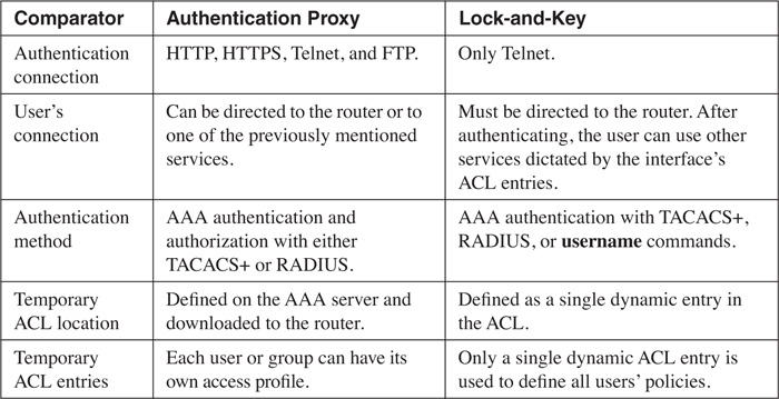
Tip
Cisco recommends that you use lock-and-key if you do not have an AAA server or the Cisco IOS Firewall feature set. I highly recommend that if you need to authenticate users before allowing them through your perimeter router/firewall, you purchase the Cisco IOS Firewall feature set as well as Cisco Secure ACS. This solution provides a more secure and scalable solution than lock-and-key. I commonly refer to lock-and-key as the “poor man’s” version of AP.
AP Process
Now that you understand some of the features of AP, this section examines the process that AP uses to authenticate a user and open temporary holes in your ACL.
As you will see later in this chapter, configuring AP is more complex than configuring lock-and-key. One of the things you need to decide is what authentication method or methods are needed: HTTP, HTTPS, Telnet, and/or FTP. My personal recommendation is HTTPS because the connection is encrypted. However, if you are using one-time passwords (OTP), described in Chapter 3, “Accessing a Router,” any of these authentication methods is fine.
AP Process Example
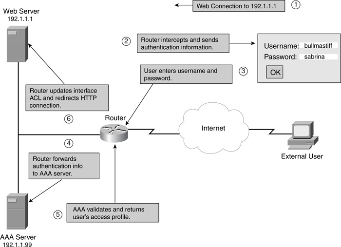
Figure 14-1 illustrates the process that takes place with AP. This example assumes that HTTP is used to perform the authentication by the router. As you can see in Figure 14-1, this process is similar to what lock-and-key does during the authentication process, although some differences exist. In this example, the user can cause authentication to occur in one of two methods:
• Open a web connection to the router itself
• Open a web connection to an internal web server
One main difference exists between lock-and-key and AP: AP allows the router to intercept the user’s connection (only HTTP, HTTPS, Telnet, and FTP) and perform authentication; after authentication, it allows the router to redirect the user’s connection to the resource.
The following is an explanation of the numbered steps in the example shown in Figure 14-1:
Step 1 In this example, the user opens a web connection (HTTP) to the internal web server (192.1.1.1).
Step 2 The router has AP configured, with HTTP as the authentication mechanism, and it intercepts the HTTP connection request. The router sends back a username and password prompt to the user. In the case of HTTP or HTTPS, this is a window that pops up with two text boxes for the username and password.
It is important to point out that if your user has software that blocks pop-ups, this window is not displayed. Therefore, care must be taken to ensure that this window appears on the user’s screen.
Step 3 The user must enter a username and password for the appropriate prompts. For HTTP or HTTPS authentication, the user must click the OK button to send the information to the router.
For FTP, if the router is performing redirection and the AAA user account and the FTP server use different usernames and passwords, you can specify both in the username and password prompts. The router then uses the appropriate username/password combination for AAA and for the redirection to the FTP server. When entering the usernames, the user should enter them as AAA_username@FTP_username, where the AAA and FTP usernames are separated by the @ symbol. The passwords use the same nomenclature: AAA_password@FTP_password.
If you are using one-time passwords, such as token cards, a user can enter the username/password combination up to three times. After this, the user must enter two valid token passwords in succession before the AAA server allows authentication.
Step 4 When the router receives the user’s authentication information, it forwards this through TACACS+ or RADIUS to the AAA server.
Step 5 The AAA server authenticates the user. If the user successfully is authenticated, the AAA server sends the user’s access profile to the router. The access profile is basically a simplified grouping of ACL statements that define what the user is allowed access to.
Step 6 If the user successfully authenticates, the user receives a pop-up window indicating success (just click the OK button to close it). The router converts the access profile into actual temporary ACL entries that then are activated inbound on the appropriate interface. In this example, this would be inbound on the external interface. The dynamic ACL entries allow the user to access the approved resources. The router actually customizes the user’s access profile by placing the user’s source IP address in the source field of the ACL entry or entries.
If the router intercepted the HTTP connection, the router redirects the initial connection request to the internal web server.
If the user is not successful in authenticating, the router resends the prompts to the user so that the user can attempt to authenticate again. If the user fails to authenticate after five attempts, the router blocks all new authentication attempts from the user for 2 minutes. This is done to prevent DoS attacks.
One nice feature about this process is that AP enables the router to intercept supported connections, perform authentication, and, for successful authentications, redirect the initial connection request to the appropriate resource.
Of course, the process just described assumes that this is the first time the user initiates a connection. After authentication, the router caches the user’s information from the AAA security server and uses this information to determine whether subsequent connections need to be authenticated. The router keeps the cached information for a user as long as traffic is coming to and from the user. If the user is idle for a specified period of time, AP removes the temporary ACL entries and cached information and forces the user to reauthenticate when the user initiates new traffic.
AP Authentication and JavaScript
To provide for secure authentication, AP uses JavaScript. This ensures that the user’s username and password are sent to the router instead of accidentally being sent to another web server. Therefore, Cisco highly recommends that JavaScript be enabled for HTTP/HTTPS AP connections on your users’ desktops.
However, AP does support authentication without JavaScript, especially in sites that have disabled Java because of security reasons. If JavaScript is disabled, when the user attempts the web connection and the router intercepts it, a pop-up window is opened on the user’s desktop that contains the following:
• Instructions on how to enable JavaScript to perform the authentication process automatically
• Instructions on how to manually complete the authentication process and establish the user’s web connection
To perform the authentication process manually, follow these steps:
Step 1 Close the pop-up window. Do not click the Done button; instead, click File > Close from the main menu. It is important that you use this process; otherwise, manual authentication will fail.
Step 2 From the user’s original web browser window, the user should click the Refresh or Reload button.
If the user’s last authentication attempt succeeded, the web page that the user initially was trying to access is displayed. Otherwise, the username/password pop-up window is redisplayed and the user must authenticate again.
Caution
Because of the process used with manual authentication, I highly recommend that you explain to your users the process that needs to be done to complete the authentication process successfully. If the user clicks the Done button from the JavaScript warning window, the authentication process will not complete correctly.
AP Usage
AP can be used in many different situations to provide a more secure access method. The following two sections describe when you might want to use AP and where AP typically is deployed.
When to Use AP
AP actually has many practical uses. AP proves useful to your security arrangements in these situations:
• You need to authenticate and authorize external users before allowing them to access specific internal resources, such as a private web server.
• You need to authenticate and authorize internal users before allowing them to access extranet or Internet resources.
• You want to enhance your VPN setup by preauthenticating users before allowing them to set up a VPN connection to your router.
• You need to set up different levels of access on a per-user basis, but you do not necessarily know the IP addresses of the users because these can change on a day-by-day basis (probably because they use PPP or DHCP to acquire their addressing information).
• You need a detailed audit of who connects through the router, how long they were connected, and when these connections occurred.
Where to Use AP
As you saw in the last section, you can use AP to authenticate and authorize access for external users accessing internal resources, as well as internal users accessing external resources. You can configure both of these policies simultaneously on your router.
Figure 14-2 illustrates these policies. In this example, two AP policies have been defined:
• Internal—All users must be authenticated before accessing the Internet. Salespeople have complete access, but accounting people are allowed access only to port 80 and ports 8080 through 8099.
• External—Any external user who wants to access the internal private web server first must be authenticated.
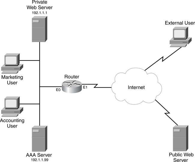
In this example, you create two AP policies: one applied inbound on the internal interface (e0) for the internal users, and one applied inbound on the external interface (e1) for the external users.
Limitations of AP
Despite its advantages, AP has limitations. As with lock-and-key, AP is susceptible to spoofing. After authentication, the router inspects subsequent traffic from the user by examining the user’s source IP address. Therefore, if a hacker knows that a user successfully has authenticated, the hacker can compromise the router by executing some form of spoofing attack, taking advantage of this knowledge (and weakness within the mechanics of AP).
Other limitations of AP include these:
• AP works only for traffic traveling through, not to, the router.
• Authentication must occur with HTTP, HTTPS, Telnet, or FTP. These are the most commonly used protocols that provide a mechanism for bidirectional communication, which is why you see only these four methods for authentication on the router. However, after being authenticated, based on any downloaded ACLs, the user can access other resources in the network.
• With HTTP, the Cisco IOS examines only port 80 connections.
• Load balancing with multiple AAA servers is not supported currently with AP.
• If two users are sharing the same device, AP authenticates only the first user, not the second, because AP examines the source IP address in packets to determine whether authentication has been performed.
• As mentioned in the “AP Authentication and JavaScript” section, you can perform authentication without JavaScript, but it is not recommended because it is not as secure.
AP Configuration
The next part of this chapter deals with configuring AP on your Cisco router. Before continuing with the configuration, though, you should meet some prerequisites:
• AP uses AAA to perform authentication and authorization. Make sure that you understand the operation and configuration of AAA discussed in Chapter 5.
• It is highly recommended that you use CBAC (see Chapter 9, “Context-Based Access Control”) and ACLs (see Part III, “Nonstateful Filtering Technologies”) to complement AP.
• With HTTP and HTTPS authentication, Cisco recommends that you use either Microsoft’s Internet Explorer 3.0 or later, or Netscape’s Navigator 3.0 or later. Other web browsers might or might not work, so you are on your own if you experience problems with other vendors’ web browser products.
When you have met the prerequisites, you are ready to proceed to configuring AP. The following sections discuss the different components that you need to configure:
• Configuring AAA on your router
• Configuring AAA on your AAA server
• Preparing for HTTP and HTTPS (FTP and Telnet do not require special configurations for AP)
• Configuring AP policies
• Tuning AP
• Protecting against access attacks
Configuring AAA on Your Router
One of the first steps is to set up AAA on your router. AAA was covered in Chapter 5, so I do not spend that much time discussing its configuration here. However, one important point to make about AAA and AP is that you must use a TACACS+ or RADIUS server. AP does not support any method of local authentication or authorization.
You will use the following basic AAA commands:
Router(config)# aaa new-model (1)
Router(config)# tacacs-server host IP_address (2)
[single-connection] [port port_#] [timeout seconds]
[key encryption_key]
Router(config)# radius-server host IP_address
[auth-port port_#] [acct-port port_#] [timeout seconds]
[retransmit retries]
[key key_value]
[alias {hostname | IP_address}]
Router(config)# aaa authentication login default (3)
{group radius | group tacacs+ | group server_group}
Router(config)# aaa authorization auth-proxy default (4)
{group radius | group tacacs+ | group server_group}
Router(config)# aaa accounting auth-proxy default start-stop (5)
{group radius | group tacacs+ | group server_group}
Here is a brief explanation of these commands, with reference to the numbering on the right side of the syntax:
1. This command enables AAA.
2. This statement and the next one specify your AAA servers. Remember that you can group your servers with the aaa group server command.
3. This command enables AAA authentication.
4. This command enables authorization for AP.
5. This command, which is optional, sets up AAA accounting for AP.
Note
If you are setting up AP to verify access from internal users to the outside world and have an ACL applied inbound on the internal interface, you need to allow either RADIUS or TACACS+ communications to the router. RADIUS uses UDP ports 1645 (authentication and authorization) and 1646 (accounting), as well as UDP 1812 and 1813. TACACS+ uses TCP port 49.
Configuring AAA on Your Server
When you have configured AAA on your router, you need to set up AAA on your security server. AP supports the following AAA security servers:
• Cisco Secure ACS 2.1.x and later for Windows NT/2000
• Cisco Secure ACS 2.3 for UNIX
• The Ascend RADIUS server
• The Livingston RADIUS server
You need to do a few things on your AAA server:
• Add your users and groups.
• Enable the AP service.
• Create downloadable user profiles that the Cisco IOS converts to ACLs.
The following two sections cover the last two points.
Note
The setup of AP on an AAA server is not a simple process, so I briefly discuss it in this chapter. Note, however, that I cover only the use of Cisco Secure ACS for NT/2000 when setting up AP. The version of ACS that I am using is Cisco Secure ACS 3.2. Configuration of other ACS versions and other AAA servers is beyond the scope of this book.
AP Service
By default, the AP service on the Cisco ACS product is disabled. The first thing you need to do is enable it. Enabling it is a two-step process: You need to make changes to the Interface Configuration and Network Configuration sections.
To perform the necessary configuration for the Interface Configuration section, follow these steps:
Step 1 Click the Interface Configuration button in the left-side vertical toolbar.
Step 2 Click the TACACS+ (Cisco IOS) hyperlink in the middle section of the web page.
Step 3 Scroll down to the TACACS+ Services section.
Step 4 In the New Services section, click the closest empty check box and, under the Service column, enter auth-proxy.
Step 5 Click the Submit button at the bottom of the window to accept your changes.
In the Network Configuration section, make sure that your router is listed and that the AAA server and router can communicate with each other.
User Authorization Profiles
After you have enabled AP, you need to activate it in the group or groups that your users are associated with that will be using AP. To do this, follow these steps in ACS:
Step 1 Click the Group Setup button in the left-side vertical toolbar.
Step 2 Select the group that you want to add AP to, and click the Edit Settings button.
Step 3 Scroll down to the TACACS+ Settings text box.
Step 4 Toward the bottom of this box, you will find the AP service you just added.
Step 5 Click the check box to the left of the auth-proxy service name.
Step 6 Click the check box to the left of the Custom Attributes description.
Step 7 Beneath the Custom Attributes description is a large text box where you can configure your user authorization profile (UAP) statements. I describe this configuration later.
Step 8 After you have entered your custom attributes, at the bottom of the screen, click the Submit+Restart button.
The UAP in the custom attributes defines what resources a user is authorized to access after being authenticated. Two types of statements exist in a UAP:
priv-lvl=15
proxyacl#number=permit protocol any destination_address destination_mask
protocol_information
The priv-lvl command assigns the privilege level to the authenticated user. For AP, this must be 15. The proxyacl# commands define the UAP—what the user can access after being authenticated. These are basically a simplified access-control entry, which, when the AAA server sends this to the Cisco IOS, the Cisco IOS converts into an ACL statement. Following the proxyacl# portion of the command is a statement number. The first statement is numbered 1, the second is 2, and so on. These are used to order your statements. This is followed by an equals sign (=) and then the ACL statement. Note that the format of the ACL statement is the same as that used by entries in a named extended ACL.
Note
Make sure that you use the keyword any for the source address. When the router receives the UAP entries, the Cisco IOS changes this keyword to the actual source address used by the authenticated user.
Here is a simple UAP example used for the external users in Figure 14-2 trying to access the private web server:
priv-lvl=15
proxyacl#1=permit tcp any 192.1.1.1 eq 80
This is a straightforward configuration. Note that you can configure multiple proxyacl# commands; just make sure that each entry has a unique command number.
Preparing for HTTP or HTTPS
After you have configured AAA on the server and the router, you need to take some preparatory steps on your router to allow AP to occur. As you recall, the Cisco IOS supports HTTP, HTTPS, FTP, and Telnet for authentication and authorization. This means that you need to allow these services in your ACL configuration. For example, if you are setting up AP that uses only HTTPS, and if HTTPS must be done to the router first, you need an entry in the router’s inbound ACL that allows the HTTPS (TCP port 443) connection to the router (the destination IP address in the ACL entry should be an address on the router). If you are using other services, you also need to allow these in your ACL entries. Plus, if you are using redirection with HTTP or HTTPS, you need to allow the HTTP/HTTPS connection to the destination service in your ACL entry.
HTTP Configuration Tasks
For HTTP, you need to enable and set up the router’s HTTP server. You need to configure these commands on your router:
Router(config)# ip http server
Router(config)# ip http authentication aaa
Router(config)# ip http access-class standard_ACL_#
The first two commands are necessary. The first command, ip http server, enables the router’s HTTP server function. The ip http authentication aaa command allows the Cisco IOS to use AAA for authentication. The third command is optional: The ip http access-class command can be used to restrict certain source addresses to access the router’s HTTP server function. This is useful if you will be using AP only to authenticate internal users accessing external resources. In this instance, you know the addresses that the internal clients use. However, for external users, you probably do not know the source addresses, so this command would not be appropriate.
Configuration Tasks for HTTPS
HTTPS was introduced in Cisco IOS 12.2(11)YU and 12.2(15)T. The main advantage that HTTPS has over HTTP, FTP, and Telnet is that information shared across the connection, such as the username and password, is encrypted.
To set up HTTPS for AP, perform the following:
Step 1 Disable the HTTP server:
Router(config)# no ip http server
Step 2 Enable the HTTPS server function:
Router(config)# ip http server-secure
Step 3 Enable AAA for the HTTPS server:
Router(config)# ip http authentication aaa
Step 4 Define a Certificate Authority (CA) trustpoint (optional):
Router(config)# ip http secure-trustpoint CA_name
In this configuration, the only command that is new is step 4. When two devices are trying to establish a connection, a CA can provide proof of the identities of the two parties, thereby defeating man-in-the-middle or spoofing attacks. Identity information is stored in a certificate, defined in the X.509v3 standard. CAs commonly are used in VPNs as well as secure web transactions. I thoroughly cover the configuration of CAs in Chapter 19, “IPSec Site-to-Site Connections”; refer to this chapter for the router’s configuration for a CA.
Caution
Note that you do not need to configure a CA to have the router use certificates to verify a device’s identity. Instead, you can use HTTPS and have the router generate its own, self-signed certificate. The problem with this approach is that clients can do the same thing. Therefore, if you are very concerned about security, I highly recommend that you set up a CA and have both your router and users use certificates that are used by your own company’s CA or a public CA, such as Verisign. With this approach, you can be sure that when a device makes a connection, you can prove the other device’s identity.
Configuring AP Policies
After setting up AAA, and, if necessary, preparing the Cisco IOS for HTTP or HTTPS connections, you are ready to define your AP polices and tune AP parameters. To set and activate your AP polices, you need to perform two steps, similar to the steps that you perform when setting up CBAC:
• Define your AP policies.
• Activate your AP policies.
AP Policy Definitions
To define your AP policies, use the following configuration:
Router(config)# ip auth-proxy name AP_name {http | ftp | telnet}
[inactivity-timer minutes] [absolute-timer minutes] [list {ACL_# | ACL_name}]
The ip auth-proxy name command is used to create your AP policies. If you have more than one interface and you need to define different policies for these interfaces, each policy will have a different AP_name. The name is used to group your policy statements.
Following the name is the authentication method that you want your users to use. For HTTPS, use http. If you want to use more than one method, list each method in a separate ip auth-proxy name command, but use the same AP_name.
Two optional parameters follow. The inactivity-timer parameter specifies the number of idle minutes that the user’s authentication entries are kept before the Cisco IOS expires them. When they expire, the Cisco IOS removes the entries, which includes any temporary ACL entries that were downloaded from the AAA server. The absolute-timer parameter specifies that when the configured time period is reached, whether the user’s connection(s) are idle or not, the user’s authentication entries are expired and removed. By default, this value is set to 0, which means that only idle connections can be expired. These two timing parameters are used to override the global timing settings for AP (I discuss this command shortly).
Caution
When setting the time periods for AP connections, make sure that the time periods are higher than the time periods used by CBAC to expire connections. If the AP timer is smaller, problems can result: AP removes the connections, but CBAC thinks that they are still there, causing the connections to hang. You alleviate this problem by having CBAC remove the entries when the idle time period is reached.
One last optional parameter to this command is the specification of an ACL name or list. This can be a standard or extended ACL. For packets that match permit statements in the list, the router performs AP, ensuring that the user is authenticated. This enables you to control which users are authenticated.
Example 14-1 is a simple configuration example, based on the network shown in Figure 14-2, of defining your AP policies. Assume that HTTP is used here for authentication.
Example 14-1 Simple AP Policy Configuration
Router(config)# ip auth-proxy name internal_users http
Router(config)# ip auth-proxy name external_users http access-list 100
Router(config)# access-list 100 permit tcp any host 192.1.1.1 eq 80
As you can see in this example, two policies were defined: one for the internal users and one for the external users. For internal users, all users will be authenticated through HTTP, whereas, only external users trying to access web services on 192.1.1.1 will be authenticated.
AP Policy Activation
When you have created your AP policies, they are not used until activated on your router’s interface(s). This is accomplished with the following configuration:
Router(config)# interface type [slot_#/]port_#
Router(config-if)# ip auth-proxy AP_name
The ip auth-proxy command activates the specified AP policy on your router’s interface. For example, if you have defined two policies, one for internal users and one for external users, you need to activate the internal policy on all of the internal interfaces, and activate the external policy on all of the external interfaces.
In the previous example, to activate the two AP policies for Figure 14-2, you would use the configuration in Example 14-2.
Router(config)# interface ethernet0
Router(config-if)# ip auth-proxy internal_users
Router(config)# interface ethernet1
Router(config-if)# ip auth-proxy external_users
Tuning AP
You globally can change two basic items to tune AP for your router: an authentication banner, and idle and absolute timeouts. The authentication banner is displayed during the login process and is similar to the banner created with the banner motd command. However, this banner is used only by users being authenticated through AP. Here is the syntax for this command:
Router(config)# ip auth-proxy auth-proxy-banner {http | ftp | telnet}
[stop_character message stop_character]
As you can see, the format of this command is similar to that of the banner motd command: At the end, you need to specify a stop character at the beginning and ending of your banner message. Notice, however, that this is optional. If you omit the actual banner message, the router’s default login banner is used; otherwise, the banner that you specify here is used. With AP, you must specify the authentication type—http, ftp, or telnet—for the banner. Unfortunately, currently there is no method of defining a different banner for different policies. In other words, it is not possible with the current versions of the Cisco IOS to create one banner for internal users and a second banner for external users.
Note
If you do not configure an AP banner, no banner is displayed during the AP login process; the user is prompted only for the username and password.
Example 14-3 displays a simple sample of the use of this command.
Example 14-3 Creating a Banner for AP
Router(config)# ip auth-proxy auth-proxy-banner http #
***Unauthorized use of this system or the network***
*** is prohibited and will be punished to the***
*** fullest extent of the law ***
***To gain access, you must be an authorized user***
*** and must authenticate with an approved ***
*** username and password ***
#
Router(config)#
As you can see, you can enter a multiline banner.
As I mentioned with the ip auth-proxy name command previously, you can configure two timeouts for users’ connections: idle and absolute. Changing these values with the ip auth-proxy name command affects only the timeouts for users authenticated with the specific policy name. You globally can set these timeouts with the following two commands:
Router(config)# ip auth-proxy inactivity-timer minutes
Router(config)# ip auth-proxy absolute-timer minutes
The inactivity-timer parameter specifies the number of minutes after a user is idle that the Cisco IOS will remove the user’s authentication information, including any dynamic ACL entries that were created from the user’s profile downloaded from the AAA server. This number can range from 1 to 2,147,483,647; the default is 60 minutes.
The absolute-timer parameter specifies the number of total minutes that the user’s information is kept (it does not matter whether the user’s connections are idle). This value defaults to 0, which means that the timer is disabled.
Remember my caution in the “AP Policy Definitions” section: Make sure that these timer values are greater than those that CBAC uses. Also, if a user’s information is expired and removed, the user must reauthenticate before reaccessing previously authorized resources.
By default, even if you enable AAA accounting for AP, AP will not generate accounting records until you enable it with the following command:
Router(config)# ip auth-proxy auth-proxy-audit
When you do this and configure AAA accounting, the Cisco IOS creates start/stop records to record the users’ authentication activities.
Protecting Against Access Attacks
AP provides a limited solution to protect you against access attacks, called watch lists. Watch lists enable you to place blacklisted users on a list, which AP denies access for. The IOS dynamically can learn blacklisted users by examining failed access attempts, or this information can be configured statically.
By default, watch lists are disabled. To enable them, use the following command:
Router(config)# ip auth-proxy watch-list enable
When it is enabled, AP uses watch lists to block blacklisted users from any further authentication attempts. The Cisco IOS automatically blacklists a person if he tries to authenticate and fails five successive times. You can change this value with this command:
Router(config)# ip auth-proxy max-login-attempts maximum_login_#
The maximum number of logins can range from 1 to 2,147,483,647.
Note
The ip auth-proxy max-login-attempts command is actually independent of the watch list feature; it can be used with or without watch lists.
When a user exceeds the maximum number of allowed authentication attempts and watch lists are enabled, the user automatically is blacklisted. By default, a user is blacklisted for 30 minutes. After this time period, the user can attempt authentication again. To change this blocked period, use the following command:
Router(config)# ip auth-proxy watch-list expiry-time minutes
The expiration, or block, period can range from 1 to 2,147,483,647. When a user is blacklisted, after this expiration time passes, the user automatically is removed from the watch list.
You manually can add and remove devices from the watch list with the following two respective commands:
Router(config)# ip auth-proxy watch-list add-item host_IP_address
Router(config)# no ip auth-proxy watch-list add-item host_IP_address
Typically, you use the second command if a user accidentally enters the wrong username/password combination five or more times out of user/keyboard interface problems, and you need to remove that user from the watch list after instructing him what to enter to authenticate.
Verifying and Troubleshooting AP
After you have configured AP, you can use various show, clear, and debug commands to examine and troubleshoot your configuration. The following sections cover the use of these commands.
show Commands
These are the basic show commands that you use for AP:
• show [ip] access-list—Displays the router’s ACLs, including dynamic entries created by AP
• show ip auth-proxy configuration—Displays the AP configuration on the router
• show ip auth-proxy cache—Displays the status of users who are being authenticated or who have authenticated
• show ip auth-proxy watch-list—Displays information in the watch list
I look at the show ip access-list command first. Example 14-4 shows a sample of this command before a user has authenticated (this ACL is applied inbound on the external interface).
Example 14-4 An ACL Before AP Occurs
Router# show ip access-list
Extended IP access list 100
permit tcp any host 192.1.1.1 eq www
deny ip any any
In Example 14-4, only traffic to the internal web server (193.1.1.1) is allowed. This is required for AP to work. Example 14-5 shows simple output after a user successfully has authenticated.
Example 14-5 An ACL After AP Occurs
Router# show ip access-list
Extended IP access list 100
! Here are the dynamic ACL entries created from the
! user's authentication.
permit icmp host 200.1.1.1 192.1.1.0 0.0.0.255
permit tcp host 200.1.1.1 192.1.1.2 eq www
permit tcp any host 192.1.1.1 eq www (64 matches)
deny ip any any
As you can see in Example 14-5, two dynamic ACL entries were created for user 200.1.1.1.
To view your router’s AP configuration, use the show ip auth-proxy command, as shown in Example 14-6.
Example 14-6 Viewing Your Router’s AP Configuration
router# show ip auth-proxy configuration
Authentication global cache time is 60 minutes
Authentication global absolute time is 0 minutes
Authentication Proxy Rule Configuration
Auth-proxy name AP-rules
http list not specified auth-cache-timeout 60 minutes
In Example 14-6, only one policy was created: AP-rules. This policy did not specify an ACL and did not change the timers for the policy.
After you have configured AP, have a user initiate a connection that will cause AP to function. When the user authenticates, you can see the authenticated user information with the show ip auth-proxy cache command, as shown in Example 14-7.
Example 14-7 Viewing Authenticated AP Cached User Information
Router# show ip auth-proxy cache
Authentication Proxy Cache
Client IP 200.1.1.1 Port 32835, timeout 60, state HTTP_ESTAB
As you can see in Example 14-7, one user (200.1.1.1) has been authenticated through HTTP (HTTP_ESTAB). HTTP_ESTAB indicates that the client successfully was authenticated through HTTP.
To see information in the watch list, assuming that you have enabled this feature, use the command shown in Example 14-8.
Example 14-8 Viewing AP’s Watch List
Router# show ip auth-proxy watch-list
Authentication Proxy Watch-list is enabled
Watch-list expiry timeout is 30 minutes
Total number of watch-list entries: 2
Source IP Type Violation-count
201.1.1.1 MAX_RETRY MAX_LIMIT
200.1.1.1 CFGED N/A
Total number of watch-listed users: 2
In Example 14-8, the first line of output shows that watch lists are enabled; and the second line shows the expiry timeout. Currently, two entries are in the table. The first entry, 201.1.1.1, was placed there because the user tried to authenticate and failed, exceeding the maximum login threshold. The second entry manually was added to the watch list (CFGED).
clear Commands
This section covers two clear commands that AP supports. As I mentioned earlier, authenticated users remain in AP’s cache until either the idle or the absolute (if enabled) expire for the user. However, you manually can remove an AP entry from the router’s cache by using the following clear command:
Router# clear ip auth-proxy cache {* | user's_IP_address}
If you use the *, all entries are cleared; if you specify a user’s IP address, only that IP address is cleared from the router’s AP cache. When a user is cleared from the cache, all corresponding dynamic ACL entries are removed and the user must reauthenticate to access previously authorized resources.
The second clear command deals with watch lists:
Router# clear ip auth-proxy watch-list {user's_IP_address | *}
In this example, you can clear a specific user or all users from the watch list (blacklist). This command clears manually entered watch-list entries as well as those that the Cisco IOS dynamically put there because of failed authentication attempts.
debug Commands
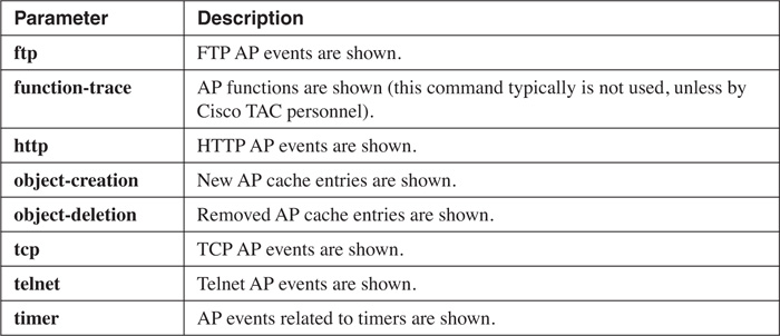
For detailed troubleshooting of AP, you can use the debug ip auth-proxy command. Here is the syntax for this command:
Router# debug ip auth-proxy {ftp | function-trace | http |
object-creation | object-deletion | tcp | telnet | timer}
Table 14-2 describes the parameters for this command.
AP Examples
Now that you have a basic understanding of how to set up AP, I use a couple of examples to illustrate the configuration of AP. The next two sections cover these examples.
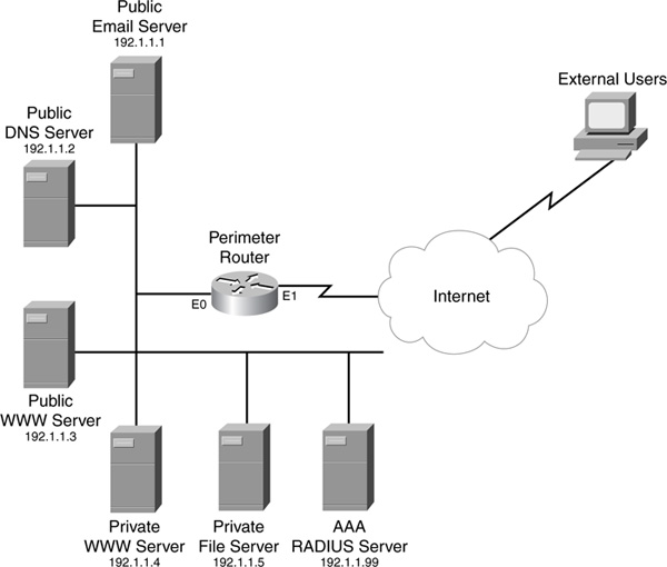
Simple AP Example
This first example uses a simple network with simple policies (see Figure 14-3). This example concerns only outside-to-inside access (the next example throws in NAT and CBAC, to make the scenario more complex). This example wants to allow outside access to the public services, but it requires authentication through HTTP to access the private services. Note that the private file server does not support HTTP; therefore, external users must authenticate by using HTTP to connect to the private web server.
Example 14-9 displays the configuration for the router in Figure 14-3.
Example 14-9 A Simple AP Configuration Example
Router(config)# aaa new-model (1)
Router(config)# radius-server host 192.1.1.99 key cisco (2)
Router(config)# aaa authentication login default group radius (3)
Router(config)# aaa authentication login console-override
group radius enable
Router(config)# aaa authorization exec default group radius (4)
Router(config)# aaa authorization auth-proxy default (5)
group radius
Router(config)# ip http server (6)
Router(config)# ip http authentication aaa (7)
Router(config)# ip auth-proxy inactivity-timer 10 (8)
Router(config)# ip auth-proxy name check-outside http (9)
list check-these
Router(config)# ip access-list extended check-these (10)
Router(config-ext-nacl)# permit tcp any host 192.1.1.4 eq www
Router(config-ext-nacl)# deny ip any any
Router(config-ext-nacl)# exit
Router(config)# ip access-list extended protect (11)
Router(config-ext-nacl)# permit tcp any host 192.1.1.4 eq www
Router(config-ext-nacl)# permit tcp any host 192.1.1.1 eq smtp
Router(config-ext-nacl)# permit udp any host 192.1.1.2 eq dns
Router(config-ext-nacl)# permit tcp any host 192.1.1.3 eq www
Router(config-ext-nacl)# deny ip any any
Router(config-ext-nacl)# exit
Router(config)# interface ethernet1
Router(config-if)# ip access-group protect in (12)
Router(config-if)# ip auth-proxy check-outside (13)
Router(config-if)# exit
Router(config)# line console 0
Router(config-line)# login authentication console-override (14)
Router(config-line)# exit
Router(config)# enable secret ocsic
Here is an explanation of this example, with reference to the numbering on the right side of Example 14-9:
1. This enables AAA.
2. This defines the RADIUS server used for AAA.
3. This enables login authentication, which is required for AP. However, two commands are used. The first command provides the default method for authentication: RADIUS. The second command is used for console access (see Statement 14) and has a backup method (the privileged EXEC password) if the RADIUS server is not available.
4. If a user is authenticated, only specific authorized users can gain EXEC access to the router. In other words, I do not want to allow external AP users to access the EXEC shell of the router; instead, I define the list of authorized users on the RADIUS server.
Caution
It is important that you use this aaa authorization command. You definitely do not want any authenticated user access to the shell. AP users should be allowed access only to other services, not the EXEC shell on the router itself.
5. Authorization for AP is enabled by using RADIUS—if the RADIUS server is not reachable, the AP users are denied access.
6. This enables the router’s HTTP server function.
7. This enables AAA authentication for the HTTP server function.
8. This changes the idle timeout for AP cached information from 60 to 10 minutes.
9. This defines the AP policy: Only HTTP connections listed in the ACL called check-these (see Statement 10) are authenticated. This is important because I want to verify access to the private servers, but I do not want to use AP for the public server.
10. This defines which connections require AP (only those to the private web server).
11. This defines access from the outside world to the inside resources. Notice two things: You must allow the AP connection (the first entry in the ACL), and you should deny anything else, including access to the private file server (this is allowed by the UAP defined on the RADIUS server).
12. This activates the external ACL inbound on the external interface.
13. This activates the AP policy on the external interface.
14. This overrides the default authentication method on the console (below this is the encrypted privileged EXEC password used as the second login method for the console port (see the statement immediately after no. 3).
Complex AP Example: CBAC and NAT
This example uses a more complicated setup in which the router is performing CBAC and NAT, as well as AP. The network in this example is shown in Figure 14-4. In this example, NAT is required because the internal resources are using a private address space: 192.168.1.0/24. Also, CBAC is used to provide a stateful firewall function. For the internal users, all users must be authenticated through HTTP before they can access the Internet: This can be done through an HTTP connection to the router or through an HTTP connection to any Internet web server. Per-user downloadable ACLs are configured on the RADIUS server, defining what specific user groups are allowed to access on the Internet. External users automatically can access the public servers; however, to access the private servers, they first must authenticate through AP by connecting to the private internal web server.

Example 14-10 displays the configuration for the network shown in Figure 14-4.
Example 14-10 AP Example with CBAC and NAT
Router(config)# ip inspect name CBAC-leaving http (1)
Router(config)# ip inspect name CBAC-leaving ftp
Router(config)# ip inspect name CBAC-leaving realaudio
Router(config)# ip inspect name CBAC-leaving smtp
Router(config)# ip inspect name CBAC-leaving streamworks
Router(config)# ip inspect name CBAC-leaving udp
Router(config)# ip inspect name CBAC-leaving tcp
Router(config)#
Router(config)# ip inspect name CBAC-entering http (2)
Router(config)# ip inspect name CBAC-entering ftp
Router(config)# ip inspect name CBAC-entering realaudio
Router(config)# ip inspect name CBAC-entering smtp
Router(config)# ip inspect name CBAC-entering streamworks
Router(config)# ip inspect name CBAC-entering udp
Router(config)# ip inspect name CBAC-entering tcp
Router(config)#
Router(config)# ip nat inside source static (3)
192.168.1.0 192.1.1.0 /24
Router(config)#
Router(config)# aaa new-model (4)
Router(config)# radius-server host 192.1.1.99 key cisco (5)
Router(config)# aaa authentication login default group radius (6)
Router(config)# aaa authentication login console-override
group radius enable
Router(config)# aaa authorization exec default group radius (7)
Router(config)# aaa authorization auth-proxy default (8)
group radius
Router(config)#
Router(config)# ip http server (9)
Router(config)# ip http authentication aaa (10)
Router(config)# ip auth-proxy inactivity-timer 60 (11)
Router(config)# ip auth-proxy name check-outside http (12)
list external-AP
Router(config)# ip auth-proxy name check-inside http (13)
list internal-AP
Router(config)#
Router(config)# ip access-list extended external-AP (14)
Router(config-ext-nacl)# permit tcp any host 192.1.1.4 eq www
Router(config-ext-nacl)# deny ip any any
Router(config-ext-nacl)# exit
Router(config)#
Router(config)# ip access-list extended internal-AP (15)
Router(config-ext-nacl)# permit tcp 192.168.1.128 0.0.0.127
any eq www
Router(config-ext-nacl)# deny ip any any
Router(config-ext-nacl)# exit
Router(config)#
Router(config)# ip access-list extended protect-from-inside (16)
Router(config-ext-nacl)# permit tcp 192.168.1.128 0.0.0.127
any eq www
Router(config-ext-nacl)# deny ip 192.168.1.128 0.0.0.127 any
Router(config-ext-nacl)# permit host ip 192.168.1.1 any eq smtp
Router(config-ext-nacl)# deny ip any any
Router(config-ext-nacl)# exit
Router(config)#
Router(config)# ip access-list extended protect-from-outside (17)
Router(config-ext-nacl)# permit tcp any host 192.1.1.4 eq www
Router(config-ext-nacl)# permit tcp any host 192.1.1.1 eq smtp
Router(config-ext-nacl)# permit udp any host 192.1.1.2 eq dns
Router(config-ext-nacl)# permit tcp any host 192.1.1.3 eq www
Router(config-ext-nacl)# deny ip any any
Router(config-ext-nacl)# exit
Router(config)#
Router(config)# interface ethernet0
Router(config-if)# description **Inside Interface**
Router(config-if)# ip access-group protect-from-inside in (18)
Router(config-if)# ip auth-proxy check-inside (19)
Router(config-if)# ip inspect CBAC-entering out (20)
Router(config-if)# ip nat inside (21)
Router(config-if)# exit
Router(config)#
Router(config)# interface ethernet1
Router(config-if)# description **Outside Interface**
Router(config-if)# ip access-group protect-from-outside in (22)
Router(config-if)# ip auth-proxy check-outside (23)
Router(config-if)# ip inspect CBAC-leaving out (24)
Router(config-if)# ip nat outside (25)
Router(config-if)# exit
Router(config)#
Router(config)# line console 0
Router(config-line)# login authentication console-override (26)
Router(config-line)# exit
Router(config)# enable secret ocsic (27)
Here is an explanation of this example, with reference to the numbering on the right side of Example 14-10:
1. This defines the CBAC inspection rule for traffic leaving the network. This is activated on the external interface (ethernet1) in the outbound direction (Statement 24).
2. This defines the CBAC inspection rule for traffic entering the network. This is activated on the internal interface (ethernet0) in the outbound direction (Statement 20).
3. This creates the static translations for the inside private (local) addresses to public (global) addresses: 192.168.1.0/24 to 192.1.1.0/24.
4. This enables AAA.
5. This defines the AAA RADIUS server.
6. This defines authentication for login and console access (console access has a second method, the privileged EXEC password).
7. This defines authorization for EXEC access, thereby restricting AP users from gaining EXEC access on the router. This authorization needs to be defined on the AAA server and should permit only network administrators.
8. This enables AP authorization for AAA through RADIUS.
9. This enables the HTTP server on the router.
10. This enables HTTP authentication for AP users.
11. This increases the AP idle timer to 60 minutes.
12. This creates an AP policy for external users. HTTP is used for the authentication method, and only access to the private web server triggers authentication (external-AP ACL, defined in Statement 14).
13. This creates an AP policy for internal users. HTTP is used for the authentication method, and only internal users (192.168.1.128 to 192.168.1.255) are authenticated (internal-AP, defined in Statement 15). Additional downloadable ACLs can be created for the users’ groups to restrict external access.
14. This defines when AP occurs for external users accessing the private web server.
15. This defines when AP occurs when internal users access the Internet.
16. This allows internal devices access to the Internet. The first ACL statement admits the AP. The second statement denies everything else from internal users. However, downloadable ACLs defined on the AAA server can allow users access to other resources. The third statement in the ACL allows the e-mail server to send e-mails to other e-mail servers. This ACL is activated in ethernet0 in the inbound direction (see Statement 18).
17. This filters traffic from the Internet as it enters this network. The first statement allows the AP process to take place to the public server. The next three statements allow external users to the public servers—web, DNS, and e-mail.
18. This activates the ACL that blocks internal traffic from leaving the network.
19. This activates the internal AP policy about restricting internal users from accessing Internet resources.
20. This activates the CBAC inspection rule that allows Internet traffic back through the inside interface as it is sent from internal servers as a reply to external user requests.
21. This specifies the inside interface for NAT.
22. This activates the external ACL on the external interface, blocking Internet traffic.
23. This activates the external AP policy to authenticate users from the Internet.
24. This activates the CBAC inspection rule that allows returning traffic to the Internet.
25. This specifies the outside interface for NAT.
26. This overrides the default AAA login authentication rule to use for console access.
27. This configures the privileged EXEC password, which is used as the second authentication method for console access if the RADIUS server is not reachable.
Tip
As you can see from this example, when you start adding more features to your router’s configuration, your task becomes more complex. In this example, I highly recommend that you do the configuration in small pieces. In this example, configure NAT first and then the ACLS, then CBAC, and finally AP.
Summary
This chapter showed you the basics of authentication proxy. Unlike with lock-and-key, you have much more flexibility and control over the authentication and authorization process. When you have different access policies for different users, AP is a better solution than lock-and-key. However, AP requires the use of an external TACACS+ or RADIUS security server. AP enables you to authenticate users through HTTP, HTTPS, Telnet, or FTP with the right version of the Cisco IOS.
Next up is Chapter 15, “Routing Protocol Protection,” which shows you how to protect the router’s routing protocols, as well as implement solutions to reduce your router and network exposure to attacks through some routing tricks.