
This chapter covers the following topics:
As voice over IP (VoIP) technology becomes mainstream, the conferencing and collaboration markets are following its lead. Enterprise networks are deploying new conferencing technology using IP networks, and Internet service providers (ISP) are hosting new services.
Gains in the speed of digital signal processors (DSP) allow newer endpoints to use more advanced compression algorithms to provide better voice and video quality over a range of bit rates. In addition, communication transport costs have dropped drastically over the past few years, making voice and video conferencing across geographic regions extremely cost-effective. These technologies, together with integrated web collaboration, result in conferencing systems that bring significant productivity gains to businesses. For example, integrated web collaboration allows presenters to share their presentation or their PC desktop with other participants in the meeting using a browser. Participants may invoke chat sessions publicly or privately during the meeting, thus providing a common experience for all the participants and eliminating the need to e-mail documents to other meeting members in advance.
This chapter covers the various types of voice/video conferences, along with the associated conference characteristics and features.
The three main conferencing models are ad hoc, reservationless, and scheduled conferencing modes.
Ad hoc conferencing is the most basic model and has the fewest features. It is also the easiest for the end user to create, because ad hoc conferences are simply created with the Conference button on the user’s phone.
Reservationless conferencing is the next most basic model and usually is created using the telephone keypad, after the user has called into the conference bridge. Both ad hoc and reservationless are immediate meetings, created quickly for this instant in time.
Scheduled conferences are more complex and have the largest set of conferencing features. They are placed on the system calendar for some point of time in the future and require more input from the meeting organizer than reservationless meetings.
As previously stated, ad hoc conferences are the simplest form of meeting. Phone users create them in two ways:
When the meeting host presses the Conference button on the phone. The conference functionality enables a user to escalate an existing two-party call into one with multiple participants.
By using the Meet Me option on the phone.
Ad hoc meetings do not reserve resources in advance and do not require participants to interact with a voice user interface before joining the meeting.
The Conference button on the phone creates an ad hoc conference by expanding a two-party call into a multiparty conference.
Consider the following call scenario:
Bob places a call to Alice, and Alice answers.
Bob decides to include Fred in the call. Bob presses the Conference button to put Alice on hold.
Bob places a call to Fred, and Fred answers. Bob announces that he will include Fred in the preexisting conversation with Alice.
Bob presses the Conference button again to connect Fred into the previously established call with Alice, creating an ad hoc conference among the three participants.
Any one of the participants can repeat this sequence of steps to invite more people, until a maximum number of participants (set by the system administrator) have been added to the conference.
Ad hoc conferences created using the Conference button are “dial-out”meetings only; external participants may not dial into the meeting, because the conference has no specific telephone access number or meeting identification.
In addition, participants join ad hoc meetings directly; they do not hear prompts, and the system does not play prompts to other participants as callers join or leave.
The conference initiator also has the option to remove the last participant added, via another button on the phone. Reasons for removing the last participant include times when only brief consultation is desired with the last caller, and the person is not needed for the remainder of the meeting. Another possibility is that the last person called was not there, and the call entered the voice-mail system. For Cisco Unified CallManager systems, the RmLstC button provides this feature. Depending on the type of phone and display system, the phone might present a list of participants. For these phones, other users can be selected for removal, in addition to the last person added.
A Meet Me conference is one in which a number of destination telephone numbers are set aside for conferencing purposes. Each number corresponds to a unique conference that users can join on an ad hoc basis. Administrators set up these numbers by configuring the local phone system to forward these calls to a conference server. After the phone system redirects the calls, the conference server manages them independently. When these numbers are known, any caller can join them.
Security consists of the conference system playing specific tones to the conference when callers join or depart. The meeting participants can then ask new participants to identify themselves.
Consider the following call scenario:
Bob presses the Meet Me button on the telephone to create a conference.
Bob enters a desired Meet Me telephone number. If the number is not currently in use, a conference server creates the conference immediately, and Bob connects to the conference.
After Bob sets up the conference, Alice and Fred simply dial the Meet Me telephone number to join the conference on the conference bridge. Anyone knowing the number may call in. When you use a Cisco Unified CallManager phone system, the default maximum number of participants is four. This is a configurable value.
Meet Me conferences may optionally play entry or exit tones as participants join and leave the conference.
Reservationless meetings are more feature-rich implementations than Meet Me conferences. The following section describes reservationless meetings.
Reservationless meetings are an alternative to scheduled meetings and are used when the meeting organizer quickly wants to place a meeting on the calendar without specifying the number of expected callers or the duration. For this conference type, the meeting organizer specifies a meeting name and creates a meeting identifier (or may request that the system generate one).
Unlike scheduled meetings, reservationless conferences are created immediately upon request. Resources are managed on a first-come, first-served basis.
The person hosting the meeting generally dials into the conferencing system and creates a meeting instance via the Interactive Voice Response (IVR) system.
Another type of reservationless meetings is an open-ended or continuous meeting. This meeting type is always active and can be joined at any time.
Scheduled conferencing allows the meeting organizer to specify resource-related items such as the number of participants, via a user interface provided by the conferencing system. Scheduled and reservationless meetings can be published on a roster or web page, allowing participants to locate and join the conference.
Some schedulers provide a telephone user interface (TUI) for participants who need to schedule conferences via their telephone keypad.
Another key feature of many conference systems is integration with calendaring systems such as Microsoft Outlook. This integration provides the meeting organizer with a central point for creating a meeting, inviting participants, and reserving the required conferencing resources.
A scheduled conferencing system has the real, practical advantage of allowing the system to be sized smaller than the peak demand. For example, if you cannot reserve at 10 a.m., perhaps you will hold your meeting at a less-busy time during the day instead. This is far superior to getting a busy signal, which is what happens if a reservationless system is undersized.
When creating a scheduled meeting, the meeting organizer might specify the resources required to support the number of participants and whether a meeting should support video callers. The organizer also specifies the start and end times of the meeting.
Because conferencing system resources such as dial-in capacity and audio processing power are finite, the scheduling system must manage these facilities. The conferencing system’s scheduler must ensure that a meeting will actually have the resources available at the specified time to accommodate the expected number of callers. This accounting is generally referred to as a reservation.
Resource reservation guarantees the required resources will be there when the meeting begins. Schedulable resources in a conferencing system include some number of access ports. For each caller, one port is consumed. For non-IP-based systems, such ports may be channels on a digital telephone trunk line. In the case of IP-based systems, there is generally a system limit on the number of allowed media connections.
Depending on the configuration, this guarantee can be somewhat of an illusion because of the practice of overbooking. When the system administrator configures a conferencing system for overbooking, it is possible to reserve more access ports than actually exist. The main benefit of overbooking is to allow real resource utilization to be maximized, because many times ports that are reserved for a meeting go unused. Participants might not call in, or the person scheduling the meeting overestimates the attendance. These ports are then available for other meetings. The downside to using overbooking is that it is possible that some reservations might not be honored at meeting time.
Scheduled and reservationless meetings have identifiers in the form of a meeting name and meeting identification number, also called the meeting ID. The meeting ID is a string of digits that allows callers to identify and join the desired meeting. When joining by telephone, the participant specifies the desired meeting by entering the digit string from the telephone keypad. The meeting organizer may specify the digit string or request that the conferencing system generate it automatically.
Common methods for creating scheduled meetings include the following:
Web browser interface—. Most conference scheduling interfaces provide a central, web-based conferencing portal. A portal is a web server providing browser access to the conferencing system’s user and administrative interfaces. The portal allows users to log in and schedule conferences, view future conferences, and join and control active conferences. The conference portals also list the dial-in access information for conferences.
Via the telephone—. This method allows a user to dial into the conferencing system, log in, and schedule meetings by means of the telephone keypad. The user follows voice prompts, entering the required information.
Microsoft Outlook integration—. Some conferencing systems are integrated with e-mail and calendaring systems, such as Microsoft Outlook. With this option, a plug-in is installed into the Outlook calendaring application, which communicates with the conference server. After installation, Outlook presents a new page/tab in the calendar where the meeting details can be entered directly. This integration eliminates the need for the user to bring up a separate browser program.
After the meeting organizer enters the meeting details, the conferencing system reserves resources for the time period specified. This resources reservation ensures that they are available for callers when the conference starts. After the system successfully completes this task, it returns a summary of the information necessary for users to join the conference. This information usually includes the telephone number of the conferencing system, a confirmation of the conference date and time, and some sort of meeting identification number or other identifier. This information can then be sent as a meeting invitation or listed in a meeting roster.
At meeting time, each participant in a scheduled or reservationless conference typically dials the access number provided, which usually connects to an IVR system. The IVR prompts the participant to enter the meeting ID number and might ask the participant to “speak your name at the tone” for a recorded name announcement. When the IVR connects the participant to the conference, the IVR plays the recorded name for all participants to hear. Alternatively, each participant might enter a predefined “profile” number, which the conference server uses to track the participant in the conference. The profile may have a previously recorded name, which is used to announce the new participant.
Depending on how the conferencing system is configured, new participants may be prompted to record their name before joining the meeting. The conference server may then play the recorded name announcement at the time participants join and leave the conference.
After the participant enters the meeting ID and records his name, the conference server might move a new caller to a temporary waiting room until the meeting organizer joins the conference. Or, the meeting organizer can specify that participants proceed directly to the conference.
In another variant of the reservationless meeting, the meeting is tied to a specific dial-in phone number. In this mode, the participants just call the number and are placed directly into the conference, without having to interact with the IVR system.
It is fairly common for conferences to be announced through distribution of a URL link, which brings the users into a multimedia meeting without having them dial in and use the TUI. The user just clicks the provided link through the web browser, and the system identifies the user and dials the user’s phone directly. Over time, this will likely become the predominant attendance method for both voice and video meetings.
Features available during the conference are called in-conference controls. These features enable meeting coordinators to control certain aspects of the meeting. Other features include allowing a participant to initiate a collaboration session. This section provides details about the most common conferencing features.
The whiteboard collaboration feature allows users to share an application window on their computer or their entire desktop with others in the conference. The person sharing might be demonstrating an application or walking through a spreadsheet or other document with the rest of the group. Optionally, other participants can take control and interact with the shared computer, controlling the keyboard and mouse.
The muting and ejecting participants feature allows a conference administrator to mute the incoming voice stream from a participant or remove a participant from the conference. A participant might need to be muted when calling from an environment with much background noise or when the participant has placed the call on hold and music on hold is configured on the participant’s phone.
When a meeting agenda changes, it might be necessary to restrict the attendee list and remove certain participants from the meeting.
Another feature is talk-over mode. This feature lowers the volume at which other participants are heard so that the administrator can be heard clearly when speaking.
Sometimes a meeting chairperson or initiator might want to perform a dial-out operation, either as a courtesy or to control toll charges. Meeting participants can also initiate a dial out to their own phone number, using a web interface.
Sidebars allow participants in a main conference to move to a smaller breakout session. A breakout session is generally used by a small group to work on some aspect of the main topic, after which they may rejoin the main conference. Some sidebar conferences offer a whisper mode, in which participants in a sidebar conference can hear the main conference, but with a reduced volume. This whisper mode enables them to track the activities in the main conference while still discussing the sidebar agenda items.
A typical centralized video conferencing system requires a device that acts as the core entity to receive and redistribute streams. This device is known as a multipoint control unit (MCU).
The MCU terminates all voice and video media streams in a conference and consists of two types of logical components:
A single multipoint controller, generally referred to as an MC or focus
One or more multipoint processors, generally referred to as an MP or mixer
The MP and MC might reside in separate servers or co-reside in a single server.
Note
Note that the terms MP and MC are used by the International Telecommunications Union (ITU) and are generally associated with H.323 signaling. The terms focus and mixer are used by the Internet Engineering Task Force (IETF) in reference to systems using Session Initiation Protocol (SIP) signaling.
The MC controls the conference while it is active and operates on the control (signaling) plane. The control plane is simply the part of the system that manages conference creation, endpoint signaling, and in-conference controls. It negotiates the session parameters with each endpoint and controls all voice and video conferencing resources. The MC does not process the media streams directly.
Whereas the MC exists on the control plane, the MPs operate on the media plane and receive media streams from each endpoint. A basic MCU typically has a single audio MP for audio mixing and a single video MP for composing the video streams. The MPs generate output streams and send them back to the conference participants.
A video MP might be capable of implementing one of several video composition schemes. The MCU is responsible for configuring the MP for the type of video layout (1×1, 2×2, and so on) sent to each participant. The video display output from the MP may vary from participant to participant.
Figure 1-1 shows an example of a video conferencing deployment consisting of a variety of video endpoints and devices. This deployment includes VoIP gateways providing connectivity to the public switched telephone network, endpoints that use SIP and H.323 signaling protocols, and an H.323 gatekeeper (see Chapter 6, “Signaling Protocols: Conferencing Using H.323,” for a discussion of gatekeepers). The diagram also shows other types of video devices, such as endpoints that use H.320 signaling and others that use the Cisco Skinny Call Control Protocol (SCCP).
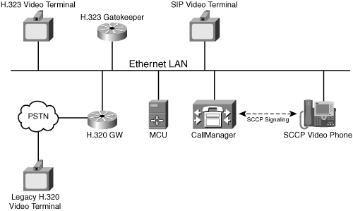
Cisco SCCP devices work together with Cisco Unified CallManager and may appear to the network as either SIP or H.323 devices. The H.320 device is an older type of video endpoint that uses ISDN lines for transporting audio, video, and signaling. For it to participate in the meeting, it connects via an H.320 gateway, which converts the H.320 to the H.323 protocol. Each of these devices may participate in the same video conference if the MCU control plane supports the same list of protocols.
The two main video composition schemes are voice-activated switching and continuous presence. Other schemes may include a combination of voice-activated and continuous presence modes, in which some windows are fixed and others contain the active speaker.
This section describes the various operating modes and features of common video conferencing systems.
In voice-activated switched (VAS) mode, the MCU switches who is seen by others in the conference based on the incoming voice energy level from the various participants. When a new person speaks, the MCU forwards the video stream of the loudest speaker to each endpoint, with one exception: The loudest speaker usually receives a stream of the previous loudest speaker. The reason is that because most endpoints provide a “self view” for each participant, the loudest speaker does not need another self-view stream from the MCU. Some users, however, prefer to know when their image is being transmitted, and MCUs often provide an option in which the active speaker is the only image transmitted.
Because the MCU contains both the audio and video MP for the conference, the audio mixer reports changes in the loudest speaker to the MC, which then commands the video MP to switch to a new set of current and previous video streams.
Because endpoints may have video streams with different stream characteristics from other endpoints (codecs, bit rate, frame rate, picture size), the video MP might need to convert the video streams, depending on the endpoints’ specific receive capabilities.
For example, if endpoints are using different video codecs, the conversion between one codec and another is called transcoding. If the endpoints have different receive capabilities in terms of bit rate, the MCU must adjust the rate at which video is transmitted, using a process called transrating.
Transcoding or transrating requires the video MP to fully decode and then re-encode the video. These processes require DSPs on the MCU. For a voice-activated conference, the processing load is less than what is required for the continuous presence mode. You can find more information in the next section.
Another variant of voice-activated mode is called image passthrough or stream switching mode. In this mode, all endpoints send and receive video streams with the same parameters (codec, bit rate, frame rate, and image size). Because all video streams have the same characteristics, the video MP requires no transrating or transcoding functions.
For this scenario, the MP just forwards the loudest speaker’s video stream to all endpoints except the loudest speaker, after replacing the Real-time Transport Protocol (RTP) headers in the source stream with appropriate RTP headers for each destination endpoint.
Conferences in this mode must have homogenous input and output video streams, each with the same parameters. The video MP does not process the video payload and therefore does not require a DSP.
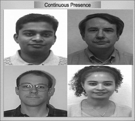
Continuous presence (CP) conferences have the benefit of displaying two or more participants simultaneously, not just the image of the loudest speaker. In this mode, the video MP tiles together streams from multiple participants into a single composite video image, as illustrated in Figure 1-2. CP conferences are also referred to as composition mode conferences or “Hollywood Squares” conferences. The video MP can either scale down the input streams before compositing or maintain the sizes of input streams, generating a larger-size video composite for the output. In CP mode, most MCUs send the same composite video image to all participants.
The manner in which the output stream is divided into subpictures is called the layout, and the mapping of input streams to subpicture locations is called the floor control.
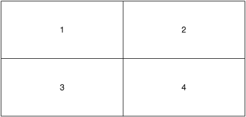
For example, in a 2×2 layout, the screen is divided into four quadrants, and the MCU assigns a participant to each quadrant of the screen, as shown in Figure 1-3.
Many layouts are possible. For instance, the layout may have one subpicture that is substantially larger than the other windows. More-advanced MCUs may allow each end user to select a different layout, selectable via the telephone keypad, a conference portal web page, or special buttons on an IP phone. Cisco 79xx IP phones have a vid-mode button that enables users to toggle between two preconfigured layouts.
Some conference bridges can support a large number of simultaneously displayed participants. However, unlike VAS conferences, CP conferences require a significant amount of processing power, because the video MP must decode all video streams included in the composite video image. The number of simultaneously supported layouts is usually quite limited because of the processing power required to generate the various composite images.
Layouts with multiple pictures may have fixed image locations, or they can change dynamically as participants join and depart. Dynamic subpictures may display different participants over time. One dynamic layout option displays a variable number of subpictures; when a new participant joins the conference, the MC creates a new layout with an additional subpicture for that participant. As participants depart, the MC changes the layout to show fewer (but larger) subpictures.
Within a layout, the floor control policy determines how the media processor maps participants to subpictures. In addition, the floor control decides whether subpictures are locked or dynamic. A locked subpicture continues to display the same participant until that person leaves the conference or the conference organizer changes the subpicture source stream.
Floor control also allows certain privileged users to gain access to a shared resource, such as a remote device or media stream, and change the behavior for themselves or others. For example, a moderator might need to reposition a remote camera.
Some MCUs may also support a hybrid presentation, using a combination of both voice-activated and composition mode. For instance, voice-activated switching can be used for the largest subpicture, to show the person who is currently speaking. Other nonspeaking participants appear in smaller subpictures, as illustrated in Figure 1-4. The maximum number of pictures shown in a layout is a configurable option, set by the system administrator.
One presentation variant is called lecture mode. This mode uses a layout with a large subpicture showing the lecturer. Video streams of students occupy smaller subpictures. The lecturer subpicture is locked, and the student subpictures operate in continuous presence mode with voice-activated priority, so that a student asking a question becomes active in one of the smaller subpictures.
The lecturer may receive a video stream with a different layout than the layout presented to students. The lecturer’s video stream could display a single picture in which a different student is shown based on a time interval.
Another floor control variation is called round-robin mode. In this mode, the main image cycles through all the participants over a period of time.
Conferencing endpoints fall into three categories, based on the feature set:
Low-end desktop systems
High-end room systems
Ultra-high-end telepresence systems
The following sections describe all three categories.
Low-end video conferencing products include desktop endpoints. When compared to high-end systems, the main difference is the maximum bit rate supported by the encoder in the sending direction. Other components in desktop endpoints include the following:
An inexpensive camera that generates more noise than a high-end model, which paradoxically results in a higher encoded video bit rate for the same quality. In addition, the fixed cameras do not allow remote control via far-end camera control (FECC).
For PC-based systems, client-side encoding or decoding on the PC rather than on DSPs.
Video display on a computer monitor, which is often too small to use in a conference room.
High-end room conferencing systems are common in medium- to large-size companies. These systems have high-quality optics and dedicated real-time codecs, which produce excellent video quality at bit rates that range up to 1922 kbps. They support one or more S-video/composite displays and often support computer monitors at resolutions up to 1024×768.
At the extreme high end of room conferencing is the telepresence system. These systems use studio-quality high-definition cameras, large display systems, and special room lighting to provide a life-size view of the remote conference room and participants. Discrete multichannel, high-quality speaker systems and spatial audio codecs provide a vastly improved experience over traditional room conferencing systems.
Some systems such as the Hewlett-Packard HALO video collaboration system require a special HP-managed fiber-optic network to provide features that require very high bandwidth.
Telepresence systems generally include an additional high-resolution camera for sharing the image of a physical object, illustration, or design.
Far-end camera control (FECC) enables a user to control the camera position of a remote endpoint and is a feature often found in high-end room systems. It typically requires a camera with a motorized pivot that can rotate with two degrees of freedom (up/down and left/right). Options for control include zoom, pan (left/right rotation), and tilt (up/down rotation).
Video conferencing systems use one of two FECC protocols:
H.323—. H.323 annex Q describes the standard FECC protocol for IP networks.
H.224—. The second, older scheme (pre-annex Q) uses an ISDN-like H.224-based High-Level Data Link Control (HDLC) frame.
In both cases, endpoints open a low-bandwidth data channel to carry the FECC transmissions encapsulated in IP packets. The packets are transmitted from the endpoint initiating the camera movement to the MCU. The MCU then relays the packets to the far-side endpoint with the camera to be moved. Depending on the protocol used by the endpoints for FECC, the MCU might have to convert the FECC messages from annex Q to H.224 or vice versa. To save bandwidth, the FECC channel might close after a period of inactivity.
At connection time, endpoints exchange FECC protocol capabilities and negotiate which protocols to use, if any. If the remote device indicates it does not support FECC, the user interface on the local device often shows the FECC option “grayed out” (not selectable).
In H.323, two endpoints negotiate FECC protocol formats using the Terminal Capabilities Set (TCS) messages. Older endpoints support only the H.224 scheme, and others use the annex Q mechanism. Some H.323 endpoints support both annex Q and H.224 protocols.
The Internet Engineering Task Force (IETF) has not yet defined any standards for how to transport FECC messages between endpoints. Therefore, endpoints using IETF call signaling standards such as SIP generally use proprietary methods to transport FECC. This has resulted in interoperability issues among different manufacturers.
Because proprietary methods of FECC may also appear in H.323 endpoints, FECC interoperability among different endpoint manufacturers is problematic at best.
Video image processing within the conferencing server may allow a text overlay within a presentation window (subpicture). This text overlay can display identifying information such as the caller’s name or phone number. The text generally appears as a small semitransparent overlay on top of the video image. The conference organizer can often configure the degree of opacity, font, font size, and color.
This chapter provided an overview of voice and video conferencing systems. The chapter discussed the various modes in which conferencing systems operate and briefly described the components that comprise a system. In addition, you learned about the features available in each conference type and how the user interacts with and invokes them.
The chapter closed with a description of the three tiers of video conferencing endpoints currently available in the marketplace and a description of their features.
The next chapter provides an in-depth look at conferencing architectures and the components that comprise a conferencing system.