
This chapter covers the following topics:
Although multimedia conferencing is migrating toward SIP signaling, as described in Chapter 5, “Signaling Protocols: Conferencing Using SIP,” many organizations continue to have a significant investment in legacy H.323 endpoints. This chapter provides a general overview of basic H.323 signaling concepts.
H.323 is a widely deployed International Telecommunication Union (ITU) standard, originally established in 1996. It is part of the H.32x series of protocols and describes a mechanism for providing real-time multimedia communication (audio, video, and data) over an IP network. In this chapter, the intent is to familiarize you with some of the basic concepts involved in the H.323 architecture and signaling models, with an emphasis on voice and video conferencing. It does not attempt to cover all aspects of H.323 networking.
Additional standards referenced under the H.323 umbrella include H.225.0, Q.931, H.245, and Real-time Transport Protocol / RTP Control Protocol (RTP/RTCP). The ITU standards for H.225 and H.245 describe the H.323 session and media control signaling, which are reviewed in this chapter.
Components of an H.323 network include media-terminating devices such as phones, video conferencing terminals, gateways, and multipoint conferencing units (MCU, for hosting meetings). Devices in this group are categorized as endpoints in the H.323 network. Other components include gatekeepers and H.323 border elements. Gatekeepers provide services such as a network dial plan and bandwidth management for endpoints. The H.323 border element connects two H.323 networks to provide call routing and authorization between the networks. Because this chapter focuses on voice and video conferencing, the emphasis is primarily on endpoints.
In the following section, the individual components comprising an H.323 stack are reviewed. Figure 6-1 shows the basic components of the H.323 signaling stack.
H.323 stack components can be separated into two main categories: signaling and media.
Signaling components include the following:
H.225.0 call signaling—. H.225.0 provides a mechanism for initiating calls between devices.
H.225.0 RAS—. Registration, Admission, and Status (RAS) provides controls on bandwidth utilization and endpoint location.
H.245 media control—. H.245 provides a mechanism for negotiating media types and characteristics between endpoints.
H.323 media components include the following:
Audio and video codecs—. Codecs provide the method for encoding and decoding media streams.
RTP and RTCP stacks—. RTP and RTCP provide a mechanism for transporting and managing media packet data over an IP network. Chapter 4, “Media Control and Transport” discusses this topic in depth.
The following sections provide details about H.323 endpoint addressing and call establishment.
When making calls between devices using H.323, a calling device can specify the called party using a number of schemes. H.323 provides several methods for addressing and identifying endpoints, including the following:
E.164 Dialed Digits
H.323 ID
URL ID
MobileUIM
E-mail ID
Transport address
The E.164 Dialed Digits addressing scheme assigns a dialed digit string to each device and is one of the more familiar modes of endpoint aliasing. The dialed digit string is based on the ITU-T E.164 standard, which describes the numbering plan for international public telecommunications. E.164 numbers may include any digits between 0 and 9 and have a recommended maximum of 17 digits. H.323 network administrators assign numbers according to a dial plan. The dial plan establishes the dialing pattern to reach specific endpoints in the network. An endpoint that wants to call another endpoint does so by calling the assigned destination number of the other party.
The H.323 ID is a string-based alias assigned to the endpoint, such as conferenceroom222 or johnsmith. These types of IDs are useful only locally and typically are used between endpoints and gatekeepers. The role of an H.323 gatekeeper is explained later in this chapter.
The H.323 URL ID has the format h323:user@hostname, where the user field identifies the service or user and the hostname contains either an IP address or DNS hostname. Examples include h323:[email protected], h323:[email protected], and so on. This format of endpoint identification provides a mechanism for web-based, clickable dialing and eliminates specific dial plan routing issues.
The MobileUIM field is used with wireless networks. It permits interworking between devices, as described in ITU-T standard H.246 Annex E.1.
H.323 calls may be placed using an e-mail ID as the called endpoint address. The e-mail ID is an RFC 822–compliant address.
Endpoints connected to a gatekeeper may use the gatekeeper to translate E.164 dialed digits into a transport address.
The H.323 standard also describes other less frequently used methods for identifying an endpoint.
The H.225 recommendation describes the protocol for H.323 session control, including call initiation and connection management. It fully describes how an H.323 call is initiated, established, and disconnected. H.225 is derived from the Q.931 ISDN signaling standard, after modification for packet networks. It is based on Abstract Syntax Notation 1 (ASN.1) encoding. This section reviews common H.225 message types and content.
H.225 uses a reliable TCP connection between devices on the IP network. The device initiating the call opens a TCP connection to the called device, which is listening on TCP port 1720.
H.225 protocol data units follow the same format as Q.931 messages. Figure 6-2 illustrates the header used by H.225 messages.
The following list describes the H.225 message header:
Protocol Discriminator (one octet)—. The Protocol Discriminator identifies the Layer 3 protocol. For Q.931 messages, this value is always 8. It distinguishes user-network call control from other messages.
Call Reference Value (one octet)—. This value contains the length of the Call Reference Value (CRV) field, which follows it. The value may indicate a 1- or 2-byte CRV.
Call Reference Value (one or two octets)—. The CRV is used to uniquely identify each active call in progress. The value is assigned at the beginning of the call. Other subsequent requests and responses associated with this call instance carry the same CRV value.
Message Type (one octet)—. The Message Type field identifies the message (for example, Setup, Connect, Call Alerting, and so on). The message type determines what additional information is allowed in the next field, Information Elements.
Information Elements—. The contents of this variable-length field depend on the preceding field, Message Type. The two types of information elements (IE) are single-octet elements and variable-length elements. The IEs carry information related to the message type, such as calling and called number, bearer capability, and so on.
This section describes some of the protocol data units (PDU) used in initiating, establishing, and disconnecting H.323 calls. The PDUs are transmitted over the H.225 signaling channel, and each packet is sent as a whole message. The message is defined using a structure defined by a Transport Protocol Data Unit Packet (TPKT). A TPKT format is defined by IETF RFC 2006 and is used to delimit individual messages within the TCP stream. The TPKT contains a one-octet version ID, followed by a one-octet Reserved field, followed by a two-octet PDU Length field, followed by the PDU itself.
The Setup message is used to initiate a call to a remote device. When an H.323 endpoint initiates a call to a remote device, it first establishes a TCP connection. After the TCP connection has been established, the originating endpoint sends a setup request.
After sending a Setup message, the originating endpoint starts the setup timer. If the terminating endpoint fails to respond within the timer interval, the originating endpoint may retry the setup request or terminate the call.
Mandatory fields in the Setup message include the following:
Protocol Discriminator
Message Type
CRV
Bearer Capability
User-User Information Element (UUIE)
The Bearer Capability field of the Setup message is used to tell the receiver about the nature of the call, such as whether the call is audio only or whether it will be an audiovisual call. The subfield Information Transfer Capability is set to Unrestricted Digital Information for calls that include video data. The Bearer Capability information element is required in the Setup message. It is optional in other messages.
The Setup message may optionally contain fields such as the E.164 number of the called party, the calling party name/number, a fast-start IE, and other information. Fast Connect operations are discussed in a later section of this chapter.
If the receiving device is a Voice over IP to public switched telephone network (VoIP-PSTN) gateway, it examines the called number and may ring a locally attached phone, or it could initiate an outgoing trunk call to the PSTN. In the case of IP-IP gateways, the call is terminated locally by the gateway and reoriginated using H.323 or Session Initiation Protocol (SIP) signaling toward the destination device.
The Call Proceeding message is sent by the called endpoint as an indication that the call is in the process of being established and that no more Call Establishment messages will be accepted for this call instance. Call proceeding is an optional message.
After the called party receives a notification of the incoming call (for example, a phone is ringing), the called party returns an Alerting message.
The Alerting message is an optional status message issued by the called endpoint to the caller. This message confirms that the called endpoint has initiated an indication of the incoming call to the called user (that is, the phone is ringing).
The called device sends a Setup ACK message to the calling endpoint as an acknowledgment of a Setup message.
The Connect message is sent from the called party to the calling party to inform the caller that the call has been answered. The Connect message usually initiates the start of any toll charge accounting. The H.225 connection is complete when the Connect message has been transmitted.
The Notify message allows endpoints to exchange information during the life of the call. One such use is for the called endpoint to return details on its bearer capabilities after the call connects.
Cisco Unified CallManager uses H.225 Notify messages during call transfer to indicate the transferee name and number information to the calling party. That is, when A calls B, and B transfers the call to C, the information about C is sent to A using the H.225 Notify message. In this way, party A can know to whom he or she is speaking.
The Release Complete message may be sent by either endpoint. It indicates that the sender has terminated the call and that the CRV is reusable. No further H.225 signaling is possible for this call after Release Complete is received, and any allocated resources should be released. The Release Complete message contains a return code indicating the reason for call termination. The ITU-T H.225.0 Recommendation contains a full list of call termination cause codes.
Figure 6-3 illustrates the basic call flow for establishing an H.225 connection between endpoints. When the call has reached the Connect state, H.245 media negotiations can begin.
The next section describes H.245 signaling in detail, which is used for negotiating media streams between endpoints.
The H.245 recommendation provides the mechanism for the negotiation of media types and RTP channel establishment between endpoints. Using the H.245 control protocol, endpoints exchange details about the audio and video decoding capability each device supports. H.245 also describes how logical channels are opened so that media may be transmitted. Like H.225, H.245 messages are encoded using ASN.1 notation.
The H.245 session information is conveyed to the calling device during the H.225 exchange. After the Setup message has been transmitted, the called device can use any one of the Alerting, Call Proceeding, or Connect messages to return the IP address and port to be used for the H.245 control session. When the calling endpoint receives the information, it immediately initiates a TCP connection with the specified IP address, and H.245 negotiations start.
Although media can be established before the H.225 Connect message is received, Cisco IOS PSTN gateways do not complete bridging between the IP and the telephony side until the call is fully connected. This prevents two-way audio communication before billing can be started.
The following section describes some of the more important H.245 messages used in media negotiation and control.
This section describes some of the H.245 PDUs frequently used in establishing H.323 media connections. The messages include PDUs for exchanging endpoint decoding capability, determining how endpoints should behave when conflicts arise, and for opening and closing logical channels. Logical channels are opened and closed depending on the decoding capability and requirements of the endpoints. Each H.245 logical channel is numbered. Logical channel 0 is used for the control channel, and it is always assumed to be open as long as endpoints remain connected.
The Terminal Capability Set (TCS) message contains the media and feature capability of the sender. After the H.245 connection is established, each side sends a TCS message to the remote device. The TCS message is the first H.245 message exchanged between connecting endpoints. The receiving endpoint uses this information to determine its options for initiating media streams to the TCS message sender.
The TCS message includes the following:
A list of audio codecs supported, including packetization periods and payload types.
A list of video codecs supported. Video codecs include H.261, H.263 and associated annexes, H.264 (including profiles and levels), picture formats/resolution, maximum bit rates, minimum picture interval (MPI) corresponding to the frame rate, and so on.
The Dual Tone Multiple Frequency (DTMF) relay type supported. Common DTMF relay types include H.245 alphanumeric, H.245 signal, and voice band. Many video endpoints support only voice-band mode. In this mode, DTMF signals are played directly into the audio stream as tones.
Whether the sender supports features such as T.38 fax mode, RFC 2833 DTMF signaling (encoding DTMF digits in an RTP payload format), and the far-end camera control (FECC).
Alternate capability set.
The alternate capability set is a grouping of the individual modes (for example, G.711, G.722, CIF H.263, and so on) that the endpoint is capable of supporting. These alternate capability sets are then grouped into the simultaneous capability set.
As described in the preceding section, H.323 devices use the TCS message to provide a complete list of their receive capabilities. The simultaneous capability set is a subsection within the TCS message, allowing the sender to describe which of the listed capabilities can be used concurrently. The devices specify this in terms of groups of alternate capability sets. For example, an endpoint may have listed some compute-intensive audio and video codecs as receive capabilities, but it may not support using both of them at the same time (because of processor constraints). In such a case, the sender uses the simultaneous capability set to list which combinations are allowed.
For example, an endpoint might have indicated support for H.263 video streams and G.711 and G.723 audio streams. For this example system, when H.263 video is active, only G.711 audio may be used. The simultaneous capability set would then carry a combination of H.263 video and G.711 audio and another with G.723 audio only.
The User Input Indication is used to transmit local digit and hookflash events to the remote endpoint. Depending on the DTMF relay session parameters negotiated during the TCS exchange (alphanumeric versus signal), these indications may contain just the digit itself or the digit and the period of time the digit was pressed (digit duration).
Endpoints supporting out-of-band DTMF relay indicate this support in the receiveUserInputCapability TCS element. The three frequently used values are
Hookflash
DTMF
basicString
The values are Boolean, and when true, indicate that the signaling type is supported. If both the local and remote devices support one or more of these, they may send H.245 User Input Indication messages to convey events when the local endpoint wants to signal a digit or hookflash.
The basicString Boolean value indicates support for DTMF relay for characters 0 through 9, *, and #. The DTMF Boolean value is a superset of basicString. Through the use of Signal and Signal Update messages, the endpoint additionally conveys the time duration the digit was pressed (and the digit itself). If hookflash support is also set to true, the hookflash event is sent with the Signal message.
As an alternative to H.245 DTMF relay, digit events may also be transmitted using RFC 2833 packets in the media stream. RFC 2833 packets are interleaved with media packets, unlike out-of-band DTMF relay, which involves the transmission of User Input Indication messages over the H.245 signaling channel. Because media packets have a higher transport priority, RFC 2833 DTMF signaling is often the preferred digit transport mechanism if intermediate signaling proxies are involved.
Another option used by many video endpoints is to play DTMF tones within the audio stream itself. In this mode, the audio decoder detects the tones and reports them as digits to the control layer.
The Master-Slave Determination (MSD) exchange uses two values to determine which side shall be master and which side shall be slave. After an endpoint sends its TCS, it sends the MSD message.
Endpoints use the result of the MSD exchange to establish roles between each device for the purpose of managing logical channels and to determine how conflicts should be handled. For example, the master has the role of assigning session IDs for logical channels and for generating the key when media encryption is used. The decision as to the master-slave role is returned in the MSD ACK message.
The MSD message contains values for Terminal Type and a randomly chosen Status Determination Number. Each endpoint compares the values received against its own value. The side that has the higher Terminal Type value becomes the master. If both sides have the same value for Terminal Type, the one with the higher Status Determination Number becomes the master. If by coincidence both sides select the same value again, the MSD is rejected and the negotiation retried. When an endpoint connects to a conference server, the conference server is always the master.
In H.323, a logical channel represents a communication path used for media or data transmission. Endpoints use the H.245 OpenLogicalChannel (OLC) messages to create these pathways.
The OLC request can be transmitted after the sender receives a TCS and has completed the MSD exchange. When opening a unidirectional logical channel, the device that will be transmitting data on the channel sends the OLC request. An endpoint sends OLC requests to open audio, video, or other streams, such as those used for FECC. For media, the OLC request carries information such as the codec to be used and the payload type that will be used in the RTP packets.
The specific content of the OLC request depends on the type of stream being opened. For audio streams, the OLC request contains information such as the codec, packetization period, dynamic payload type, logical channel number, whether silence suppression will be used, and RTCP port information. The OLC request is acknowledged using an OLC ACK response. The OLC ACK contains the remote IP address and port to which packets should be transmitted.
After the OLC ACK has been received, RTP streaming may start, and the RTCP channel is opened. The RTCP channel may be used for exchanging RTCP messages, such as the sender and receiver reports. RTCP channels are bidirectional.
Each OLC request includes the forward logical channel number (LCN). The LCN identifies a specific channel and is used as a reference in OLC responses (OLC Acknowledgment or OLC Reject) and when the channel is closed in the Close Logical Channel request.
Figure 6-4 shows an OLC example for an audio stream.
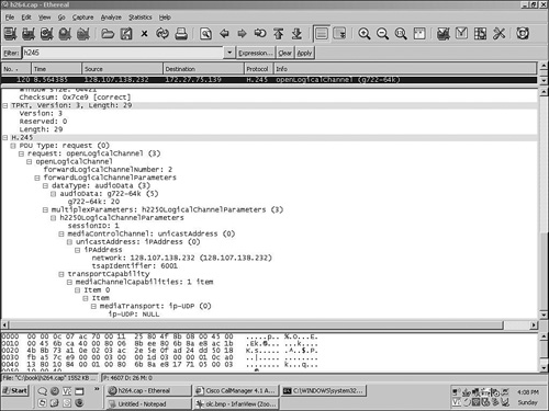
In this example, the request is to open a 64-kbps G.722 audio channel with a 20-millisecond (ms) packetization period. The local IP address for RTCP is 128.107.138.232, and the UDP port is 6001. The forward LCN is 2.
This section provides some details about the video-specific characteristics found in the OLC request for video streams. The OLC request for video streams includes elements such as the video codec, RTP payload type, maximum transmit bit rate, the resolution and frame rate, and the RTCP channel information.
Figure 6-5 shows a typical OLC request for an H.263 video stream. The next section examines the elements contained within the request in detail.
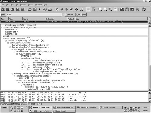
For H.261 and H.263-1996 video encoding, the payload types are static and are specified in RFC 3551 (H.261 uses payload type 0x31, and H.263-1996 uses type 0x34). Newer video codecs such as H.263-1998, H.263-2000, and H.264 use dynamic payload types. In Figure 6-5, an OLC request is shown with h263VideoCapability listed in the Video Data field, along with a bitmap indicating any supported annexes.
The next sections provide additional details about the video elements found in the OLC request shown in Figure 6-5.
The Maximum Bit Rate (maxBit rate) field of the OLC request is specified in units of 100 bits per second. In Figure 6-5, the maximum transmit video bit rate is 3200, or 320 kbps. The OLC receiver must be able to accept an incoming video data rate up to the maximum specified in maxBit rate. This rate must be lower than or equal to the value indicated by the receiver in the TCS it sent earlier. The value refers only to the video streaming rate and does not take into account any overhead from transport headers.
H.263 video supports a number of picture sizes and frame rates. The five standardized picture formats, from smallest to largest, are sub-QCIF, QCIF, CIF, 4CIF, and 16CIF. It is also possible to negotiate custom picture formats.
The specific video picture size and frame rate to be used in a transmission are included in the OLC request. The h263VideoCapability resolution and Minimum Picture Interval (MPI) value, such as qcifMPI=x or cifMPI=x, indicate an image size and the rate at which frames will be transmitted for that size. The value for x is calculated by the following formula:
MPI = 30 / frame rate
The MPI value indicates the expected frame rate at which the sender will transmit video. For example, an MPI of 2 indicates a frame rate of 15 frames per second (FPS), and an MPI of 3 indicates a frame rate of 7.5 FPS.
In Figure 6-5, the h263VideoCapability field indicates cifMPI=1. This informs the receiver that the sender will be transmitting a picture format with Common Interchange Format (CIF) resolution, with a frame rate of 30 FPS.
The h263VideoCapability section of the OLC is also used to indicate special encoding capabilities, listed in terms of annexes. In Figure 6-5, these are shown to be a bitmap, with a value of 1 indicating that the encoder supports the annex, and a value of 0 when it does not.
The OLC request for H.264 streams carries similar information to the H.263 streams but is encoded differently. The transmitting endpoint encodes information about stream characteristics using a Generic Video Capability structure. This same structure may be found in the TCS message. Information carried in the structure includes a maximum transmit bit rate and media encoding characteristics, expressed in terms of an H.264 Profile and Level indication.
H.264 streams carry a dynamic payload type with values in the range of 96 to 127. The value selected is indicated in the dynamicRTPPayloadType field. The valve specified indicates to the receiver that the transmitter will use this designated value for its RTP payload type in all H.264 RTP packets sent on this channel.
The H.264 Profile value describes the characteristics of the video encoding that will be used in the transmitted media stream. The Level value indicates the maximum bit rate and frame rate and the number of macroblocks (MB) per second that will be transmitted. MBs represent fundamental regions within picture transmissions.
Figure 6-6 provides an example of an OLC request for an H.264 video stream. The Generic Video Capability structure carries the maximum bit rate in units of 100 bps. It is shown here as 3840, or 384 kbps. It also contains the H.264 Profile and Level values in an encoded format.
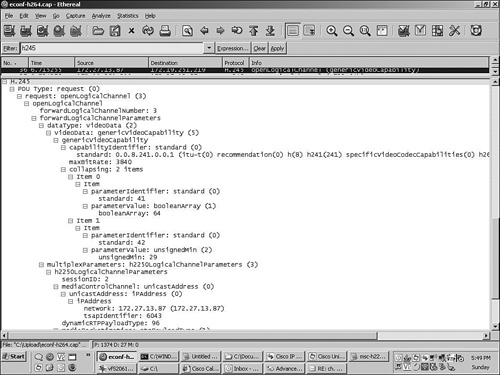
In Figure 6-6, after the maximum bit rate, the next structures of interest are the two parameter identifier/value pairs. The first parameter identifier of 41 indicates that the parameter value content is describing the H.264 profile. The next parameter identifier/value pair describes the H.264 level used for this media stream.
This combination is indicated by a parameter identifier of 42, followed by a parameter value of 29. The parameter identifier 42 indicates that the parameter value describes the H.264 level parameter.
The ITU-T H.241 specification fully describes the profile and level assignments. The profile is a Boolean array, which allows an endpoint to indicate support for one or more of the Baseline (bit 2), Main (bit 3), or Extended (bit 4) profile types. The Baseline profile requires the least computing resources and is frequently used for video conferencing systems.
As described earlier, Figure 6-6 shows a profile value of 64 and a level of 29. Using Table 6-1 and Table 6-2, the Boolean array with value 64 is interpreted as the Baseline profile, and the parameter value of 29 correlates to level 1.2. Table 6-1 and Table 6-2 are excerpts from the ITU-T Specification H.241 (07/2003) and provide details on interpreting the profile and level values.
Table 6-1. H.241-H.264 Capability Parameter: Profile
Parameter | Profile |
|---|---|
Parameter description | This parameter is a Boolean array. |
If bit 2 (value 64) is 1, this value indicates the Baseline profile. | |
If bit 3 (value 32) is 1, this value indicates the Main profile. | |
If bit 4 (value 16) is 1, this value indicates the Extended profile. | |
All other bits are reserved, shall be set to 0, and shall be ignored by receivers. | |
In a decoder capability, each bit set to 1 means that the terminal is capable of decoding the indicated profile(s) using the level and other optional parameters in this Generic Capability. | |
In an OLC message, each bit set to 1 means that the logical channel contents obey all constraints of the indicated profile(s). | |
Parameter identifier value | 41. |
Parameter status | Mandatory. This parameter appears exactly once in each Generic Capability. |
Parameter type | booleanArray. |
Supersedes | This field is not included. |
Table 6-1 describes how to decode the Generic Video Capability parameter found in the OLC request to determine the H.264 profile. The profile defines the encoding complexity and compression characteristics for the video stream.
Table 6-2 shows the correlation between the level parameter as set in the Generic Video Capability structure and the H.264 level number. The level number provides information about the video transmission in terms of the maximum bit rate, number of MBs per second, and frame size.
When a device receives an OLC request, it examines the details of the incoming request and allocates the required resources. Resources may include a digital signal processor (DSP) channel and UDP ports for the RTP and RTCP sessions. After associating the resources with the logical channel, the endpoint returns an OLC ACK to the sender over the H.245 session.
The OLC ACK message contains the RTP and RTCP IP address and port details (to which RTP should be transmitted), along with the LCN associating the OLC ACK with the OLC request.
When an endpoint wants to close a channel it has opened, it sends a Close Logical Channel (CLC) message to the remote device. The receiver of CLC responds with a Close Logical Channel Acknowledgment (CLC ACK) response.
The CLC ACK is transmitted in response to a CLC request. It is not possible for a device to stop a peer from closing its own channels.
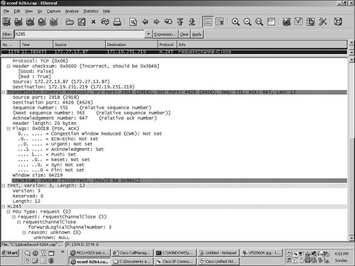
The Request Channel Close message requests that the remote side close a previously opened logical channel. The request includes the LCN and a reason code indicating why the sender requests that the channel be closed.
There are two possible responses to Request Channel Close messages. The recipient may return a Request Channel Close Acknowledgment, indicating the channel will be closed, or it may reject the request. When rejecting the request, the endpoint sends a Request Channel Close Reject, with a cause code field. Figure 6-7 illustrates the Request Channel Close PDU.
This section describes H.245 messages used specifically for video sessions. These commands may be initiated from either side after the video session has been established. These include commands for requesting a device change its video transmission rate, to stop and start video decoding, and to request that a sender transmit an intraframe.
The Flow Control command is a directive from the decoder of the receiving side to the encoder of the transmitting side. The decoder sends the Flow Control message to request that the encoder adjust its maximum transmit bit rate. The two parameters for the Flow Control command include the LCN and a new maximum bit rate. The bit rate is specified in units of 100 bps.
The Miscellaneous Indication message carries several types of indications between video endpoints. This section outlines some common uses.
When an endpoint is muting or unmuting its video transmit stream, the muting endpoint may inform the remote device by sending a Miscellaneous Indication message.
To indicate that a video stream is muted, the Miscellaneous Indication carries an indication type of logicalChannelInactive. When normal transmission begins or resumes, the Miscellaneous Indication type of logicalChannelActive is sent. The Miscellaneous Indication carries the LCN to which the operation applies.
Another indication type is VideoTemporalSpatialTradeoff. This indication is sent to an encoder to request a change in the stream characteristics. The function provided by VideoTemporalSpatialTradeoff signaling is described in detail in the following section.
The Miscellaneous command transports mid-call video requests. The Miscellaneous command may be sent at any time after the logical channel has been established, and it does not receive an acknowledgment.
There are two classes of Miscellaneous command messages:
Encoder control commands
Decoder control commands
The Miscellaneous command carries an LCN identifying the video channel to which the request applies. A partial list of Miscellaneous command request types follows:
VideoFreezePicture—. This command instructs the decoder on the receiver to complete the assembly of the current video image and then display it without further change until the sending side releases it. The release occurs when the transmitter sends an intraframe video bitstream with the Freeze Picture Release bit set to true. After the release has been received, the decoder resumes decoding and displaying.
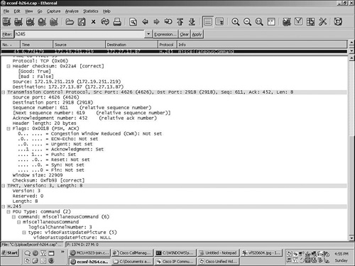
VideoFastUpdatePicture—. This command is sent by an endpoint receiving a video stream. It instructs the encoder at the sender to complete the encoding of the current frame and then to generate and transmit a full intraframe as soon as possible. VideoFastUpdatePicture is sent whenever an endpoint needs to receive a full reference frame to continue decoding.
VideoFastUpdateGOB—. VideoFastUpdateGOB instructs the encoder to update one or more group of blocks (GOB). A GOB is a subset of a picture frame and consists of a group of MBs in scan order.
VideoTemporalSpatialTradeoff—. VideoTemporalSpatialTradeoff is sent by an endpoint receiving a video stream and requests that the encoder change its trade-off between temporal and spatial resolution. It uses an index from 0 to 31, with higher numbers requesting a higher frame rate.
If the encoding device supports VideoTemporalSpatialTradeoff, it sets the corresponding bit in the forwardLogicalParameters field of the OLC request. Upon receipt of the OLC ACK, the encoder transmits a VideoTemporalSpatialTradeoff indication with its initial value. The decoding side may request a new value by sending a request to the encoder.
In Figure 6-8 (taken from an Ethereal trace), the sender has requested a VideoFastUpdatePicture for LCN 3. When this message arrives at the remote device, its encoder generates an intraframe (I-frame) and transmits it to the requesting device over the RTP stream corresponding to LCN 3.
When the H.225 session is connected, the H.245 media negotiations can begin. The message sequence chart in Figure 6-9 illustrates the end-to-end H.245 negotiations required to establish bidirectional audio and video streams. In this example, a two-way H.264 video call is established.
The H.323 Fast Connect feature is an optimization added as part of H.323 Version 2. Fast Connect signaling can establish media streams in a point-to-point call with one round-trip message exchange, enabling immediate media exchange after the call has been connected. When Fast Connect mode is not used, the media connect is established using standard H.225 and H.245 signaling, called Slow Start mode.
Users with endpoints that use H.323 Slow Start signaling may experience audio clipping because of the delay caused by the additional H.245 message exchanges after the connect. In these cases, the initial speech of the called party can be lost, because the media may not be fully established by the time the called party begins speaking. In Fast Connect mode, this scenario is minimized because the media channels are established with significantly fewer message exchanges.
Other improvements include tunneling H.245 messages over the same TCP connection used for H.225 signaling, and Early H.245 mode, in which the H.245 channel is opened as early in the H.225 call sequence as possible.
When an endpoint is using Fast Connect mode, the Fast Start element is added to the H.225 Setup message. The Fast Start element carries an embedded OLC request, a suggested codec, and a set of reverse logical channel parameters.
The reverse logical channel parameters carry the codec, IP address, and port numbers for RTP and RTCP sessions for the calling endpoint. If the called endpoint also supports Fast Connect and accepts the codec, it may immediately start an RTP stream toward the calling endpoint.
The called device responds by placing a similar Fast Start element in the H.225 Connect message, which contains an embedded OLC, along with its set of reverse logical parameters. After these have been exchanged, each side has sufficient information to establish a two-way media exchange.
The H.245 session is still required for other mid-call H.245 messages, such as User Input Indication, CLC, and so on, but it can be established later after the media connects or use the tunneling mechanism over the H.225 session. For a Fast Connect call, the TCS messages are exchanged after the Fast Connect response is received and after media establishment.
H.323 video devices do not generally support H.323 Fast Start mode.
Figure 6-10 shows the messages exchanged for a basic Fast Connect call, without early H.245 mode or H.245 tunneling.
The next section describes the H.245 signaling used to implement simple call hold, resume, and transfer operations.
Basic phone features include the ability to transfer a call to another party and to place a call on hold and resume it later. Calls are placed on hold or transferred by means of the hold and transfer buttons on the phone. As part of the hold and transfer operations, the RTP media channels are closed and reopened again. In the case of hold/resume, the channels are opened to the same phone; for transfer, media resumes with a new device. The next section describes how the Empty Capability Set (ECS) message can be used to provide both of these services. H.323 also includes support for hold, resume, and transfer by means of the H.450.x protocol, but that is beyond the scope of this chapter.
To indicate to the remote device that a hold operation is in progress, the endpoint initiating the hold operation sends a special form of the TCS, known as the ECS message, sometimes referred to as TCS=0.
The ECS is a TCS with all capability fields set to null and support for it is a mandatory part of H.323 Version 2 and later. It does not disconnect the call, but simply informs the remote side that the sender does not currently have any decoding capability. As a result, the remote side closes all logical channels toward the sender. The side going on hold does likewise, media terminates, and the call is placed on hold.
When the call is resumed, the resuming device sends a new TCS message with all supported codecs listed. The normal H.245 negotiations occur, and the call is reestablished.
Call transfer using ECS requires that the phones involved use a common H.323 signaling agent. When a call is connected and the transfer button is pressed, the H.323 call signaling agent in the transferring phone sends ECS to the remote device, and media is closed. When the party to which the call was transferred answers, then the transfer button is pressed again and the H.323 call signaling agent sends a new TCS and negotiates media on behalf of the phone to which the call was transferred.
For instance, suppose that phone A is connected to phone B, and the user of phone A wants to transfer the call to phone C. The user at phone A presses the transfer button, dials the number of phone C, and then presses transfer again. Phone C starts ringing, and the H.323 call signaling agent waits for the user at phone C to answer. When phone C is answered, the H.323 call agent sends a new TCS with the terminal capability of phone C. When phone B receives the new TCS, the logical channels are reopened, and the media is connected between phone B and phone C.
H.323 devices include terminals, gateways, multipoint control units (MCU), and gatekeepers. In the next section, the functions and features provided by each of these common network elements are reviewed in detail.
Terminals are end-user devices and may communicate with other terminals on the network, or with gateways when calling devices on other network types. Terminals include phones and phone systems running the H.323 protocol stack, desktop and room conferencing systems, and personal computers running an H.323 multimedia communications program such as Microsoft NetMeeting. Basic devices provide audio support and can optionally include video or data features, such as a whiteboard or application sharing modes.
H.323 gateways allow interworking between devices on the IP network and devices on other network types, such as the PSTN. The gateway provides transparent signaling and media conversion between packet-and circuit-switched networks, allowing endpoints to communicate with remote devices without regard for the signaling methodology used by those devices.
Figure 6-11 shows an H.323 gateway interconnecting the H.323 and PSTN networks.
MCUs are conferencing systems allowing three or more participants into an audio or video conference call. The MCU manages conferences and provides audio and video mixing services for the meeting participants. Chapter 2, “Conferencing System Design and Architecture,” covers the architecture and features provided by the MCU in detail.
A gatekeeper is an optional H.323 component on the network. When present, it provides important services for terminals, gateways, and MCUs under the control of a system administrator. These services include allowing endpoints to call one another using a dial plan and providing access and bandwidth control. The next section provides details about gatekeeper services.
Endpoints, gateways, and MCUs can be configured to use the services of a gatekeeper. These devices use the RAS protocol for gatekeeper communication. Basics of the RAS protocol are discussed later, in the section “Gatekeeper RAS Signaling.”
The H.323 gatekeeper provides many features, including access control, address translation, bandwidth management, dial plans, and other services that improve scalability of the H.323 network. This section provides an overview of some common gatekeeper features. Endpoints and gatekeepers communicate using the RAS protocol.
The H.323 gatekeeper provides administrative control over an H.323 network. The features provided by a gatekeeper can be separated into two groups: mandatory and optional.
The four mandatory features of an H.323 gatekeeper are as follows:
Address translation—. This feature provides name translation services.
Bandwidth control—. The gatekeeper can grant or deny bandwidth requests between calling and called endpoints.
Admission control—. This service allows the administrator to impose restrictions on endpoint admission to the H.323 network.
Zone management—. Zone management is used for communication with other gatekeepers in the network.
This gatekeeper service translates E.164 numbers and H.323 IDs into endpoint IP addresses. This capability enables an H.323 endpoint to call another endpoint without knowing the IP address of the called device.
Because an H.323 endpoint may make a direct point-to-point call if the caller knows the DNS name or IP address of the remote device, gatekeepers are not required for a basic call. However, allowing calls to be placed between endpoints using symbolic aliases simplifies H.323 client administration. If endpoints use Dynamic Host Configuration Protocol (DHCP), the IP address assigned to the endpoint can change over time, but the alias name remains the same.
Bandwidth control allows the network administrator to configure limits on bandwidth usage for calls initiated by H.323 endpoints. At a minimum, the gatekeeper must have support for the RAS messages: Bandwidth Request (BRQ), Bandwidth Confirm (BCF), and Bandwidth Reject (BRJ).
This service allows the network administrator to control which devices gain access to the H.323 network. Gatekeepers maintain call admission policy and may grant or deny network access based on the system configuration. Admission control is accomplished by using H.225 RAS signaling.
A zone is composed of the devices actively registered with a single gatekeeper and includes terminals, gateways, and MCUs. Each endpoint belongs to only one zone. Large networks may contain multiple zones and gatekeepers. A gatekeeper can communicate with other gatekeepers for purposes of routing calls between devices in different zones. Networks with multiple gatekeepers can be organized in either peer-to-peer or hierarchical configurations.
Some of the optional gatekeeper services include advanced bandwidth management, special call authorization and routing features, and routing of H.225 and H.245 signaling messages.
A partial list of optional gatekeeper features follows:
When an H.323 terminal or gateway initiates a call to another endpoint, the gatekeeper can reject the call request based on administrative criteria. These include disallowing calls based on time of day or access rules, such as between certain devices.
The call management feature keeps track of active call information for all endpoints in the zone. This feature allows call rerouting for purposes of redirection, busy call forwarding, and load balancing.
Audio and video traffic on an H.323 network can consume network capacity quickly. The bandwidth management feature allows the gatekeeper to reject call admission requests when the requested bandwidth is not available.
Bandwidth management can control network utilization based on traffic coming into the zone (interzone), out of the zone (remote), or within the zone. Other advanced management criteria include limiting the amount of bandwidth available to specific applications.
There are two signaling modes in a gatekeeper-controlled H.323 network:
Direct endpoint signaling
Gatekeeper routed call signaling (GKRCS)
When the gatekeeper is configured for direct endpoint signaling, the calling and called endpoints exchange RAS admission control messages with the gatekeeper, but the H.225 and H.245 messages are exchanged directly between the calling and called endpoints, without gatekeeper involvement.
Figure 6-12 shows the signaling path for direct endpoint signaling.
In GKRCS, H.225 and H.245 messages are routed through the gatekeeper rather than directly between endpoints. The gatekeeper acts as a signaling intermediary between the calling and called device. The gatekeeper has the most control when configured for GKRCS in terms of system policy administration.
Figure 6-13 shows the signaling path for gatekeeper routed signaling.
Gatekeepers communicate with endpoints, gateways, and MCUs using the RAS protocol. The following sections provide an overview of the basic concepts and messages used in RAS signaling but do not encompass the entire RAS message set.
RAS signaling channels are the first to be opened between the gatekeeper and gatekeeper-managed devices and are separate from the call establishment and media channels.
RAS signaling uses UDP port 1719 for H.225 messages and UDP port 1718 for multicast gatekeeper discovery.
RAS signaling messages fall into two categories: gatekeeper discovery and call admission control.
Devices can discover the gatekeeper for their zone in two ways. Devices configured with the IP address of the gatekeeper can use unicast discovery mode, in which they directly send a Gatekeeper Request (GRQ) message to the gatekeeper and register immediately. One GRQ message is sent per logical endpoint, so an MCU or gateway can potentially send many GRQ messages to the gatekeeper.
If the device has not been configured with the IP address of the gatekeeper, it can use multicast discovery mode, in which it sends the GRQ message to the default UDP multicast address 224.0.1.41 and UDP port 1718.
For each GRQ received, the gatekeeper replies with either a Gatekeeper Confirm (GCF) or a Gatekeeper Reject (GRJ) response. The GCF includes the transport address that the gatekeeper uses for registration and status messages.
Endpoints not receiving a response to GRQ retransmit the request periodically.
This section describes the basic RAS messages used by an H.323 device when operating in gatekeeper-controlled mode.
Devices begin the gatekeeper registration process by sending the Registration Request (RRQ) message to the gatekeeper. This request may include a significant amount of information about the registering device, such as manufacturer, product ID, and version IDs. For use with call routing, the RRQ includes the call signaling and RAS IP address and port of the endpoint and the terminal alias. The terminal alias can be in the form of the H.323 ID (a symbolic name) or an E.164 number (a series of dialed digits). The gatekeeper may respond with RCF (Registration Confirm) or RRJ (Registration Reject).
After the device has registered with the gatekeeper, other devices may call the endpoint with either the E.164 number or the H.323 ID.
If the registration is successful, the gatekeeper sends the RCF response to the endpoint. The RCF response includes a text string with the gatekeeper name.
A gatekeeper can reject the registration request by sending an RRJ response. The RRJ contains a reject reason code indicating why the request failed.
When a gatekeeper-controlled endpoint calls another device on the H.323 network, the calling endpoint first sends an Admission Request (ARQ) message to the gatekeeper. The ARQ message carries the amount of bandwidth requested and an identifier of the calling and called party, such as a dialed digits (E.164) number.
The gatekeeper returns an Admission Confirm (ACF) message when granting an admission request. Included in the ACF message is the bandwidth value, the gatekeeper call routing model, and the IP address of the called device to be used for establishing the H.225 signaling channel.
When a device needs to modify the session bandwidth during a call, it sends a bandwidth request message to the gatekeeper. For instance, an endpoint might need to request additional bandwidth when it adds video streams to an existing call. Endpoints adjust the bandwidth by sending a Bandwidth Request (BRQ) message to the gatekeeper with the new bandwidth requirement. If the bandwidth is available, the gatekeeper grants the request, signaled via the Bandwidth Confirm (BCF) message.
If the bandwidth requested exceeds the amount available, the gatekeeper responds with a Bandwidth Reject (BRJ) message and reason code.
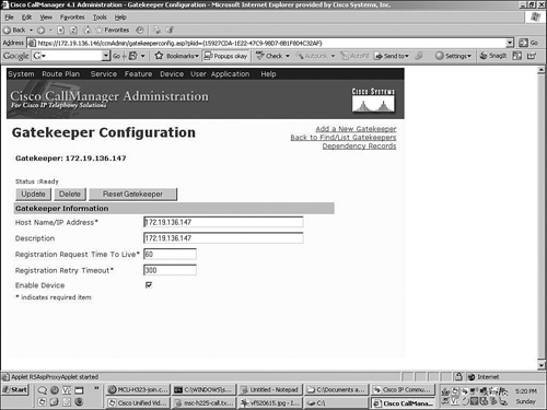
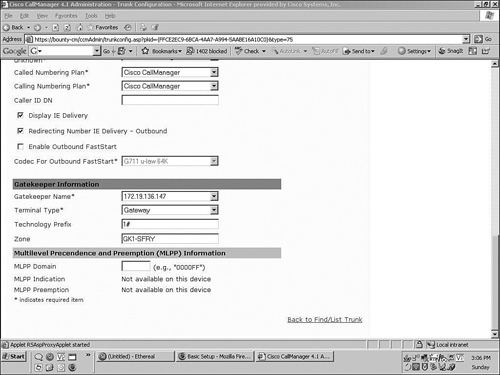
Cisco Unified CallManager (CUCM) supports H.323 gatekeepers, which may be configured using the CUCM configuration web page, as shown in Figure 6-14. In addition, a separate H.225 gatekeeper-controlled trunk definition is required, as shown in Figure 6-15.
Cisco Unified CallManager can also interwork with H.323 devices directly, without a gatekeeper. Any device that calls Cisco Unified CallManager resources directly (without a gatekeeper) must have its DNS name or IP address preconfigured in CallManager; otherwise, calls from the device are not accepted. H.323 gateways can access CallManager resources (for example, phone, PSTN gateways and trunks, and so on) by either having a specific H.323 gateway definition in CallManager, or by means of an H.225 gatekeeper controlled trunk.
Figure 6-14 shows a part of the web-based configuration page associated with the gatekeeper definition (as shown in the next section). Note that the technology prefix value configured in the CallManager trunk definition must match the value specified in the gw-type-prefix of the Cisco IOS-based gatekeeper.
Figure 6-15 shows a subsection of the CUCM configuration page for the gatekeeper-controlled trunk definition. The definitions correspond to the Cisco IOS gatekeeper configuration elements discussed in the next section.
Example 6-1 illustrates a sample H.323 gatekeeper configuration in a Cisco IOS router.
In this simple example, the network has only one gatekeeper. The configuration also shows the following:
The zone local statement identifies the local zone name and defines the domain name for endpoints registering with an e-mail address.
The zone prefix statement identifies local endpoints and in-zone calls.
The gw-type-prefix statement specifies the type prefix string (which must match the corresponding values in the Cisco CallManager trunk configuration).
The default-technology statement routes all calls to the CallManager trunk.
Gatekeeper configuration statements are configured under the gatekeeper sub-config mode.
The message sequence chart shown in Figure 6-16 illustrates two endpoints registering with a gatekeeper. The call flow shows endpoint A initiating a video call to endpoint B. In the diagram, both endpoints first register with the H.323 gatekeeper. After registration, Endpoint A initiates a call to Endpoint B using the gatekeeper direct endpoint signaling model.
MCUs can host multiple conferences simultaneously, and a single conference may have multiple video layouts or video presentation modes.
Predefined service prefix codes allow MCUs to associate network services and video layouts with specific patterns within E.164 access numbers. Users can call different numbers to access the same meeting, but with different bit rates and different video layouts. For example, a user could start a conference by dialing the following digit sequence:
Service prefix+Conference ID number
In Table 6-3, access number 851234 contains the service prefix for continuous presence conferencing with a 384-kbps rate (85) and a conference ID of 1234. The MCU establishes the conference 1234 as soon as the first call is connected.
Table 6-3. Sample Service Prefix Association with Conference Characteristics
Conference Type | Display Format | Service Prefix | Comments |
|---|---|---|---|
Voice activated, H.263, 384 kbps | 81 | The display shows the current active speaker. | |
Continuous presence, four endpoints, H.263, 768 kbps | 85 | The display shows the last four speakers. | |
Continuous presence, seven endpoints | 87 | The display shows up to seven endpoints. |
Other participants wanting the same screen layout as the first caller would join by dialing the same pattern, 851234.
If the participants want a different layout for the conference—perhaps voice-activated mode, for example—they dial a different service prefix specifying the desired presentation mode (for example, 811234).
Service prefixes can be used to describe other meeting attributes, such as bit rate, port reservation size, maximum number of participants, picture format (CIF, QCIF, and so on), the maximum frames sent per second, and whether data sharing is supported.
This chapter described the basics of H.323 signaling for audio and video and how it is used in conferencing systems. It explored the underlying protocols used for connection establishment and media negotiations and described some of the techniques, services, and components used for endpoint-to-endpoint communications.
International Telecommunication Union (ITU-T). H.225.0: Infrastructure of audiovisual services—Transmission multiplexing and synchronization. 2006.
International Telecommunication Union (ITU-T). H.241: Extended video procedures and control signals for H.300-series terminals. 2003.
International Telecommunication Union (ITU-T). H.245: Control protocol for multimedia communications. 2006.
Schulzrinne, H., S. Casner, R. Frederick, and V. Jacobson. IETF RFC 3550, RTP: A Transport Protocol for Real-Time Applications. 2003.