
This chapter covers the following topics:
Session Initiation Protocol (SIP) is a signaling protocol used for establishing media (audio, video, and instant messaging) sessions as part of audio/video conferencing, telephony, and other IP collaboration systems. SIP can also be used for presence and event notifications. SIP is defined in RFC 3261. This chapter addresses the following topics:
Overview of SIP, including different elements of the protocol and message structures.
Overview of Session Description Protocol (SDP) and its different parameters.
Introduction to conferencing support in SIP.
Ad hoc and scheduled conferencing operations, including specific aspects of SIP with respect to supporting video conferencing with call diagrams and examples. Technical notes are added to provide implementation-specific details.
Video codec extensions and RSVP support.
A SIP network consists of four types of elements:
User agent
Proxy server
Redirect server
Registrar
Each element performs specific functions and is independent of the others. These can be hosted on one server or run individually across the network. Each of these SIP elements is addressed using Uniform Resource Identifier (URI).
User agents are audio/video endpoints and call control servers in a SIP network. These endpoints have a client element, the user agent client (UAC), and a server element called the user agent server (UAS). A SIP user agent (UA) has both a client and a server. The client initiates the requests, and the server initiates the responses.
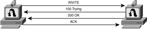
A SIP conference server is sometimes also referred to as Back-2-Back UA(B2BUA). It is a SIP element that has two UAs working back to back and thus can control the SIP dialogs as they go through it. Note that the endpoints are not considered B2BUAs.Figure 5-1 shows a SIP UA (video phone) initiating a SIP call to another user agent.
A proxy server receives SIP requests, determines where to send them, and passes them to the next server (the next server could be a user agent). The proxy server can provide functions such as authentication, authorization, routing of messages, security, and so on.
There are two types of proxy servers: stateful and stateless. A stateful proxy server stores incoming requests it receives, along with the responses it sends back and the outgoing requests it sends to other UAs and proxies. A stateless proxy server maintains no proxy information after it services a request. A stateful proxy server can keep track of active sessions, which allows it to load-balance the sessions across multiple SIP control servers.
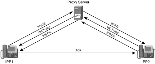
Figure 5-2 shows two UAs (IP phones) involved in a SIP session through a single proxy server. Both phones are registered with the proxy server. IPP1 sends a SIP INVITE message to the proxy. The proxy finds the location of the called party (IPP2) and forwards the INVITE. The proxy forwards all responses (100 Trying/200 OK) from IPP2 to the calling party (IPP1). In this example, the ACK response goes directly from IPP2 to IPP1. This can happen if the proxy does not insert a Record-Route SIP header in the SIP messages. Record-Route headers are explained in detail in the section “SIP Record Routing.”
A redirect server accepts a SIP request directed toward a particular UA and returns an alternate address to the initiating UA, thus providing forwarding services.
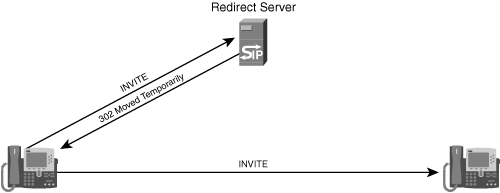
Figure 5-3 shows a SIP redirection of a call initiation.
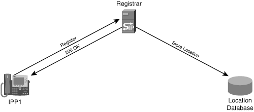
A registrar processes the registration requests from UACs. The registration request contains the current location (typically, IP addresses) of the UA. The registrar maintains a location database to associate SIP URIs to IP addresses. Note that the location could also be a different phone number or URL that is used by the UA for receiving calls. Registrars are usually colocated with the proxy servers.
Figure 5-4 shows an example of SIP registration from a UA to a registrar.
A transaction is defined by a request/response sequence: A SIP client sends requests to a SIP server, and the SIP server returns responses to the client. In Figure 5-5, a SIP UA sends an INVITE to another SIP UA and receives the responses (100 Trying/200 OK). The initial INVITE and the responses are considered to be part of one transaction. In general, ACK is not considered part of the transaction. Later SIP messages may include the disconnect request, known as the BYE message; these later messages are considered to be part of another transaction.
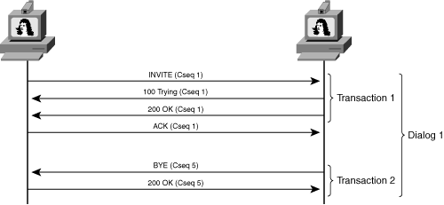
Each SIP message contains a 32-bit CSeq header value, which identifies each transaction.
As defined in RFC 3261, a dialog represents a peer-to-peer SIP relationship between two UAs. Dialogs facilitate proper sequencing and routing of messages between SIP endpoints.
Dialogs are uniquely identified using three fields:
The SIP header Call-ID
The SIP header From tag
The SIP header To tag
Messages that use the same values for these identifiers belong to the same dialog. In Figure 5-5, for example, transaction 1 and transaction 2 form a dialog.
SIP signaling comprises a series of requests (also called methods) and responses. A request consists of the following:
Request line (identifies the type of the method)
Headers
Message body (optional)
A SIP response message consists of the following:
Status line (identifies the status code of the request)
Headers
Message body (optional)
The following are the different types of SIP requests:
INVITE—. Invites an endpoint to join the call
BYE—. Terminates the dialog between two UAs
OPTIONS—. Requests information on the capabilities of the remote UA
MESSAGE—. Sends instant messages (not part of a dialog)
ACK—. Confirms that a UA has received a final response to an INVITE method
CANCEL—. Terminates the last pending request
INFO—. A mid-session method to pass the informational elements
PRACK—. Reliable provisional acknowledgment that confirms that a UA has received a provisional response, such as “180 Ringing”
UPDATE—. Updates the SIP session
SUBSCRIBE—. Requests notification of an event or a set of events from an UA
NOTIFY—. Sends an event notification to the subscribed SIP UA
REFER—. Indicates that the receiver should contact a third party using the contact information provided in the request
Example 5-1 shows a SIP request message.
Example 5-1. SIP Request Message
!The following line is the request line
INVITE sip:[email protected] SIP/2.0
!The following lines are the SIP headers
Via: SIP/2.0/UDP 172.27.14.4:5070;branch=8dJXAX9MDw

Max-Forwards: 70
To: <sip:[email protected]>
From: <sip:[email protected]>;tag=ds17aa9bd4
Call-ID: [email protected]
CSeq: 1 INVITE
Content-Length: 251
Content-Type: application/sdp

!The following lines are the SDP body


v=0
o=Sam 1549546120 0 IN IP4 10.10.10.26
s=-
c=IN IP4 10.10.10.26
t=0 0
m=audio 49220 RTP/AVP 0
a=rtpmap:0 PCMU/8000
The following sections describe the different components of the SIP request message.
The request line is the first line in the SIP request. It indicates the SIP method and the device to which this message is addressed. The last part of the request line is the version number, as indicated by SIP/2.0 in Example 5-1.
Example 5-1 shows the following headers:
Via—. The Via header indicates the transport to be used and carries the address and the port number to where the responses need to be sent. When this message passes through the SIP proxies, each proxy adds a Via header to the SIP request before forwarding it. This mechanism helps in detecting loops in routing.
The last part of the Via header is a branch parameter. It is used to identify the transaction created by the request and can also be used to distinguish between two versions of SIP RFC (RFC 2543 and RFC 3261). SIP devices that are compliant only with RFC 2543 do not insert the branch parameter into the Via header. RFC 2543 defines the basic SIP protocol, and RFC 3261 adds refinements to that. RFC 3261 obsoletes RFC 2543.
Max-Forwards—. The Max-Forwards header is used to detect loops in the forwarding path. Each proxy that received the SIP request decrements this counter by 1 before forwarding it. If a proxy receives a SIP request with a Max-Forwards value of 0, it sends an error back to the originator of the request.
To—. The To header identifies the recipient (or called party) device.
From—. The From header identifies the originator (or caller) of the request. The From header can optionally carry a display name (such as From: “Sam” <sip: [email protected]> tag=ds17aa9bd4). An anonymous request is indicated by the keyword Anonymous (for example, From: Anonymous <........>). The Tag parameter to used to identify the SIP dialog.
Call-ID—. The Call-ID header provides a globally unique identification to a SIP call.
CSeq—. The command sequence (CSeq) is an identifier that matches the request and responses of a transaction. It carries a value and the method name. The value can be an arbitrary number. The responses to the request should carry the same CSeq header as that of the request.
SIP responses are associated with a SIP request. Example 5-2 shows a typical response message.
Example 5-2. SIP Response Message
SIP/2.0 200 OK
Via: SIP/2.0/UDP
172.27.14.4:5070; branch=z9hG4bKhWn9PFlB2yaZbsvp36
From: <sip:[email protected]>;tag=ds15cee408
To: <sip:[email protected]>;tag=E2CE8-87E
Date: Fri, 01 Mar 2002 00:15:28 GMT
Call-ID: [email protected]
Server: Cisco-conferenceserver
CSeq: 1 INVITE
Allow: INVITE, OPTIONS, BYE, CANCEL, ACK, PRACK, UPDATE, REFER, SUBSCRIBE, NOTIFY, INFO,
REGISTER, PUBLISH
Contact: <sip:[email protected]:5060>
Reason: Q.850; cause=47
Content-Length: 0
The first line of the response contains the protocol version (SIP/2.0) and the status code (such as 200), along with a text description (such as OK). The status code is an integer from 100 to 699. RFC 3261 defines the following classes of responses:
1xx responses—. 1xx responses are called provisional or informational responses. A recipient of a SIP message can send a provisional response to indicate that the request was received and is being processed. RFC 3261 states that a provisional response may contain message bodies such as SDP or XML (Extensible Markup Language). Examples of provisional responses are “100 Trying,” “180 Ringing,” and “183 Session Progress.”
2xx responses—. A 2xx response is the last response message sent by the recipient for the associated request. Therefore, 2xx messages are always considered to be “final” messages. An example of a 2xx response is “200 OK.”
3xx responses—. 3xx responses give information about the user’s new location or an alternative service that the caller might use to satisfy the call. For example, if a proxy server receives an INVITE and cannot locate the recipient, it may send back a 3xx response to the sender requesting the caller to try a new address (and the new addresses is indicated in the header of the 3xx response). An example of a 3xx response is “301 Moved Permanently.”
4xx responses—. 4xx responses indicate failure and mean that the recipient could not process the request. The reason for the failure is indicated in the response itself. An example of a 4xx response is “400 Bad Request.”
5xx responses—. 5xx responses indicate failure due to an error encountered in the server. An example of a 5xx response is “500 Internal Server Error.”
6xx responses—. 6xx responses indicate that the server has definitive information about the recipient. For example, if the recipient does not want to take the call, the server or UA sends a “603 Decline.”
Table 5-1 summarizes the commonly used response codes.
The request to which a particular response belongs is identified using the CSeq header field. This header field contains the sequence number and the method of the corresponding request. In Example 5-2, it is an INVITE request.
When establishing a SIP call, the INVITE flows through one or more SIP proxies (if the caller does not know the address of the recipient) to the recipient. The subsequent SIP messages are sent back and forth between the caller and recipient directly, without the proxy getting involved in the signaling. However, in some cases, the proxy server may need to be present in the SIP signaling path to see all the messaging between the endpoints for the duration of the call. One example is the scenario in which the proxy is connected to a billing server and needs to report how long the call is active for billing purposes. The method by which a proxy indicates that it wants to stay in the path is called record routing.
Right before forwarding the initial INVITE, the proxy adds a Record-Route header that contains the URI of the proxy itself. This header makes sure that all subsequent requests belonging to the dialog are forwarded through the SIP elements that have record routed.
RFC 3265 extends the SIP specification, RFC 3261, to support a general mechanism allowing subscription to asynchronous events. Such events can include statistics, alarms, and so on.
The two types of event subscriptions are in-dialog and out-of-dialog. A subscription that uses the Call-ID of an existing dialog is an in-dialog subscription, whereas the out-of-dialog subscription carries a Call-ID that is not part of the existing ongoing dialogs. Figure 5-6 shows an example of out-of-dialog subscription.
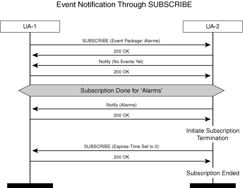
In Example 5-3, UA-1 is sending a SUBSCRIBE to UA-2 and subscribes for an event package called alarms. Event packages are implementation-dependent and are not defined in the specifications.
Example 5-3. SUBSCRIBE from UA-1 to UA-2
SUBSCRIBE sip:[email protected] SIP/2.0
Via: SIP/2.0/UDP 172.27.14.4:5070; branch=z9hG4bKhWn9PFlB2yaZbsvppn2Xlw~~34
Max-Forwards: 70
To: <sip:[email protected]>
From: <sip:[email protected]>;tag=ds7c86cbb5
Call-ID: 1bbd7b2:1009fdd37c1:[email protected]
CSeq: 1 SUBSCRIBE
Content-Length: 0
Contact: <sip:[email protected]:5070>
Content-Type:
Expires: 600
Event: alarms
A UA interested in event notification sends a SUBSCRIBE message to a SIP server (a SIP server could be just another SIP UA but provides additional services). The SUBSCRIBE message establishes a dialog, and the server immediately replies to this message using the 200 OK response. At this point, the dialog is established. The server sends a NOTIFY request to the user every time the event to which the user subscribed changes. NOTIFY messages are sent within the dialog established by the SUBSCRIBE. The NOTIFY messages usually carry an XML body that describes the event.
As part of the message exchange to establish a subscription, the server sends a NOTIFY message to the client with an indication of no events. Subscriptions have a limited life span (note the Expires header set in Example 5-3) and therefore must be periodically refreshed. A SUBSCRIBE with an Expires value of 0 indicates unsubscription.
SIP uses SDP (defined in RFC 2327), which defines a syntax to describe the media sessions. The SDP is carried as an application body (Content-Type: application/SDP) in the SIP messages. SDP consists of text messages using the ISO 10646 character set in UTF-8 encoding. A SDP consists of a session-level description (details that apply to the whole session and all media streams) and optionally several media-level descriptions (details that apply to a single media stream). Table 5-2 describes the session-level SDP parameters as defined by RFC 2327.
Table 5-2. Session-Level SDP Parameters
Field Type | Mandatory/Optional | Description | Example |
|---|---|---|---|
v= | Mandatory | Protocol version | v=0 |
o= | Mandatory | Owner/creator or session identifier | o=Sam 154954610 0 IN IP4 10.10.10.26 |
s= | Mandatory | Session name | s=conference call |
i= | Optional | Session information | i=conference call to Cisco Unified MeetingPlace Express |
Optional | URI of description | u=http://www.cisco.com/sdp | |
e= | Optional | E-mail address | |
p= | Optional | Phone number | p=+91-44-510623456 |
c= | Optional | Connection information; not required if it is included in the media level | c=IN IP4 10.10.10.22 |
b= | Optional | Bandwidth information; not required if it is included in the session level | b=CT:128 |
k= | Optional | Encryption key; not required if it is included in the media level | k=base64:7658339339 |
t= | Optional | Time the session is active | t=7776543 987656 |
Table 5-3 shows the syntax and examples of media-level SDP parameters.
Table 5-3. Media-Level SDP Parameters
Field Type | Mandatory/Optional | Description | Example |
|---|---|---|---|
m= | Mandatory | Media name and transport address | m=video RTP/AVP 31 |
i= | Optional | Media title | i=conference call to Cisco Unified MeetingPlace Express |
c= | Mandatory | Connection information; optional if it is included in the session level | c=IN IP4 10.10.10.22 |
b= | Mandatory | Bandwidth information; optional if it is included in the session level | b=CT:128 |
k= | Optional | Encryption key | k=base64:7658339339 |
a= | Optional | Attribute lines | a=rtpmap:0 PCMU/8000 |
Real-time Transport Protocol RTP specifies how media streams should be packetized. The headers of RTP packets include a payload type (ptype) that defines the type of data packet. RTP payload types can be static or dynamic. Static payload types are fully defined in the audio/video profile.
Payload numbers 0 through 96 are static payload types. In the following example, payload number 0 is a static payload type for PCMU (G.711 µ-law):
m=audio 49000 RTP/AVP 0
a=rtpmap:0 PCMU/8000
Dynamic payload types are defined during the session setup and are identified using payload numbers above 96. In the following example, the originator assigns 121 to identify codec G.722.1 during the SDP offer:
m=audio 49000 RTP/AVP 121
a=rtpmap:121 G7221/16000
There are two basic models for supporting multipoint conferencing through SIP:
A centralized model in which all the participants establish a two-way communication to a conference server. Conference servers could be cascaded, but this topology is transparent to the endpoint. As discussed in Chapter 2, “Conferencing System Design and Architecture,” IETF documents label this conference server the focus.
A distributed model in which the control plane (conference control and signaling) resides in the conference server, and the media processing is moved to separate devices. The following sections focus on the centralized model because it is widely developed and deployed.
A conference server controls the signaling plane of the conference, including creation, maintenance, and termination of the conference; adding and removing users; and managing Interactive Voice Response (IVR) sessions. The following sections discuss the basic elements of SIP conferencing, including the conference URI, early and delayed offer messages, and Dual Tone Multiple Frequency (DTMF) support.
A conference in a SIP framework is identified through a conference URI. The conference URI is the destination where all the SIP requests are sent and created/managed by the conference server. An example of the conference URI is sip:[email protected]. Users can enter these URIs manually in their SIP client to dial into the conference system. Alternatively, the conference system embeds this in a web link and sends the link to the user through e-mail or instant messenger. If the user dials in from the public switched telephone network (PSTN), the PSTN gateway determines the destination conference URI, typically by prompting the user to enter touch tones on the telephone pad. This prompting functionality is provided by the IVR system. The gateway is configured to either forward signaling to a conference URI or forward these DTMF tones to the conference server, which looks up the conference URI and instructs the gateway to forward the call.
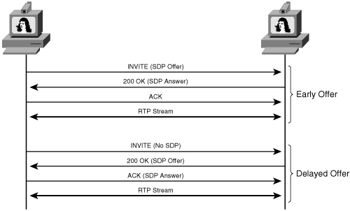
Endpoints establish connections on the media plane by first negotiating media properties such as codec types, packetization periods, media IP address/RTP port numbers, and so on. This information is transmitted with SIP messages using SDP. An endpoint may use two methods of exchanging SDP information:
Early offer—In the early offer, the endpoint sends the media SDP in the initial INVITE and receives an answer from the conference server.
Delayed offer—In a delayed offer, the endpoint sends an empty INVITE (INVITE with no SDP offer), receives an SDP offer from the conference server, and then sends back the final answer.
Figure 5-7 shows examples of early and delayed offers. A delayed offer is typically used by call control entities that do protocol translation (for example, an H.323 endpoint dialing into a call agent that has a SIP trunk to the conference server). In this case, the call agent may send a delayed offer INVITE to the conference server as soon as it receives an H.323 SETUP from the endpoint. The endpoint media capabilities are not known to the call agent until the H.245 OLC/OLC-ACK is done.
Endpoints that connect to a conference server via a PSTN gateway often must navigate through an IVR using DTMF tones, and therefore DTMF support in the endpoints and the conference server is important to the conferencing support. Endpoints can use three methods to send DTMF digits:
Voice-band
In-band
Out-of-band
Voice-band DTMF tones are modulated as actual tones in the media. Endpoints that dial into a PSTN gateway must play DTMF tones in the media stream so that the PSTN gateway can “hear” the tones. Endpoints connecting via an IP network send DTMF information in-band or out-of-band. RFC 2833 is a special way of sending DTMF in-band, and Key Press Markup Language (KPML) provides a way for the endpoints to send DTMF out-of-band.
RFC 2833 defines RTP payload types for carrying DTMF digits in-band in the media stream. This capability is specified as MIME type telephone-event in the SDP offer. Consider the following SDP offer, which is sent from a SIP endpoint to the conference server:
m=audio 19008 RTP/AVP 0 8 116
a=rtpmap:0 PCMU/8000
a=rtpmap:8 PCMA/8000
a=rtpmap:116 telephone-event/8000
The endpoint is indicating that it is capable of supporting RFC 2833 through the MIME type telephone-event (dynamic payload type 116). The conference server then can include the same in the SDP answer. When the user presses a digit, the endpoint sends an encoded RTP packet with the payload type of 116 (as negotiated in the preceding example).
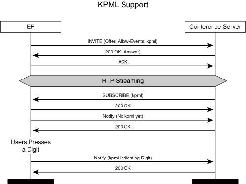
KPML is an out-of-band mechanism to collect DTMF digits. A KPML flow is established using SUBSCRIBE/NOTIFY. An endpoint can advertise that it supports KPML by including the string kpml in the Allow-Events header in the initial offer message. Similarly, the conference server may indicate the same in the response. The conference server then sends a SUBSCRIBE to the endpoint with the event package kpml. If the subscription succeeds, the digits are sent in the NOTIFY messages. Figure 5-8 shows the KPML subscription between an endpoint and the conference server.
Conferences are often referred to as either ad hoc or scheduled, based on the method by which they are invoked. Ad hoc conferences are created on-the-fly, without any prearranged scheduling. Scheduled conferences are “booked” in advance. The difference has to do with resource allocation: The conference server has limited resources to perform video and audio mixing. If a conference is scheduled in advance, the conference server is guaranteed to be able to allocate the required audio and video mixing resources. The signaling flow of an ad hoc audio and video conference is the same except for the presence of video media description in the SDP.
Because ad hoc conferences are created on-the-fly, the conference server cannot always guarantee that resources will be available at the time the conference is created. The conference server creates an ad hoc conference when the first participant connects to a URI associated with a conference that does not currently exist. Figure 5-9 shows an example of a conference started with an early offer.
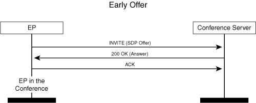
The following explains the flow illustrated in Figure 5-9:
The endpoint dials into the conference. Assume that this URI represents ad hoc conferences in the system. The endpoint sends the INVITE to the conference server with the SDP offer as follows:
v=0
o=san 1549546120 0 IN IP4 10.10.10.26
s=-
c=IN IP4 10.10.10.26
m=audio 49220 RTP/AVP 0 8
The conference server checks whether the mixer resources are available and creates a conference instance.
The conference server sends a 200 OK response with the SDP answer as follows:
v=0
o=CiscoSystemsSIP-GW-UserAgent 3402 403 IN IP4 10.10.10.2
s=SIP Call
c=IN IP4 10.10.10.54
m=audio 20000 RTP/AVP 0
Note that some SIP endpoints and conference servers may send an optional 100 TRYING message before sending 200 OK.
The endpoint completes the transaction by sending the final ACK.
The following notes provide some insight into the message flow from an implementation point of view:
Static payload types such as PCMU (G.711 µ-law)/PCMA (G.711 A-law) do not require rtpmap attributes in the SDP offer/answer. The rtpmap attribute is used to map the RTP payload type number to a media encoding name that identifies the payload format. An example is payload type number 34, which maps to payload format H.263.
The conference server can choose any payload type from the offer. Typically, the payload type is determined through a conference-wide policy. In the absence of such a policy, the conference server selects a payload type by giving preference to those appearing at the top of the list.
After the endpoint is in the conference, any change in the media property is communicated through the RE-INVITE message (also called mid-call INVITE). A RE-INVITE can be sent by either the conference server or the endpoint.
The default direction of the media stream is duplex (send and receive). If the endpoint just wants to receive the stream (examples include listen-only mode), it should include a=recvonly/a=sendonly in the SDP offer/answer.
A session-level attribute is applied to all the media in the SDP offer/answer. However, a media-level attribute (if present) overrides a session-level attribute.
The endpoint may add a session-expires header with a value in the initial INVITE to indicate how long this session is valid. The conference server can respond by adding the Session-Expires header back in the response. If the conference server does not support session expiry, it can respond in two ways:
The conference server can omit the Session-Expires header in the response.
The conference server can set a value of 0 in the Session-Expires header to indicate infinite session duration.
The endpoint starts an active session timer and sends a RE-INVITE or UPDATE message to extend the session upon each instance of session timer expiry. The absence of the Session-Expires header implies no expiration. Note that if the conference server does not set the Session-Expires header in response to a RE-INVITE or UPDATE, the endpoint should disable the session timer and assume an infinite session duration.
An endpoint can leave a conferencing session by sending a BYE. Alternatively, the administrator or conference chairman can disconnect a participant from a conference, in which case the conference server sends a BYE to the endpoint. The conference server deletes the ad hoc conference instance when the last endpoint drops out of the conference.
In some cases, the endpoint may initiate a delayed-offer INVITE. In that case, the conference server sends an SDP offer in the 200 OK response, and the endpoint sends the answer in the final ACK.
A video-enabled endpoint uses the same procedure to join a conference but offers additional parameters in the SDP offer to describe the properties of the video media stream.
Example 5-4 shows an SDP offer, in which endpoint A sends an INVITE to the conference server.
Example 5-4. SDP Offer from an Endpoint for Joining Ad Hoc Video Conference
v=0
o=san 1549546120 0 IN IP4 10.10.10.26
s=-
c=IN IP4 10.10.10.26
m=audio 49220 RTP/AVP 0 8
m=video 49222 RTP/AVP 109 34 96 31
a=rtpmap:109 H264/90000
a=fmtp:109 profile-level-id=42800c max-mbps=10000
a=rtpmap:34 H263/90000
a=rtpmap:96 H263-1998/90000
a=fmtp:96 SQCIF=1 QCIF=1 CIF=1 CIF4=2
a=rtpmap:31 H261/90000
a=fmtp:31 CIF=1 QCIF=1
The conference server chooses audio codec 0 (G.711µlaw) and video codec 34 (H.263) and responds with the SDP answer shown in Example 5-5.
The following sections describe the video SDP parameters that are sent in the SDP offer/answer.
The common video codecs used in video conferencing are H.261, H.263, and H.264. This section explains the syntax and semantics for describing parameters related to video codecs. Currently, no standard method exists to specify certain video-related parameters in the SDP offer/answer. These parameters include the following:
Video endpoints and conference servers use the a=fmtp attribute to carry codec-specific parameters. Note that SDP extensions for supporting video are still going through the standards process, and many endpoints and conference servers are using proprietary attributes in the SDP offer/answer. These variations might lead to interoperability issues between endpoints/conference systems.
SDP may contain ftmp parameters, which are media-level attributes that endpoints can use to define product-specific codec parameters not defined as part of the SDP specification. Some examples for H.261 are represented in the following syntax:
a = fmtp:<rtp payload type> <options>
<rtp payload type> = 31
<options>= "Size | Annex" where
 Size ="QCIF = MPI" or "CIF = MPI"
 MPI = 1 or 2
 Annex = D
Size indicates both a picture size and a frame rate. MPI stands for maximum picture interval. MPI=1 means that maximum (decodable) picture rate per second is about 30, and MPI=2 implies that the maximum picture rate per second is about 15. H.261 defines two resolutions: Common Interchange Format (CIF) and Quarter CIF (QCIF). Example 5-6 shows H.261 SDP syntax.
The H.263 draft defines three MIME types:
H.263
H.263-1998
H.263-2000
The attributes defined here can be used with any of these three MIME types:
a = fmtp:<rtp payload type> <options>
The <rtp payload type> for H.263 is a static payload type of 34. H.263-1998/H.263-2000 uses dynamic payload types.
The syntax for specifying the picture size is as follows:
<options>= size | annex
Size = "SQCIF=MPI" or "QCIF=MPI" or "CIF=MPI" or "CIF4=MPI" or "CIF16=MPI" or
"XMAX=xmax, ymax,mpi"
MPI = 1 or 2
Annex = F/J/T
Size indicates both the picture size and the MPI. H.263 defines multiple resolutions: SQCIF, QCIF, CIF, CIF4, CIF16, and CUSTOM. The annex values in the preceding example are just a representation rather than the comprehensive list of annexes that can be supported. The dimension of the custom picture size is defined by X and Y values. Example 5-7 shows a representation of H.263 codec parameters in the SDP offer.
The SDP offer in Example 5-7 indicates that the sender supports H.263-1998 at a clock rate of 90 kHz. The fmtp indicates that the sender hopes to receive QCIF picture size with a maximum packet interval (MPI) of 1. If QCIF is not possible, the sender prefers to receive SQCIF with an MPI of 1 followed by CIF with an MPI of 2. Most encoders support at least QCIF and CIF resolutions.
The optional parameters discussed in Example 5-7 are applicable for H.263-1998 only. For H.263-2000, these options (picture size, MPI) are specified through profiles and levels.Example 5-8 shows an SDP offer for H.263-2000. H.263-1998 does not support profiles and levels.
Note
There are three versions of H.263: H.263, H.263-1998, and H.263-2000. If no fmtp parameters are present in the SDP offer for an H.263 codec, it is safe to assume a form factor of QCIF at 30 frames per second (FPS). For H.263-2000, if no fmtp parameters are present, the default is profile=0 and level=10.
The sender can indicate the supported H.263 annexes in the fmtp attribute. H.263 annexes are enhancements to the core H.263 algorithm (H.263 baseline) that achieve improved performance and increased functionality. Additional supplemental information may also be included in the bitstream for enhanced display capability and external usage. In total, there are 16 negotiable annexes, named C to T, as explained in Appendix A. Example 5-9 shows an SDP offer that indicates the support of annexes F, J, and T.
H.264 uses a dynamic payload type. The encoding name in the rtpmap is H264, and the clock rate must be set to 90000. The optional H.264 parameters profile-level-id, max-mbps, max-dpb, max-br, parameters-sets, packetization-mode, interleaving-depth, deint-buf-size, init-buf-time, and max-dcon-diff, if any, must be included in the a=ftmp line. These parameters are expressed in MIME type strings.
H.264 media format is specified through the parameters profile-level-id and packetization-mode. The stream properties of H.264 streams are specified through the parameters sprop-parameter-sets, sprop-deint-buf-req, sprop-interleaving-depth, sprop-max-don-diff, and sprop-init-buf-time. The capability parameters are specified through max-mbps, max-fs, max-cpb, max-dpb, max-br, redundant-pic-cap, and max-rcd-nalu-size.
These parameters are used for declaring receiver capabilities and in general set the upper limit for what the receiver can support. Thus, a sender may select to set its encoder using lesser or equal values of these parameters.
The profile-level-id has three subcomponents:
Profile-idc (one octet)—. Indicates whether this entry represents an H.264 profile. A decimal value of 42 indicates that this entry is an H.264 profile. Baseline profile is used for video conferencing.
Constraint (one octet)—. The first 3 bits indicate whether this is a Main profile, Baseline profile, or Extended profile. The last 5 bits are reserved.
Level (one octet)—. Indicates the capability. Valid levels are 1, 1.1, 1.2, 1.3, 2, 2.1, 2.2, 3, 3.1, 3.2, 4, 4.1, 4.2, 5, and 5.1. For instance, level 3.0 is 4CIF at 25 FPS. Refer to the ITU-T H.264 codec specification for complete details on each of these levels.
Example 5-10 shows an SDP offer from a video endpoint.
In Example 5-10, a profile-level-id value of 428014 indicates the following:
42—. Represents an H.264 profile.
80(10100000)—. Baseline and Extended profiles are supported.
14(decimal 20)—. Level 2.0.
Example 5-11 shows an SDP offer from another SIP video endpoint. Note that max-mbps is an optional parameter. If present, this parameter should replace maxBR.
Bandwidth usage is specified with the attribute b: <modifier> <bandwidth value>.Modifier should be application-specific (AS), conference type (CT), or transport-independent application-specific (TIAS), as defined in RFC 3890. The AS bandwidth includes the bandwidth that the RTP data traffic will consume, including the lower layers, down to the IP layer. Therefore, the bandwidth is in most cases calculated by considering the entire IP packet, which includes RTP payload, RTP header, UDP header, and IP header. TIAS indicates the actual bandwidth in bits per second without the lower-layer overhead. If present at the session level, this entry indicates the bandwidth for all the media lines in the SDP offer/answer.
Although a session-level AS parameter should indicate the bandwidth needed for all the media lines in the SDP offer/answer (including audio), you might find that some of the endpoint implementations indicate just the video bandwidth needed.
Some endpoints may send a session-level AS parameter in addition to media-level TIAS to maintain backward compatibility with endpoints that do not support TIAS. In those cases, the session-level AS indicates the transport-independent rate for the call, and the TIAS parameter in the video session is the maximum bit rate that the endpoint can receive. Example 5-12 shows the presence of the bandwidth attribute in the SDP.
The b= parameter indicates that the endpoint expects to receive 320 kbps of video, which represents only the H.263 payload without the protocol headers. Upon receiving this SDP information, the conference server allocates CPU resources, and possibly network resources, to accommodate this bandwidth.
Advanced video endpoints may ask the conference server to send multiple video streams. The initial INVITE has one audio m-line (media line) and multiple video m-lines. Multiple video stream capability requires the ability to group the media lines so that the conference server knows which audio stream and video streams are tied together for lip-sync purposes. RFC 3388 defines some attributes (group) for the grouping. The syntax is as follows:
a=group:LS
a=mid:<identification tag>
Consider Example 5-13.
The sender of this SDP offer would like to receive three media streams: one audio stream (identified as mid:1) and two video streams (mid:2 and mid:3). Audio stream 1 and video stream 2 are grouped, which indicates that these need to be lip-synced. RFC 3388 mandates that all media streams have a prefix of mid, whether or not they are included in the group, which is why the third stream has a prefix of mid even though it is not included in the group.
Escalation is a process that allows a video-capable endpoint to join the conference in the audio-only mode and later establish a video stream. This process occurs in response to one of two scenarios:
End users begin a call in audio-only mode and then decide to add a video connection, either through inserting the camera or enabling video in their video phone.
An end user turns on a video camera while in an audio-only call, causing the endpoint to automatically establish a video connection. An escalation occurs through RE-INVITE from the endpoint, as illustrated in Figure 5-10.
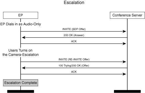
In the RE-INVITE, the endpoint uses the previous SDP offer/answer information but adds another m-line that includes the video properties. Note that the endpoint can take this opportunity to renegotiate the audio properties, but this type of renegotiation is uncommon.
In Example 5-14, an endpoint sends a RE-INVITE to the conference server to add video to the existing audio session.
In Example 5-15, the conference server responds with the SDP answer confirming that video will be streamed to the endpoint.
De-escalations are scenarios in which the endpoint tears down a video stream in an audio/video conference. The SIP flow for de-escalation is the same as that for escalation. The endpoint repeats the offer but removes the video information in the SDP offer section by setting the port number of the video stream to 0.
In Example 5-16, an endpoint that initially joined the conference in audio/video mode is now removing video from the session.
In Example 5-17, the conference server sends the answer SDP, acknowledging the removal of video for the endpoint.
The following describes the implementation details of the escalation and de-escalation scenarios:
If a SIP UA wants to reject a specific media line in the offer, it should set the RTP port m-line to 0 in the answer.
In de-escalation, the endpoint should set the RTP port number to 0 in the video m-line when sending the RE-INVITE.
In responding to the RE-INVITE offer, the SIP UA (either the conference server or endpoint) should keep the version number, defined in the o= line, the same as that of the previous answer if there is no change in the SDP offer. Incrementing the version for every offer/answer poses interoperability issues.
Escalation and de-escalation present resource-allocation challenges to the conference server. When the endpoint sends the initial INVITE to the conference server to set up an audio-only connection, there is no standard way to indicate in the SIP header or in the SDP offer that this endpoint is video-capable. Therefore, the conference server cannot know at this point whether it needs to allocate a video port to handle a possible escalation. There are a few possible solutions to address this issue:
Do not reserve video ports for endpoints that request an audio-only stream. As a result, the conference server will reject an escalation to video if video ports are not available.
Reserve the ports based on the conference policy. The conference system should let the administrator choose a resource management policy. Examples of such a policy include always reserving audio and video ports for all the ad hoc conferences.
Two primary video-specific media control operations need to be supported on video conferences:
Video fast update (VFU; also called fast video update[FVU])
Video freeze picture
An endpoint issues a VFU if its decoder requires an I-frame to continue decoding the video stream. When the encoder receives the VFU, it encodes the next frame as an I-frame. The decoder can request a full update or can ask the encoder to update only a part of the frame. The frame is divided into smaller parts, each called a group of blocks (GOB). GOBs are further subdivided into smaller units called macroblocks (MB). An endpoint can specify a video refresh for certain GOBs or MBs. However, endpoints typically request full frames.
Video freeze picture is sent from an encoder to a decoder. In case the encoder is aware of a change in the transmitted picture that would cause loss of synchronization, it requests the decoding side to freeze the picture—that is, to stop presenting the changes until a new stable image is encoded and transmitted. When an endpoint receives the video freeze picture request, it stops decoding the video until it receives a release signal that is part of the video bitstream. This release signal is sent by the encoder when it generates a new I-frame. A typical conferencing application of picture freeze occurs when the active speaker in a multipoint video conference changes. In this case, the conference server can send picture freeze to the endpoints and then send a release signal (the I-frame from the active speaker).
SIP currently has no standard method to support these operations, and competing proposals have emerged for adding these capabilities. However, most of the SIP endpoints and conference servers use the SIP INFO message with an XML document to communicate the codec control primitives. The XML body is carried in an INFO message and is sent by either the endpoint or the conference server. Example 5-18 shows an XML description of an I-frame request sent from a conference server to an endpoint.
Example 5-18. Video Fast Update Request
INFO sip:[email protected]:5060 SIP/2.0
Via: SIP/2.0/UDP 10.10.10.2:5060;branch=z9hG4bK123F
From: confserver <sip:[email protected]>;tag=1F144-1EEF
To: endpoint <sip:[email protected]>;tag=50a0a0a-13c4-418c31c9-5cb8215-d53
Date: Sun, 08 Jan 2006 00:02:08 GMT
Call-ID: [email protected]
User-Agent: Cisco-meetingplaceexpress
Max-Forwards: 70
Timestamp: 1014941016
CSeq: 101 INFO
Contact: <sip:[email protected]:5060>
Content-Type: application/media_control+xml
Content-Length: 168
<?xml version="1.0" encoding="utf-8"?>
<media_control>
    <vc_primitive>
      <to_encoder>
       <picture_fast_update>
       </picture_fast_update>
      </to_encoder>
    </vc_primitive>
</media_control>
Note that the Content-Type header is set to application/media_control+xml.
Even though using INFO for FVU is commonly supported among the video endpoints and conference server vendors, the solution is not approved by the IETF for a number of reasons:
It may incur too much overhead.
It may incur excessive delay.
It is not generic for video, because it does not work with other signaling protocols such as Real Time Streaming Protocol (RTSP).
IETF is currently defining a standard for codec control. It is not SIP-based but rather RTCP-based.
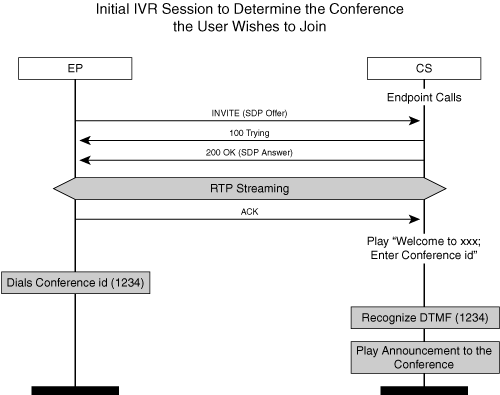
Scheduled conferences add complexity to the SIP flows. A SIP endpoint dialing into a scheduled conference takes the following steps:
Endpoints typically connect to an IVR before joining a conference. The IVR is either part of the conference server or tightly controlled by the conference server. The IVR terminates the endpoint signaling and authenticates the user. Authentication may include asking the user to enter the meeting ID of the conference.
After the user has been authenticated, the IVR typically prompts the user for a recorded name, generally with a message such as “At the tone, please say your name. When finished, press the pound key.” The IVR records the user’s name.
The conference server connects the endpoint to the conference and then issues an announcement, often including the recorded name of the new participant.
In addition, a conference server may supply a rich set of in-conference features for scheduled conferences, such as conference chairman controls. Chairman controls allow the meeting administrators to eject a participant from the meeting, mute participants, and so on.
The following sections discuss the SIP flows for different aspects of scheduled conferencing, such as IVR operation and in-conference features.
In the centralized conferencing model, the conference server is the central entity and terminates all the SIP signaling. After the media has been connected, the conference server performs IVR functionality, including DTMF collection, in the media plane, without further actions on the signaling plane, as shown in Figure 5-11.
In a distributed conferencing model, however, one central, logical conference server is composed of many individual servers. An endpoint might need to be moved from one physical server to another.
In Figure 5-12, endpoint EP dials into the entry IVR associated with the conference server, enters the meeting ID, and goes through the name-recording process. Centralized logic then moves the endpoint to another entity in the conference server that hosts the conference itself. Note that the name recording could be done after the endpoint moves to the conference.
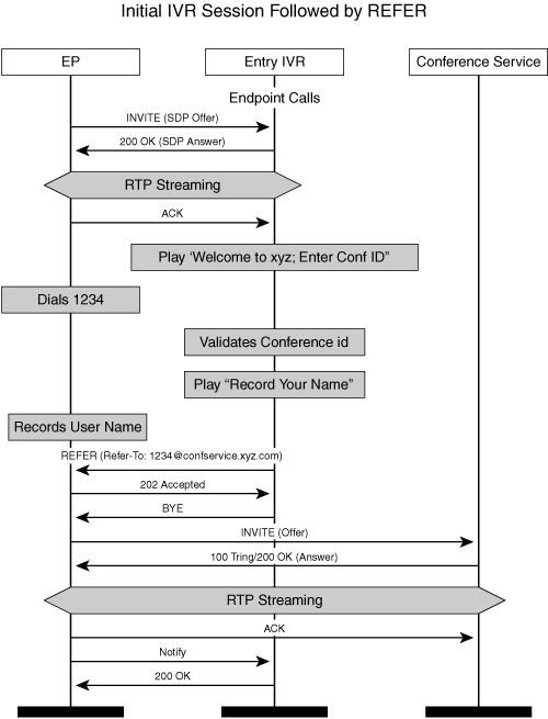
The entry IVR uses the REFER method to redirect the endpoint to the conference service component. The Refer-To header in the REFER provides the contact URI of the conference server.
The endpoint then sends an INVITE to that URI. The entry IVR sends a BYE to the endpoint immediately after the REFER message, because the INVITE dialog between the entry IVR and the endpoint is no longer meaningful.
Some implementations use INVITE with the Replaces header rather than REFER, as defined in RFC 3891 and as shown in Figure 5-13. The Replaces header is used to logically replace an existing SIP dialog with a new dialog.
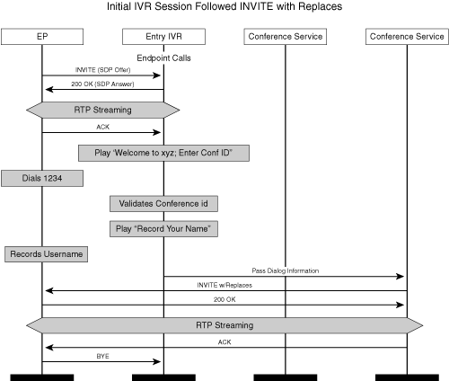
In this scenario, the destination conference server sends an INVITE with a Replaces header directly to the endpoint, while the endpoint still has a connection to the IVR. The IVR must provide the conference server with the information it may need from the IVR dialog. This information can be exchanged between the conference service and initial IVR through some out-of-band mechanism.
The rationale behind using INVITE with Replaces over REFER has to do with security considerations. The endpoint is authenticated by the conference system when it establishes a dialog relationship with the initial IVR. If the endpoint has to send another INVITE to the conference service (as a result of the REFER), it needs to be authenticated again by the conference service. With INVITE with Replaces, because the INVITE is initiated by the conference system, the conference system can reuse the credentials already established for the endpoint.
While in a conference, the endpoint can initiate a number of in-conference features. These features include roll call request, mute, unmute, hold/resume the call, transfer, and so on. The following sections address some of the most common features briefly.
A roll call as shown in Figure 5-14, asks the conference system to announce the names of all users in the conference. The announcement can be a public announcement, played to all participants in a conference, or it can be a private announcement, played to only a single participant. An end user who requests a private roll call enters the request by pressing a special digit (typically, the pound sign followed by a digit). The conference server detects the DTMF digit(s) and plays the names of all the callers in the system. During a private announcement, the conference server mutes the requesting endpoint while it plays the recorded names of participants. In Figure 5-14, the key sequence #4 notifies the conference server that the endpoint wants a roll call.
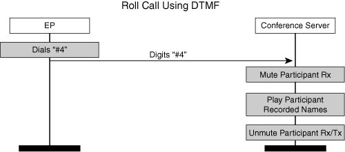
The conference servers get the DTMF digits and play the prerecorded participant names to the endpoint. Note that the conference server mutes and unmutes the receive side of the stream before playing the names.
The user presses the Hold button on the phone to place the conference call on hold. The endpoint initiates a RE-INVITE and puts the audio stream in sendonly mode, as shown in Figure 5-15.
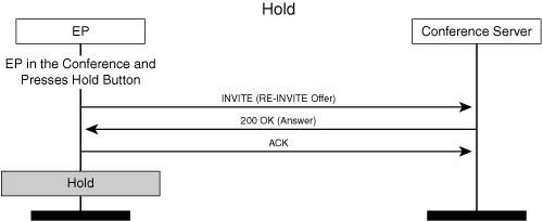
In the following SDP offer/answer exchange, note that the endpoint adds the attribute line a=sendonly, causing audio to flow only from the EP to the conference server. The conference server responds with a=recvonly.
The EP sends RE-INVITE with the offer shown in Example 5-19.
The conference server responds with the answer shown in Example 5-20.
When the user resumes the conference call, the endpoint sends a RE-INVITE again with the SDP offer a=sendrecv, and the conference server responds with the same.
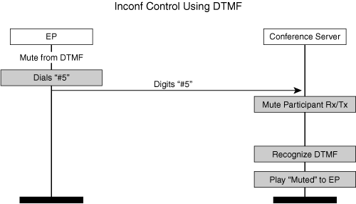
An endpoint can mute itself using one of two methods:
The endpoint can halt transmission of audio/video media packets to the conference server.
The endpoint can request that the conference server ignore packets from the endpoint.
An endpoint can instruct a conference server to ignore audio or video media packets by sending proper DTMF tones. In Figure 5-16, the key sequence #5 notifies the conference server that the endpoint wants to be muted. In response, the conference server plays an announcement to the endpoint and proceeds to mute the participant. Unmute works the same way as described for mute.
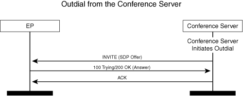
Some conference systems can dial out to a participant when the conference is about to start. The conference server obtains the participant outdial information from a directory through Lightweight Directory Access Protocol (LDAP) or from a presence server. Regardless, after the conference server knows the SIP URL of the participant, it initiates an INVITE with the SDP offer. In Figure 5-17 the conference server initiates outdial to a participant. The conference server sends an early offer in the INVITE and gets back an answer SDP in the “200 OK” response message.
Bandwidth reservation is important for the audio and video streams, and RFC 3312 provides the resource-reservation support in SIP. Audio streams should have a higher quality of service (QoS) than video streams because video tolerates delays better than audio. The endpoint may include a successful bandwidth reservation as a precondition of joining the conference. Or, the endpoint can make the reservation optional. Figure 5-18 shows a Resource Reservation Protocol (RSVP) conference flow where the endpoint indicates RSVP as a precondition in the initial INVITE.
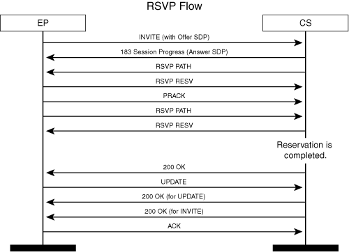
The following steps explain the flow shown in Figure 5-18:
The endpoint sends an INVITE and includes the following QoS attributes in the SDP offer:
m=audio 20000 RTP/AVP 0
c=IN IP4 10.10.10.2
a=curr:qos e2e none
a=des:qos mandatory e2e sendrecv
des is the desired status; it indicates that the session establishment should stop until this criterion is met.
curr is the current status of the network resources of the media stream.
In the preceding example, the SDP offer from the endpoint indicates that the current QoS status for the audio stream is none (no reservations are made), and the desired status is an end-to-end (indicated by e2e) reservation in both directions. This criterion is a mandatory precondition (indicated by the MIME string mandatory).
If the conference server supports RSVP, it knows when resources in its “send” direction (from the conference server to the endpoint) are available, because it receives RESV messages from the network. However, it does not know the status of the reservations in the other direction. The conference server sends a “183 session progress” message and requests confirmation by specifying conf:qos for resource reservations in its recv direction, as shown in the following example:
m=audio 30000 RTP/AVP 0
c=IN IP4 10.10.10.25
a=curr:qos e2e none
a=des:qos mandatory e2e sendrecv
a=conf:qos e2e recv
After sending the answer, the conference server starts reserving network resources for the media stream. When the endpoint receives this answer, it starts reserving network resources, too. The conference server sends PATH messages toward the endpoint, and the endpoint sends PATH messages toward the conference server.
Eventually, the conference server receives RESV messages confirming the reservation. However, it waits until resources in the other direction are reserved, too, because it did not receive any confirmation, and the preconditions still have not been met.
The endpoint sends a Provisional ACK (PRACK) message introduced in RFC 3262 in response to “183 session progress.” The PRACK message does not contain SDP offer/answer body.
When the endpoint receives RESV messages, it sends an updated offer (in UPDATE) to the conference server, as shown in the following example:
m=audio 20000 RTP/AVP 0
c=IN IP4 10.10.10.2
a=curr:qos e2e send
a=des:qos mandatory e2e sendrecv
The conference server responds with an answer SDP (“200 OK” in response to UPDATE) that contains the current status of the resource reservation (that is, sendrecv), as shown in the following example:
m=audio 30000 RTP/AVP 0
c=IN IP4 10.10.10.25
a=curr:qos e2e sendrecv
a=des:qos mandatory e2e sendrecv
At this point, preconditions are met, allowing session establishment to resume. The conference server returns a “200 OK” response.
The session establishment ends with the endpoint sending a final ACK to the conference server.
Any mid-session changes to the media properties, such as IP address changes, result in a RE-INVITE from either direction.
This chapter has reviewed the fundamentals of SIP and its implementation on the conferencing systems. SIP support for video conferencing is evolving but may gain dominance and provide industry-wide interoperability if the IETF can resolve several open issues discussed in this chapter.
Camarillo, G., G. Eriksson, and H. Schulzrinne. IETF RFC 3388, Grouping of Media Lines in the Session Description Protocol. December 2002.
Camarillo, G.(ed.), W. Marshall (ed.), and J. Rosenberg. IETF RFC 3312, Integration of Resource Management and Session Initiation Protocol. October 2002.
Handley, M., and V. Jacobson. IETF RFC 2327, SDP: Session Description Protocol. April 1998.
Handley, M., H. Schulzrinne, E. Schooler, and J. Rosenberg. IETF RFC 2543 (obsolete), SIP: Session Initiation Protocol. March 1999.
Mahy, R., B. Biggs, and R. Dean. IETF RFC 3891, The Session Initiation Protocol (SIP) “Replaces” Header. September 2004.
Roach, A. B., IETF RFC 3265, Session Initiation Protocol—Specific Event Notification. June 2002.
Rosenberg, J., and H. Schulzrinne. IETF RFC 3262, Reliability of Provisional Responses in Session Initiation Protocol. June 2002.
Rosenberg, J., H. Schulzrinne, G. Camarillo, A. Johnston, J. Peterson, R. Sparks, M. Handley, and E. Schooler. IETF RFC 3261, SIP: Session Initiation Protocol. June 2002.
Schulzrinne, H., and S. Petrack. IETF RFC 2429, RTP Payload Format for the 1998 Version of ITU-T Rec. H.263 Video (H.263+). October 1998.
Schulzrinne, H., and S. Petrack. IETF RFC 2833, RTP Payload for DTMF Digits, Telephony Tones and Telephony Signals. May 2000.
Westerlund, M. IETF RFC 3890, A Transport Independent Bandwidth Modifier for the Session Description Protocol. September 2004.