
CHAPTER 10
Balance of System: Batteries, Inverters, Controllers, and More
The stupidest thing we can do is put a turbine, large or small, in a place that has no wind. It’s also stupid to drill in Saudi Arabia when we have such great wind here.
–MORTEN ALBAEK, SENIOR VICE PRESIDENT FOR GLOBAL MARKETING OF VESTAS
You could have the sleekest turbine in the land on the highest tower, but if that’s all you’ve got, you aren’t getting any energy. You’ve also got to have what is often called the balance of system: bits of wire and various electronic do-dads that connect the turbine to your load and/or the grid. The balance of system (BOS) also has components that help ensure the whole system functions safely and smoothly.
This is also the part where we take a close look at batteries. You may have wondered why we haven’t spent a lot of time discussing batteries through most of this book. That’s because whether you ultimately decide to get batteries or not doesn’t have a big impact on many of the other topics we covered. You still need a good wind resource, a sturdy tower, permits, and a good generator, whether you store your energy on-site or not.
There are a few things to be aware of when it comes to batteries, however, and we’ll cover them in this chapter. We’ll also examine the other devices you need to condition and distribute your hard-won energy, including charge controllers, inverters, disconnects, breakers, wire, and more (Figure 10-1).

FIGURE 10-1 A National Renewable Energy Laboratory technician inspects the Trace inverter (left) and charge controller (upper right) of an off-grid solar/wind hybrid system. Warren Gretz/DOE/NREL.
Inverters
The first question you may have when it comes to inverters is whether you even need one. If you are reading this as an e-book on a handheld device or notebook, you are technically using direct current (DC) power. If you are reading this book under house or office lighting, most likely you are using alternating current (AC). Most of our stuff runs on AC. True, some applications do operate solely on DC power, such as many recreational vehicles (RVs), most boats, and some isolated cabins and water-pumping stations.
There has actually been a fierce debate, spanning more than a century, about which type of power is better, DC or AC. We won’t get into the details here, although it’s worth pointing out that many people, from electrical engineers to do-it-yourselfers, have strong opinions about their relative merits and best applications. Thomas Edison sacrificed cats, dogs, and even a circus elephant to the (literally) fiery debate. For the most part, most of the appliances and electronics we want to run take AC power out of the box, even if many of them have an adapter that converts incoming line power into DC to actually run the device (computers are like that).
Most small-scale power generators produce DC (although with wind, it’s even a bit more complicated than that). So if you want to run something like an AC-powered gadget from a DC car battery in a mobile home, you need a device that will convert DC to AC—an inverter. If you want to go the other way, AC to DC, you don’t use an inverter. You use another electrical component called a rectifier. Rectifiers are usually based on diodes, and most wind turbines have them.
Because wind is a variable phenomenon, it doesn’t drive the rotor at a constant RPM. This means the system’s alternator doesn’t spin at a regular rate. So instead of producing an even source of current, as the grid does, it tends to produce AC that constantly varies in voltage and frequency. This type of current is often called wild AC, or three-phase AC, and it isn’t very usable. So most wind systems send this current into a rectifier, which then converts it to DC.
In batteryless systems, the voltage coming from the turbine rectifier could be anywhere from 100 to 600 volts DC. In a battery-based system, it is most likely at 48 volts DC, or 12 volts DC for a small system. (Older systems sometimes produced 24 volts DC, but that is getting rare.)
We mentioned in Chapter 8 that it is possible to make a wind turbine with a DC generator, although that is quite rare, since they tend to be more expensive and larger than alternators. Either way, you end up with DC power that you can use directly if you are driving a water pump or wiring up a wilderness cabin. But most folks take the next step to AC.
If you wanted to make a simple inverter, all you need is a mechanical switch that reverses the flow of current. Reversing a battery on a simple loop circuit would do the trick, for example (all batteries work on DC). If you were to flip that battery or that switch 60 times a second, you would approximate the frequency of the AC current in the North American grid. In fact, the simplest types of inverters are like that, and the output of current they produce would show up on a graph as square waves, with each peak or trough indicating the direction of current.
Square wave inverters are still on the market, and they are the least expensive, though a lot of devices won’t run on them, they waste power, and they can be hard on equipment. Better is a sine wave inverter, which produces a more gradual switching of current. Sine wave inverters cost more, but they more closely replicate the grid, so they don’t wear out your toys.
In between a square wave inverter and a sine wave inverter is something called a modified sine wave inverter. In these devices, the output goes to zero in between switching from positive to negative, instead of flipping abruptly from one direction to the other. The energy is still a bit “rough,” but it is usable in many devices, though sometimes not in some sensitive equipment like laser printers. Prices are often (~$0.10USD/Watt), compared to (~$0.50 to $1.00USD/Watt) for sine wave inverters (also called pure sine wave inverters).
Ian Woofenden cautions consumers to beware of marketing claims that boast “true sine wave,” since that isn’t a regulated term. Sine wave inverters are solidstate devices, so they can’t ever produce perfectly smooth patterns of electricity, the way power companies can with their moving magnets. Instead, sine wave inverters use a device called an H-bridge, which is really a series of switches, much like our thought experiment earlier with the battery switching directions (Figure 10-2). The more finely tuned the switching structure in the inverter, the closer the resulting waveform will be to an actual sine wave. And the more expensive the inverter will be.

FIGURE 10-2 A Xantrex SW Plus Inverter/Charger, a sine wave inverter and battery charger combination unit. Xantrex Technology/DOE/NREL.
Woofenden suggests that if you are really “nitpicky,” look for the lowest total harmonic distortion, preferably less than 3 percent, which indicates how far off the wave is from the ideal.
If you only need to power up some basic stuff, like lights, power tools, and kitchen appliances, you may be fine with a basic modified sine-wave inverter, though be aware that most loads will draw more power than when connected to the grid. However, you may not be able to run dimmer switches, variable-speed drills, sewing machines, battery chargers, or anything else where the current varies. That’s because the switches on such devices are used to looking for the sine wave pattern of grid power to control operation, and they have trouble “reading” the abrupt zero point from a modified sine inverter.
With a modified sine inverter, you also may feel a bit like you entered the Twilight Zone, because fluorescent lights and stereos may buzz and plug-in clocks may have trouble keeping time. The lower the total harmonic distortion, the more everything will behave like it is on grid power, although you’ll pay more for the inverter.
Of course, it’s also worth remembering that all electrical components “lose” a little of your precious energy as waste heat. But good equipment loses less, retaining 90 percent or more.
For many people shopping for wind energy systems these days, there isn’t a lot of choice when it comes to inverters. More and more manufacturers and dealers are selling their products as package deals, with inverters that are prematched to the system’s other components.

Tech Stuff Even so, it’s important to know a few things about inverters. One thing you may notice if you start researching them is references to different types of internal technologies. Inverters may use newer high-frequency transformers, conventional low-frequency transformers, or no transformers at all. A transformer isn’t just a robot toy; in electrical engineering it is a device that steps up or down voltage, usually through coils of wire that induce a field in each other. In our experience, when it comes to inverters, these technical differences are not make-or-break features, but if you want to geek out on inverters, more power to you.
Although an inverter’s primary job is to convert DC to AC, it may also serve some other functions in your system. For instance, they can aid in charging, start generators, and provide data logging.
In general, there are three main areas to consider when selecting an inverter:
• Input voltage You will likely be considering ranges of 100 to 600 volts DC for batteryless systems or 12, 24, or 48 volts DC for battery-based systems. Clearly, you need to check with your turbine’s manufacturer to see what type of voltage it will be producing. You don’t want to fry your brand-new inverter the first time the wind blows!
• Output voltage This is typically 120 or 240 volts AC, but may also be 208, 277, or 480 VAC.
• Wattage The peak capacity the inverter can handle, or the maximum amount of energy you can use or sell back to the grid at any moment. In a grid-tied system, the peak wattage of the inverter needs to be at or above the absolute peak power of the turbine.
While the terminology and content will vary by manufacturer, inverter datasheets also often include the following information:
• Peak efficiency This value indicates the highest efficiency the inverter can achieve. Most grid-tied inverters on the market have peak efficiencies of 94 percent or greater. No system is going to have 100 percent, because some energy is always going to get lost in the shuffle, usually as waste heat. There usually isn’t much difference between inverters when it comes to peak efficiencies, so this isn’t so much a comparison tool as it is an awareness tool. If you are counting watts, the efficiency tells you how much you need to subtract from the input to the output. For example, if your inverter has an efficiency of 95 percent, and you need 5,000 watts out of it, you’ll have to put in 5,263 watts.
• CEC weighted efficiency You may have noticed the word “peak” in the preceding entry, and that might have left you feeling there is still guesswork in the system. The CEC weighted efficiency attempts to close that gap, and is published by the California Energy Commission (CEC) on its GoSolar website. It’s an average efficiency that better represents actual operation.
• Peak power tracking voltage This represents the DC voltage range in which the inverter’s maximum-point power tracker will operate.
• Start voltage This value indicates the minimum DC voltage that is required for the inverter to start working.
• NEMA rating The National Electrical Manufacturers Association rating indicates the level of protection the device has against water intrusion. Most inverters are NEMA 3R, which means outdoor rated for most situations.
• P56 rating (rest of the world) Similar to the NEMA, indicating suitability for use outdoors.
Now let’s take a look at the two main types of inverters:
• Grid-tied inverters
• Off-grid or stand-alone inverters
Note that you have to make the decision about which type of inverter you want at the onset. Inverters come as either-or deals, and you can’t simply switch over or “upgrade” an inverter to the other type.
Grid-Tied Inverters
A grid-tied inverter (or grid-interactive or grid synchronous inverter) is used to convert direct current into alternating current and feed it into the grid (Figure 10-3). This is done to either offset electricity costs or supplement residential or commercial power usage.

FIGURE 10-3 In a grid-tied system without batteries, current flows from the turbine through a charge controller, into an inverter, and then through a meter and out to the grid. WindEnergy7.com.
Grid-interactive inverters are the most efficient way to produce renewable energy, because the least amount of energy is wasted. They send energy to the grid, and you are credited for each watt, per your net-metering agreement. You don’t have to worry about any energy that is dissipated over time in batteries. However, grid-tie inverters must have an active connection to the grid to function. If the grid is down, they cannot be used at all. They have an auto-shutoff feature that disables them, so that way any line workers won’t get shocked by your system.
Before a grid-tied inverter can send power to the grid, it must synchronize its frequency to 60 hertz in North America. It does this through its built-in components, including a local oscillator. The inverter must also synchronize the voltage to the grid, which is usually at 240 or 120 VAC (volts AC). Typical modern grid-tied inverters have a fixed unity power factor, which means output voltage and current are closely lined up, with a phase angle within one degree of the grid. The inverter typically has a built-in computer that senses the grid’s waveform and matches it. Therefore, a grid-tied inverter is always a sine wave inverter.
In the United States, grid-tied inverters must also meet specific technical provisions in the National Electric Code. Most other countries have similar rules.
Off-Grid Inverters
Off-grid inverters, of course, work without the presence of a grid. They take the energy you produce with a wind turbine and convert it into a form that is useable in your home, business, cabin, or boat. In that case, you have a choice of square, modified sine, or sine wave models, and we discussed the advantages and disadvantages of each earlier.
We also mentioned that battery-based wind generators typically produce 12, 24, or 48 VDC. That means off-grid inverters have to step up the voltage to something more commonly useful, usually either 120 or 240 VAC.
In most cases, when you have an off-grid situation, you are going to want energy storage, for when the wind isn’t blowing strong or the sun isn’t shining. To get storage, you have to have batteries, as well as a battery-based inverter.
With a battery-based system, the battery voltage you choose will be the inverter’s input, while the output will be the standard load you want to run. You have to choose the inverter’s wattage, although note that it should always be equal to or larger than the turbine’s peak output.
One thing to keep in mind is that the larger an inverter is, the more power it will eat up during operation. That could be anywhere from 2 to 20 watts continuously. So when it comes to sizing your inverter, we hope you followed our advice in Chapter 4 and assessed how much energy your place uses.
You probably don’t need to get an inverter that can run absolutely everything you own at once, but you do want something that can handle what you use during the course of a typical day. Otherwise, you may end up with angry family members, constantly bickering over who gets to use the hair dryer or the Xbox. Note that many devices use more energy at startup than during operation, although the good news is that most off-grid inverters are designed to be able to handle brief surges.
Rex A. Ewing wrote in Countryside magazine that he runs his house, and a “voracious 1.5 horsepower well pump,” with a Xantrex SW 4024 sine-wave inverter, offering 4,000 watts of continuous output and a 120/240-volt transformer. Ewing explained that his guest cabin “does nicely with a Xantrex DR 1524 modified sine-wave inverter, capable of 1,500 continuous watts, while the tools in my small workshop work handily with an inexpensive Aims 2,500-watt modified sine-wave unit.” He concluded, “Three different inverters, for three different jobs. It’s just a matter of knowing what each one will, and won’t, do.”
You’ll also have to determine if you want an inverter that can charge the batteries through the use of a gas-powered generator. Almost everyone living off the grid has a supplemental fuel generator, usually diesel or gasoline fired. Being able to recharge your batteries with that generator can boost flexibility.
In fact, many high-end inverters have multistage battery charging capabilities built right in, assuming the job of a charge controller (see later). However, such a combination unit does add cost and weight. During normal operation, the inverter will send power to the loads that are running at the time and then charge the batteries. High-end inverters also usually come with sophisticated programs for monitoring and controlling the system from your computer.
Grid-Tied with Battery Backup
This type of system tends to confuse people, who often assume that it combines the best of both worlds, without realizing that it also has drawbacks. If you have batteries at all, you need to have an inverter that can work with them. That means a battery-based inverter, even if you are also hooked up to the grid (Figure 10-4).

FIGURE 10-4 In a grid-tied system with batteries, current flows from the turbine through a charge controller, then into the batteries, a dump load, or an inverter.
This type of system will keep working even if the grid goes down, which is good, but it also means you have the extra expense of batteries, plus the effort to maintain them, and you lose power over time that is sent to your batteries but not used.
We discuss the relative merits of this choice in greater detail in the section on batteries that follows.
Batteries
If you live off-grid, you are going to want batteries, unless you have very restricted applications (Figure 10-5). Otherwise, your lights are going to flicker and your computer is going to shut off every time there’s a lull in the wind. That does not sound like fun. If you live on the grid, you may think you want batteries for backup during a blackout. But read this first.

FIGURE 10-5 This bank of 20 Trojan L-16 deep-cycle batteries is mounted in a vented box inside a Colorado home, which is powered by a 2.88 kW solar system and two AIR 403 wind turbines on tilt-up towers. Warren Gretz/DOE/NREL.
Five Things You Need to Know About Batteries
1. Batteries need more maintenance than most other components in a wind system.
2. The bigger the battery bank, the higher the cost and the lower the efficiency.
3. Battery banks are primarily recommended only for off-grid living.
4. Grid-connected users are required to use special inverters that prevent energy stored in batteries from going into the public utility during a blackout.
5. Public utilities traditionally frown on battery banks.
In short, batteries are fairly expensive, they take up a lot of space, and they require more maintenance then you might think. But we’ll break these issues down.
What you need for wind energy systems are what are called deep-cycle batteries, which are designed for repeated discharging of a significant amount of their stored energy. These batteries are also called traction batteries. What you don’t want is starting batteries, like common car batteries, which aren’t meant to be heavily discharged.
To keep their weight down and to increase their surface area, car batteries are made with many thin lead plates, with each one having a porous texture like a sponge. They are designed for heavy discharge lasting just a few seconds, followed by a long period of slow recharge. That’s perfect for a car starter. But deep cycling such batteries causes the sponge to break down, often to the point of failure in just 30 to 150 deep cycles.
That is not what you want for a wind system. Better are deep-cycle batteries, which have thick plates made of solid lead. This means they have less surface area, so they can’t release as much energy as rapidly. Instead, they are designed for hours of heavy discharge each day, followed by relatively fast recharge in only a few hours.
In your travels through battery stores, online or in person, you will likely encounter marine batteries. As the name implies, these products are intended for boats, although they have a wide range of quality and design. In general, marine batteries tend to be intermediate between starting and deep-cycle batteries, though a few brands like Rolls-Surrette and Concorde are built like “true” deep cycle. In an intermediate marine battery, the plates are midway between thin and thick, and may or may not have a sponge texture.
Unfortunately, there aren’t really batteries designed specifically for small wind systems, because the industry is too small and niche to support robust manufacturing of them. Instead, most batteries used with turbines were originally designed for electric golf carts, forklifts, or floor scrubbers.
People new to wind energy often ask if the batteries are sophisticated lithiumion types, like the ones found in laptops and cell phones. As of this writing, we aren’t aware of any folks who are using those powerful batteries, because they are quite expensive. For comparison’s sake, the lithium-ion batteries on board hybrid cars cost thousands of dollars. The price for lithium-ion has been decreasing steadily, so that may change in the near future.
It’s true that some people use NiCad batteries with solar or wind systems, but they tend to be expensive as well (less so than lithium). NiCad batteries can be difficult to dispose of because of the toxic cadmium inside. In general, most experts suggest you avoid them for wind energy, unless you have to work in extremely cold temperatures, where they perform better than alternatives.
Types of Batteries
Today, most wind systems rely on tried-and-true lead-acid batteries, like the big one in your car, except formulated for deep cycling instead of starting. Lead-acid batteries come in two general types, described in the following sections.
Flooded Batteries
In a flooded battery, the cells are open, and you have to add distilled water occasionally (Figure 10-6). The liquid inside a battery is called electrolyte. It’s not Gatorade; it’s a mix of sulfuric acid and water. The level tends to go down over time in flooded batteries, due to slow evaporation and during a process called battery gassing. You never want the liquid level to fall below the plates, because they will be permanently damaged through contact with air.

FIGURE 10-6 These flooded lead-acid batteries have hydrocaps, which are supposed to recombine the oxygen and hydrogen released while charging, reducing water loss up to 90 percent. Byron Stafford/DOE/NREL.
You have to check the levels of these batteries every few months, and if they are low, add distilled water. If you are the kind of person who can’t keep a houseplant alive, even a cactus, that might be a problem for you.
The pros keep a temperature-adjusted hydrometer handy, and they routinely test the specific gravity of the electrolyte. You should do this when the battery is fully charged. Don’t use it for several hours, and then discharge it for a few minutes to remove the surface charge. Then you can insert the hydrometer and take a reading. If the specific gravity is below 1.225, you could have sulfation happening.
Sulfation is a chemical reaction that deposits sulfates on the lead plates. That’s a problem, because the sulfates act like insulators and diminish the battery’s ability to store and release charge. At an advanced stage, sulfation will ruin the battery, and the only remedy is replacement. Sulfation can occur when batteries are less than 100 percent charged, so for this reason, experts usually suggest keeping lead-acid batteries “full” at all times.
Hydrometer readings shouldn’t vary by more than 0.5 between cells. A fully charged battery should generally be at 1.265, while a battery at 75 percent will be at 1.225, 50 percent will be at 1.190, 25 percent will be 1.155, and discharged will be 1.120.
Advantages of flooded batteries:
• Cheaper
• Last longer
Disadvantages of flooded batteries:
• Must be periodically topped off with distilled water
• Require occasional cleaning
• Vent flammable hydrogen and oxygen gas when charging (and potentially toxic hydrogen sulfide gas)

Hazard Given the last point, it’s critical to make sure the space that holds your batteries is well ventilated. If flammable or toxic battery gases are allowed to build up, it can spell trouble or even death.
Sealed Batteries
Sealed batteries have their cells completely closed off, so you can’t add more liquid, even if you wanted to. The good news is that sealed batteries don’t require as much maintenance, but the bad news is they cost more and don’t last as long. They also require more careful charging, so you have to make sure your charge controller is properly set up. If you overcharge a sealed battery, it will force out some moisture, and there’s no way to replace that. (As you know, they are sealed.)
Sealed batteries come in a few different stripes. Some are gel (also called gelled), which are made with silica gel (Figure 10-7). In that case, the battery acid is bound up inside the gel, sort of like a jelly doughnut. An advantage of gel batteries is that it is impossible to spill acid, even if the case were to break in half. However, gel batteries must be charged more gradually, at a slower rate and lower voltage, to avoid damage.

FIGURE 10-7 A typical valve-regulated gel lead acid battery. Koyosonic.
A newer technology, AGM (absorbed glass mat) batteries use fiber separators to absorb the electrolyte, and are generally more durable. These batteries also won’t spill acid, since it is bound up in the mat. They are more rugged than gel batteries and can be charged faster.
All gel batteries and most AGM ones are “valve regulated,” which means that a tiny valve keeps a slight positive pressure. However, AGM batteries vent very little, since they are recombinant, meaning oxygen and hydrogen recombine inside the battery. AGMs also have a low self-discharge rate, typically from 1 to 3 percent per month. This means they will hold their charge for a long time. AGMs are also quite resistant to freezing, since they have very little liquid inside.
The main disadvantage of AGMs is their price: they tend to cost two to three times as much as standard flooded batteries of the same capacity.
Advantages of sealed batteries:
• Less maintenance (don’t have to put water in them)
• Vent less flammable and toxic gas
Disadvantages of sealed batteries:
• Cost more
• Don’t last as long
Basic Battery Chemistry
Tech Stuff At this point, we thought it would be helpful to provide a brief primer on how batteries actually work. Batteries are electrochemical devices that store and release electrical energy through chemical reactions.
When a lead-acid battery is discharged, the electrolyte (sulfuric acid) and some of the lead on the plate react, producing water, lead sulfate, and current. Thus, the chemical equation for discharge is: PbO2 Pb 2H2SO4 -->PbSO4 2H2O + Electrical energy.
During charging, the equation would run in reverse, producing lead, sulfuric acid, and heat, plus hydrogen gas. In flooded batteries, the hydrogen gas vents to the outside (unless it is partially caught and recirculated via a hydrocap). In sealed ones, it recombines with oxygen.
Sometimes, if the plates are damaged or the electrolyte levels get too low, hydrogen sulfide gas can form. That’s the gas that smells like rotten eggs, and it is poisonous at high concentrations. In sealed batteries, the gas shouldn’t leak to the outside, but it is still possible through small cracks. So having well-ventilated batteries is critical (Figure 10-8).

FIGURE 10-8 Dave Corbus from the National Wind Technology Center inspects a bank of Trojan L-16 deep-cycle batteries that are connected to a small turbine. Warren Gretz/DOE/NREL.
Battery Ratings: Amp-Hours
We introduced the concept of amp-hour (Ah or AH) in Chapter 3: one amp-hour is one amp of charge flowing through a wire for one hour. So amp-hours are amps times hours. This is how all deep-cycle batteries are rated. So if you have something that pulls 20 amps and you use it for 20 minutes, then the amp-hours used would be 20 (amps) × 0.333 (hours), or 6.67 Ah.
Most batteries are rated at 20 hours. This means the amp-hours put out by a battery are measured over a period of 20 hours, down to the point of total discharge. By the way, batteries have 10.5 volts at full discharge, due to their internal chemistries. Many manufacturers also list amp-hour ratings for other periods, such as 6 hours or 100 hours.
In case you are wondering, a battery cycle is usually defined as one complete discharge and recharge cycle. If you need a technical standard, it is often considered discharging from 100 percent to 20 percent, and then back to 100 percent. However, there are often other ratings.
Cost of Batteries
As we mentioned, batteries aren’t cheap. One general estimation is to add $2 or more per watt to the cost of a system when you add batteries. That means that batteries for a 10 kW system can cost as much as $20,000 if you want to store all the energy. This would include the cells, the basic extra equipment needed to charge them, and the storage location.
Individual batteries cost $150 to $300 each for a heavy-duty, 12-volt, 220 amp-hour, deep-cycle product. Larger-capacity batteries, those with higher amp-hour ratings, cost more. A typical 110-volt, 220 amp-hour battery bank, with a charge controller, costs at least $2,000.

Power Up! And remember, the larger your battery bank, the less efficient the system, because the more energy you “lose” over time through self-discharge and internal resistance.
Energy Loss from Internal Resistance
Everything in life has its price, and using batteries is no exception. A rough observation is that if you use 1,000 watts from a battery, it may take 1,050 or 1,250 watts to fully recharge it. Much of the energy loss during charging or discharging is due to what’s called internal resistance, which usually manifests itself as heat. The lower the internal resistance, the less energy gets wasted as heat, so the more efficient the battery.
Typical lead-acid batteries are 85 to 95 percent efficient, while deep-cycle AGMs can approach 98 percent. NiCads are around 65 percent. However, note that the slower the charge or discharge, the less energy is wasted as heat, so efficiency is higher. A battery rated at 180 amp-hours for 6 hours might do 220 Ah at 20 hours or 260 Ah at 48 hours.
Battery Longevity
Now that you have some idea how much batteries cost, chances are good that you want to make the ones you have last as long as possible. It turns out that there are many factors that affect battery longevity, including charging patterns, temperature, maintenance, and so on. Less deep and less aggressive charging and discharging cycles tend to make for longer-lasting batteries.
Although deep-cycle batteries are designed for heavy discharging, running them all the way down repeatedly does decrease their lifespan. This is why many battery manufacturers suggest trying not to discharge below 50 percent.
According to Northern Arizona Wind & Sun, if a battery is discharged to 50 percent every day, it will last about twice as long as if it is cycled to 80 percent depth of discharge (DOD). If it is cycled only to 10 percent DOD, it will last about five times as long as if it were cycled to 50 percent. Although that last number sounds impressive, you are also buying batteries to use them, so 50 percent is often considered a reasonable compromise. (Note that DOD is the opposite of how much energy is left in the cells. A DOD of 80 percent means you have a battery that is 20 percent “full.” See more on proper battery charging later.)
By the way, don’t think that you can just set up your batteries and forget about them. Like plants, they need regular feeding, because inactivity can be harmful to their internal chemistries. Ian Woofenden suggests making sure your batteries are fully charged up at least a couple of times a week (Figure 10-9). Never buy a battery to store for later use. Either use it or, at a minimum, put it on a slow and steady trickle charge.

FIGURE 10-9 This Colorado home is powered by a hybrid solar and wind system, plus the battery bank in Figure 10-5. Warren Gretz/DOE/NREL.
As far as temperature, even though battery capacity increases with higher temperatures, battery life decreases. This explains why your grandma kept her batteries in the refrigerator, next to the meatloaf. So if you can keep your batteries in a cool space, they will last longer.
You can also increase the longevity of your batteries with regular maintenance. If you have flooded batteries that need refilling, stay on top of it. Never let the plates get exposed to the air.
Speaking of plates, it turns out that the thickness of the positive plate is one of the more important factors when it comes to battery longevity. The positive plate gets eaten away over time, so the thicker the plate, the longer it tends to last. Incidentally, the negative plate expands a bit during discharging. This is actually why most batteries have separators that can take some compression, such as paper or glass mat.
According to Northern Arizona Wind & Sun, car-starting batteries have plates around 0.040 inch (4/100 inch) thick, forklift batteries have plates more than a quarter-inch” thick, and golf cart batteries have plates around 0.07 to 0.11 inch thick. Concorde AGM’s are 0.115 inch, the Rolls-Surrette L-16 type (CH460) is 0.150 inch, the U.S. Battery and Trojan L-16 types are 0.090 inch, and the Crown L-16HC size is 0.22 inch thick.
Northern Arizona Wind & Sun has provided a rough guide of minimum and maximum lifespans for the following battery types, when used in deep cycle service, such as would be found with a wind electric system:
• Starting batteries: 3 to 12 months
• Marine batteries: 1 to 6 years
• Golf cart batteries: 2 to 7 years
• AGM deep cycle: 4 to 7 years
• Gel deep cycle: 2 to 5 years
• Deep cycle (L-16 type, etc.): 4 to 8 years
• Rolls-Surrette premium deep cycle: 7 to 15 years
• Industrial deep cycle (Crown and Rolls 4KS series): 10 to 20+ years
• Telephone (float): 2 to 20 years. These are usually special-purpose “float service,” but often appear on the surplus market as “deep cycle.” They can vary considerably, depending on age, usage, care, and type.
• NiFe (alkaline): 5 to 35 years
• NiCad: 1 to 20 years
Sizing Your Battery Bank
Regardless of what type of batteries you use, it’s critical to size your battery bank—your collection of batteries—properly. You’re not going to want a massive bank, because that is going to get quite pricey when you have to replace them every few years. You also don’t want to waste too much energy over time through seep and inefficiency.
It turns out that sizing a battery bank can be pretty tricky (Figure 10-10). Your first impulse may be that you’d like to have enough batteries to run everything in your house for at least a week without generating any power. That’s a nice idea, and we hate to smash your dreams, but that’s not very realistic. It would just take too many batteries to be practical. You will also run into problems if it takes you too long to replenish your battery bank from normal operation of your wind generator. Since you lose some of the energy you put in batteries, you don’t want to end up on a downward spiral of always trying to fill the things up and never quite catching up.

FIGURE 10-10 Sizing a battery bank can be tricky; batteries are expensive and require maintenance, and the more you have, the more energy you lose through self-discharge. Warren Gretz/DOE/NREL.
More typically, you’ll probably want to size your system to run critical loads for a couple of days. After that, if the winds don’t pick up or the sun doesn’t shine on your solar panels, you’re going to have to crank up the old diesel generator.
Batteries come in many different sizes, and may be given a wide range of codes that refer to their physical heft or intended use. For example, we often see GC for golf cart batteries or FS for floor scrubbing batteries. As we mentioned, there aren’t any WS batteries for wind systems. Even so, the actual battery size and designation isn’t what’s usually critical. It’s more important to map out the specifications and make sure the battery matches your system and your objectives.
So, there are a few things to consider when thinking about battery sizing. All lead-acid batteries supply around 2.14 volts per cell when fully charged. Since standard 12-volt batteries are made with six cells, that means the total would be 12.6 to 12.8 V. In addition, a typical 6-volt golf cart battery can store about 1 kilowatt-hour of useful energy:
6 volt × 220 amp-hr × 80% discharge = 1,056 watt-hours
To give you an idea of what that means, that’s roughly enough juice to power two 50-watt light bulbs for ten hours.
2 × 50 × 10 = 1,000 watt-hours
As you can see, unless you live like a monk, you will probably need more than one battery. Remember that batteries are heavy (around 65 pounds for that golf cart number), so you need some space. You also need good ventilation, and preferably a floor that could withstand the occasional splash of acid.
Although 220 amp-hour golf cart batteries are often used, some others prefer larger “L-16” deep-cycle batteries with ratings of 350 amp-hours. The good news is that you probably have considerable choice, although note that a lot of discount batteries don’t hold up very well.
Another thing to keep in mind is that battery capacity (how many amp-hours it can hold) goes down as temperature goes down. Compared to the standard rating at room temperature, going down to –22 degrees F would tend to drop the capacity in amp-hours by 50 percent. At freezing, capacity is typically reduced by around 20 percent. At 122 degrees F, battery capacity would tend to be 12 percent higher.
We bring this up because it can affect the sizing of your system, particularly if you live in places with extreme temperatures. You may also need to think about insulating your battery bank. The good news is the bank itself is a considerable thermal mass, and usually takes some time to adjust to air temperature.
Writing in Backwoods Home Magazine, Jeffrey Yago, a licensed professional engineer, gives more insight into precise sizing of a battery bank. Yago suggests the example of needing to power a 12-volt DC lighting system, consisting of four fluorescent fixtures, in an off-grid cabin. Each light is rated at 36 watts and draws 3 amps (36 watt/12 volt = 3 amp). If everything is lit up at once, that gives a lighting load of 12 amps (4 lights × 3 amps).
Yago reasonably suggests that you might use these lights from 5:00 P.M. until 11:00 P.M. each night, or six hours per day. That means your battery system must supply 72 amp-hours (12 amps × 6 hours) of energy each day, ignoring efficiency losses.
If we have a 350 amp-hour battery, it will deliver 175 amp-hours (350 × 0.50) before needing recharging if discharged to 50 percent, the standard recommended level. That means the lights can be used for two days (175 amp-hr/72 amp-hr) before needing recharging.
Yago also points out that there’s a problem with his example, namely that the 6-volt battery isn’t producing enough voltage to run the 12-volt lights. He explains that if we simply wired two of the batteries in series, we would end up with 12 volts, but only the same capacity of battery, because multiple batteries wired in series have the same amp-hour capacity as each individual battery. Wiring batteries in parallel gives multiples of the amp-hour capacity, but does not increase the voltage.
The solutions to this electrical mindbender are to increase the system voltage to 12, 24, or 48 volts, and/or to wire the batteries in series-parallel. Outlining exactly how to do the wiring is beyond the scope of this book, but the good news is there are many plans online. Better yet, your installer can show you the ropes, or hire a licensed electrician.
Yago points out that there are a few things to watch out for with battery wiring. He notes that failure of individual cells can drag the system down, so it’s a good idea to be diligent about maintenance and monitoring. Yago also says every wire that passes through the positive terminal of a battery should go through a protective fuse—and one rated for DC. He notes that DC fuses have to be more robust than AC fuses.
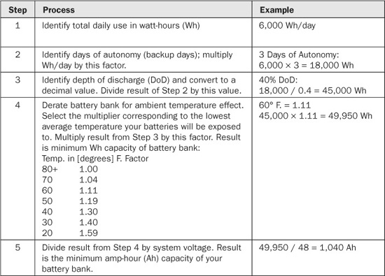
To bring it all together, Table 10-1 is a handy chart to help you size your battery bank, written by Chris Brown for www.btekenergy.com.
TABLE 10-1 How to Size a Battery Bank
Organization of Battery Banks
Most people put their battery bank in a basement, garage, or storage building. Don’t put batteries directly on a cold floor, because that will decrease their capacity (although it would increase their lifespan). Try to keep clutter from encroaching on their space, and if you need to wipe off a battery, use only water (Figure 10-11). Never use any kind of solvent around them.
People often build enclosures for their batteries to keep things tidy. It’s a good idea to control the ventilation, too, which should exit to outdoor air. One popular solution is to build a wood frame, line it with plywood, and then add PVC piping for ventilation. It’s a good idea to cover the wood with several coats of fire-and acid-resistant paint.

FIGURE 10-11 Inverters and battery bank at Manzanita Indian Reservation near Boulevard, California. Warren Gretz/DOE/NREL.
Hazard Keep open flames away from battery banks. During certain stages of their operation, they may release flammable hydrogen and oxygen.
INTERCONNECT
Building a Useful Small Wind Turbine for $140
Michael Davis is a small wind enthusiast who shows how a hobby can have some tangible benefits (Figure 10-12). A few years ago, the amateur astronomer bought a piece of property in the wilderness of Arizona that was perfect for stargazing, but far removed from any grid service. On the plus side for Davis, this meant freedom from the light pollution that obscures the heavens. But he still wanted a little power to run a few devices, like his laptop and camera chargers.

FIGURE 10-12 An amateur astronomer and tinkerer, Michael Davis built a small wind system for his remote Arizona property for just $140 in parts. It powers his computer, cell phone, air mattress pump and other small devices. Michael Davis www.mdpub.com/Wind_Turbine.
Davis answered our questions via email, and he has posted extensive information (and videos) about his project on his website, www.mdpub.com/. From scrap and off-the-shelf parts, Davis has built his own telescope, solar panels, and even a jet engine. On his remote Arizona property, Davis installed some of his solar panels, built a wood gasifier, and in 2006 he erected a homebrew wind system, which he wrote, “cost hardly anything.”
Davis told us that his little system has held up very well, and said he was surprised that “even such a crude design could work very well.” He wrote, “If you have some fabricating skills and some electronic know-how, you can build one too.” Interestingly, Davis said his website has become “insanely popular,” taxing its server with more than a million visits a year. He said he gets “dozens of requests for help every day,” mostly from folks who want advice in building their own wind turbines.
Davis began building his turbine by doing research online, and seeing what has worked for other handy folks. He noticed that some people use permanent magnet DC motors as generators, instead of the more customary AC alternators. He suggests that what can work well is a motor that is rated for high DC voltage (more than 12 V), low RPMs and high current. Such motors were historically used in computer tape drives. In his view, car alternators aren’t a good choice because “they have to spin at very high speed to produce useful amounts of power.” For his project, Davis scored an old Ametek tape drive motor on Ebay for $26, which he says works great.
Davis cut his blades out of ABS plastic drainage pipe, which he sanded down to a smooth shape to give an airfoil. He bolted the blades to a metal hub, and fastened the motor to a piece of 2x4, adding a bit of sheet metal for a tail (to keep the turbine facing into the wind). For the tower, Davis selected 1¼-inch diameter steel EMT electrical conduit, which he got from a big box store. He used pipe fittings at each end, and a slightly thinner, 10-inch pipe serves as the connector and yaw bearing for the top. For the base, Davis used a piece of plywood, with holes for staking into the ground.
Davis ran wires from the generator through the center of the conduit, to his controller, which he built himself based on schematics he found online. He then connected lead acid batteries (Davis suggests always connecting to batteries first, then to the wind turbine, to avoid damaging the electronics; similarly, unhook the turbine first if you are taking it down). For a dump load, Davis wired together several high-wattage, 2-Ohm resistors. He also added a 120V inverter.
On site, Davis is able to easily raise and lower the 10-foot tower, which is supported by four guy lines (at first nylon rope, later steel cable). On most stays on his remote property, Davis’ small wind turbine produces all the juice he can use for his laptop, air mattress pump and electric razor, plus charging of his camera and cell phone batteries. When he brings his pop-up camper along, he has power for a light bulb and vacuum cleaner (though not quite enough for his girlfriend’s hair dryer).
Davis gets all this convenience for a total cost of $140 in materials for his wind system, plus some of his time and a little ingenuity. Recently, he added a small home-built solar panel. His systems are cheap and easily portable, and they show that if you have modest electrical needs, a very small turbine may be a good solution (Figure 10-13).

FIGURE 10-13 Davis made his small wind system from off-the-shelf parts, and it meets his needs on his off-grid property. Michael Davis www.mdpub.com/Wind_Turbine.
Davis added, “If I had it to do over again, knowing what I know now, I would have made the tail larger, and used steel guy wires. Maybe I would have looked for a generator with higher output.”
He told us, “Many of my neighbors have small wind turbines. They are more popular than urban people may realize.” However, he warned, “It won’t power your whole house. Small wind turbines are a great supplement to a solar power system. If you are going to live off-grid, you are going to have to seriously change your lifestyle and drastically reduce your power consumption.”
Charge Controllers
If you have batteries, you need to have a charge controller, or you will quickly ruin the batteries by under-or overcharging from your wind generator. Even systems that are grid-tied but also have batteries need a charge controller, primarily for when the grid is down. Otherwise, the inverter effectively acts as a charge controller, sending only as much power to the batteries as needed to keep them full.
Fortunately, charge controllers aren’t particularly expensive, and are often in the $100-to-$200 range. The primary job of a wind turbine charge controller is to constantly monitor the state of the batteries. It does this by watching the voltage coming out of the battery bank and looking for what are called set points.
When battery voltage approaches a maximum set point (called the float voltage), the controller turns on the dump load (also called a shunt or a diversion load). Most charge controllers have adjustable set points, which are often chosen in the 13.2 V to 15.2 V range for 12 V charging systems, or 26.4 V to 30.4 V in 24 V charging schemes.
When the battery voltage falls back below another threshold (typically 0.2 V to 0.5 V below the float voltage), the dump load is switched off, and juice starts flowing into the battery bank again.
As we stated in Chapter 1, the purpose of the shunt is to dissipate excess energy without overcharging the batteries or leaving the turbine unloaded. If you overcharge the batteries, their lifespan will be reduced, and if you unload the turbine, it could dangerously freewheel. As mentioned previously, the most common dump load is an electrical heating element placed in water or open to the air. Some small systems use high-wattage car headlight bulbs, and some clever folks rig up electric sawmills or other devices that can put the excess energy to use doing work.
In a grid-tied, batteryless system you don’t need a dump load, because you can always send juice to the grid. If the grid goes down, your system will stop. If you have a grid-tied system with batteries, you do need a dump load for when your batteries are full but the grid is down.
A charge controller also usually has a blocking diode in it that stops reverse current from seeping out of your batteries toward your wind generator. Many controllers also provide automatic battery equalization (see later) and built-in data logging. Most controllers have a built-in heat sink to dissipate heat that builds up during operation, particularly from relays (Figure 10-14). Sometimes the heat sink is a noticeable series of metal fins, although in some models it looks more subtle.

FIGURE 10-14 Part of the balance of system inside the Colorado home from Figure 10-8, showing two stacked inverters (left) and charge controllers (upper right). Note the fin heat sinks across the tops of the latter. Warren Gretz/DOE/NREL.
Will Solar Charge Controllers Work for Wind Systems?
In general, you do not want to use a charge controller that is designed for solar panels with a wind system. That’s because a wind turbine must always be connected to a load, unlike solar panels, which are more forgiving. If solar panels start to produce too much juice, the controller can just short-circuit them, and nothing will get damaged. If you just cut off a wind turbine, it won’t have a load, and it could start to freewheel out of control.
It is true that many new charge controllers are marketed as working well with both small solar and wind systems. Such units must be able to transfer current to a shunt.
Many of these controllers come with two switchable modes: shunt mode or diversion mode. In shunt mode, the dump load is powered directly from the battery. This will draw down the energy stored in the battery. You might choose to do this if the batteries got overcharged, for example. In diversion mode, the battery retains its charge, while the power coming out of the generator goes to the dump load.
Note that although they can be designed without them, some solar systems are set up with dump loads. One reason to do this is to avoid going through a switching transistor in a regular solar charge controller, since those devices rob a bit of precious energy.
AC and DC Controllers
If you are like Michael Davis (see the Interconnect section on page 351) and your wind turbine has a DC generator, you can use a DC charge controller. However, as stated previously, most wind turbines don’t have DC motors. Most have alternators that produce wild AC, also called three-phase AC. Before this can be used it is usually rectified to DC, then used to charge batteries or sent to an inverter.
Many charge controllers have built-in three-phase bridge rectifiers, which convert the wild AC into DC. Some wind turbines have built-in rectifiers, so in that case you may not need this feature, and may be able to get along with a DC controller. In some setups, separate rectifiers are put in place before the charge controller. The important thing is to know how all the parts of your system are going to interconnect and how they will work together. The good news is there are options out there.
The Effects of Temperature Changes
We mentioned previously that temperature affects batteries, so if your system is subject to wide changes in temperature, you may need to make some adjustments. Battery-charging voltage varies from about 2.74 volts per cell at –40°C to 2.3 volts per cell at 50°C. Since there are six cells in each battery, this means correct charging voltage drops by about 0.15 V for each 5°C rise in ambient temperature.
One strategy is to protect your batteries from temperature extremes by placing them in a conditioned space (Figure 10-15). You can also add insulation around batteries.

FIGURE 10-15 A technician tests the 230-volt VRLA batteries of a 50 kW system at the National Wind Technology Center. Warren Gretz/DOE/NREL.
Also note that some charge controllers come with temperature compensation (such as Morningstar). One thing to remember is that this will only be effective if the controller is subject to the same temperatures as the batteries. If one is inside while the other is outside, that might be a problem.
Protecting Your Batteries: Proper Charging and Equalization
Fortunately, lead-acid batteries aren’t subject to the memory effect, unlike nickel-based technology. Over time, nickel batteries will lose capacity unless they are fully discharged at least once a month.
However, as we mentioned, lead-acid batteries are subject to sulfation, a chemical reaction that deposits sulfates on the lead plates. This diminishes the battery’s capabilities, and could ruin it. Since sulfation can occur when batteries are less than 100 percent charged, experts usually suggest keeping lead-acid batteries “full” at all times.
This is another job for your charge controller. When set up properly, it will continuously float charge the batteries to compensate for gradual self-discharge and keep them at 100 percent. Of course, if you have a grid-connected system with batteries, this means you are also continuously using a bit of your energy just to keep your batteries topped off, even if you rarely use them.
In addition to float charge, there are two other general stages of most battery charging, plus a few related concepts.
• Bulk Charging Starting from an empty battery, bulk charging is usually the first step. In this process, current is sent into the battery at the fastest rate it can safely accept, typically at 10.5 to 15 volts (assuming a 12 V system). Bulk charging normally ends when the battery voltage hits 80 to 90 percent of the full charge level. Note that with gel batteries, all charging is usually done at two-tenths of a volt less than with flooded batteries in order to reduce water loss and damage.
• Absorption Charging During absorption charging, voltage remains constant and current gradually tapers off, while the battery’s internal resistance rises. During this stage voltages are typically around 14.2 to 15.5 volts.
• Float Charging When the battery reaches a full charge, the process should stop, because overcharging a battery will damage it. However, batteries lose charge over time through self-discharge, and that’s where float charging comes in. Float charging “tops off” the battery as needed, typically at a lower level of 12.8 to 13.2 volts. This is also called a maintenance or trickle charge.
The controller may use pulse width modulation (PWM), in which it senses tiny voltage drops in the battery, and then compensates by sending short pulses of charge. It is called “pulse width” because the width of the pulses varies, from a few microseconds to several seconds. For long-term float charging of batteries that are rarely used, some experts recommend keeping the float voltage around 13.02 to 13.20 volts.
• Float Charging vs. Trickle Charging Strictly speaking, there is a difference between trickle charging and float charging. A trickle charger sends a low level of current continuously, regardless of the state of the battery. So leaving a trickle charger connected to your battery indefinitely will overcharge it. A float charger, however, includes circuitry that monitors the battery voltage. When it senses that the battery is full, it stops charging. This means float charging can be left on indefinitely, as long as it is set up properly. As mentioned previously, you may need to make an adjustment for temperature changes (many controllers have programs that make this easy), because the correct float voltage drops by about 0.15 V for a 5°C rise in ambient temperature for a 12-volt system.
• Equalization To extend the life of your flooded batteries, you should apply an equalizing charge every 10 to 40 days. An equalization charge is about 10 percent higher than normal full charge voltage, and it is applied for 2 to 16 hours. The goal is to ensure that all the cells are equally charged and that the gas bubbles mix the electrolyte. Otherwise, what happens over time is that the liquid in the battery can become “stratified,” often with stronger solution on top and more dilute solution on the bottom. This can degrade your battery over time. AGM and gelled batteries require less frequent equalizations, though some experts say doing it two to four times a year is a good idea. Do check your manufacturer’s guidelines.
• C/8, C/20, and C/4 If you start researching batteries, you may see references to maximum recommended charging rates. For flooded batteries, experts recommend that you avoid charging at more than the C/8 rate, which is the battery capacity at the 20-hour rate divided by 8. For example, a 220 Ah battery would have a C/8 rate of 26 amps. Gel batteries should be charged at no more than the C/20 rate, or 5 percent of their amp-hour capacity. Otherwise, the gel can form cavities that never heal. AGM batteries can be charged quicker, to C/4. Of course, check with your battery manufacturer for specific specs.
• Maximum Power Point Tracking (MPPT) This popular controller feature adjusts the operating voltage of a wind generator at different speeds to maximize energy output.
Most of the time your system is operating, the controller will be in float charging mode (and MPPT if you have it). Of course, there are going to be times when it runs in bulk charge and absorption mode, such as when it’s time to replenish batteries that have been spent. It’s also a good idea to get into the habit of regular equalization sessions.
Building a Charge Controller from Scratch
Amateur astronomer and electronics tinkerer Michael Davis built his own charge controller from spare parts to work with the 12-volt small wind system he built for just $140 (see the Interconnect section on page 351). He mounted the parts of his controller on a wood board, along with a terminal block for connections and his dump load, which is a series of high-wattage resistors (Figure 10-16).

FIGURE 10-16 Michael Davis built a charge controller for his turbine from spare parts (center bottom). The rectangles on the top are high-wattage resistors, his dump load. Below and to the left of that is the main fuse, and the cube to the right is an automotive relay for switching the circuit. Michael Davis www.mdpub.com/Wind_Turbine.
Davis built the main circuit of the controller based on a free schematic he found online, assembling it on a standard perfboard about the size of a paperback novel. Davis wired it to a 40 amp SPDT automotive relay, which routes the turbine power either to the batteries or to his shunt.
Davis set the circuitry up so that if the battery voltage drops below 11.9 volts, the controller switches the turbine power to charge the battery. If the battery voltage rises to 14.8 volts, the controller switches to his dump load resistors.
Davis writes that he chose 11.9V and 14.8V “based on advice from lots of different websites on the subject of properly charging lead-acid batteries.” He explained that many people recommended slightly different voltages, so he averaged them. When the battery voltage is between 11.9V and 14.8V, the system can be switched between either charging or dumping, thanks to a couple of buttons he added. He also added LED lights to indicate when the system is charging or dumping.
How to Connect or Unhook a Controller
It’s critical to remember that a wind turbine must remain loaded at all times so it doesn’t spin too rapidly and get damaged. So it always needs to be connected to the grid or your battery bank. When you are working with a charge controller, always connect it to your battery bank first, then to the wind turbine. If you do it the other way around, the wild electrical swings coming from the wind generator won’t be smoothed out by the load. The controller could start to behave erratically or even get damaged.
Similarly, always disconnect the wind turbine first and the battery last when you are taking things apart.
Voltage Clamp
Particularly with large turbines, some systems are designed with an additional regulator before the charge controller. This voltage clamp can be inside the turbine itself or a separate piece of equipment, though it is often provided with the turbine. The job of the clamp is to smooth out the voltage to a level that’s safe for the equipment in the system.
Many charge controllers also effectively function as a voltage clamp, so there may be no need for an additional component.
Disconnects
You are going to need disconnects—aka switches—in your electrical system to protect it from fires and so you can safely isolate individual components for servicing. Disconnects are standard electrical equipment not unique to wind turbines, though it’s important to make sure you have the right voltage and amperage ratings for the loads.
If you have a battery, there must be a disconnect between the bank and the inverter. Most often, this will be in the form of a DC-rated breaker mounted in a metal box. This protects the circuit from electrical fires and allows easy servicing.
In many countries, an additional AC disconnect must be located outside the house or building, near the panel and the utility meter. This is also usually a breaker mounted in a metal box, only it is rated for AC. The main purpose of this disconnect is extra insurance to protect line workers from your electricity during repair of the grid. Strictly speaking, it shouldn’t have to be used, because once a grid-synchronous inverter senses that the grid is down, it shuts off automatically. But utilities like to have the disconnect in place.
Speaking of utilities, we mentioned earlier in the chapter that utilities often frown upon battery banks. They like to be in control of “their” systems throughout the whole lines, and they can be wary of anything added to the grid by third parties. That’s why it’s critical to follow the guidelines from your power authority, and to make sure you are meeting relevant code and certifications. You don’t want to set up your dream system, only to receive a takedown order a few weeks later.
Breaker Panels
Breaker, breaker. If you’ve ever experienced an electrical surge from lightning or from your visiting in-laws trying to blow dry and curl their hair at the same time they’re doing a load of laundry, you are probably familiar with your AC breaker panel. In modern construction, it will be full of circuit breakers, black plastic switches that “break” the flow of electrons if they sense a potentially dangerous surge. The breakers can also be flipped to safely work on a home’s wiring (Figure 10-17). There are usually several switches for different lines in the building, and hopefully they are marked as to what they govern. There is often a central switch that will disable the entire system as well.

FIGURE 10-17 From left to right, a wind system’s inverter, breaker box, and powersync inverter. Under the latter is a disconnect and electric meter. Trudy Forsyth/DOE/NREL.
Older systems may still use fuses, which must be replaced if the thin wire they contain melts during a protection event. Professional engineer Jeffrey Yago suggests routing every wire connected to the positive terminal of a battery through a DC fuse.
The AC breaker panel is also where a building’s wiring meets with the grid and/or the wiring for the wind energy system. The panel is usually a wall-mounted metal box that’s placed in a basement, garage, or utility room (or in a hall in crowded urban apartments). In most cases, the electrical output from the inverter will be routed into the building’s main AC breaker panel, with its own breaker switch.
The Wire
It may seem like the simplest part of your wind electric system, but wire isn’t the cheapest, the least important, or the easiest to choose (Figure 10-18). You need to have wire to send your precious energy from the turbine through the charge controller, inverter, any batteries, and out to your home and/or the grid. Properly sizing wiring is important, and not always easy.

FIGURE 10-18 Choosing the right wire for your system is critical, but it isn’t always easy. Patrick Corkery/DOE/NREL.
Except for very long runs, the majority of wiring used today in electrical circuits is made of copper, which is an excellent conductor. For wiring that will be protected in walls or in conduit, stranded copper is often preferred because it is highly flexible. For wiring that has to go underground, solid copper is usually better, because stranded wires can wick moisture that leads to corrosion or other problems. The biggest drawback to copper is its price, which currently runs $20,000 to 30,000 per quarter mile of wire.
Starting around the 1940s, people also began using aluminum to make wire, and it is fairly common, even in some wind energy systems. Aluminum wire is cheaper than copper but not as good a conductor. Copper is a 60 percent better conductor, so wire made from that metal can be thinner than aluminum wire to carry the same current. One advantage of aluminum is that it is lighter, which is why it is often preferred by utilities for long-distance runs, because they can use fewer towers to support it.
Aluminum wire has a bad reputation, because for decades it suffered from a number of problems. Pure aluminum will quickly oxidize in contact with the air, forming a high-resistance film that interferes with conductance. Most aluminum wire produced today is made with alloys that make it resistant to oxidation, so this is less of an issue.
Aluminum is also more sensitive to cold, and tends to “creep.” This was often a problem, because aluminum wires would routinely come loose. But today, better joining methods are used that reduce this problem. Aluminum isn’t as strong as copper, so that might be one consideration.
According to some sources, modern aluminum alloy wire is 25 to 40 percent cheaper than copper wire. In terms of the raw commodities, as of this writing, copper costs $4 a pound and aluminum costs $1 a pound.
Note that a recent survey of U.S. electrical contractors found that they preferred copper 20 to 1 over aluminum for wiring. The only reasons stated for choosing aluminum were lower cost and lightweight. Copper was considered superior in all other respects.
Whichever type of wire you choose, for most applications the metal core will be surrounded by an insulating sheath. (Except in the case of ground wires, which are naked.) For most runs, wires will also be snaked through electrical conduit (Figure 10-19). This protective tubing is most commonly made of metal or plastic, though it can also be fiber or clay.

FIGURE 10-19 Unless you are running ground wire, underground runs should be protected inside conduit, like this project in Indonesia. Susan Thornton/DOE/NREL.
Hazard Wiring between batteries in a bank is no place to cut corners, though you do want to make the runs as short as possible to minimize loss. Avoid automotive, marine, or welding cables, which are not UL-listed for residential wiring. Instead, get UL-listed battery interconnects made from #2/0 multistrand flexible copper cable. They are widely available online and from renewable energy dealers, and often come in strands of 9 and 12 inches, with machine-crimped copper terminals.
Remember that current passing through wire creates heat, which can be dangerous if not properly planned for, and also is a wasteful use of your energy. If the wire is too thin for the rate of charge flow, the high temperature can damage the insulation and increase the risk of fire. Also, if the wire run is too long for the size of the wire, a lot of energy will be wasted as heat.
Hugh Piggott points out that the DC current of a small wind turbine can be estimated by taking the machine’s rated power and dividing by the system voltage. However, he points out that many systems can exceed their rated power in high winds, so it’s critical to get the maximum current possible from the manufacturer. Further, most electrical codes mandate an additional safety margin for wiring, so you’ll need to make sure you follow those guidelines. Piggott also suggests remembering that 12 V systems must have four times the charge flow of 48 V systems to deliver the same amount of power. In short, sizing wiring is not an easy task.
We mentioned that most small wind turbines produce wild three-phase AC. In that case, three wires actually move this down to the rectifier/charge controller, where it is converted to DC. At any moment, only two of these wires conduct current. Piggott says the AC current in each wire will be 82 percent of the DC, while energy loss in the three wires will be similar to loss in two wires of the same size carrying the full DC current.
One important specification to keep in mind is the ampacity, the maximum current a wire can carry without getting damaged. Ampacity is based on the wire’s insulation quality, electrical resistance, and ability to dissipate heat, and it is affected by ambient temperature and frequency of current (in the case of AC). Always ensure that the ampacity of the wires you use is higher than the maximum possible current through the circuit.
Piggott also suggests calculating the voltage drop in the system’s wires to gauge your energy efficiency. This is possible because a turbine must produce extra voltage to push charge through the wire and into the load. However, there is always loss in every system.
So if you measure that your 48 V circuit drops 2 V across its run, then that means the wind turbine would actually need to produce 50 V, and the energy lost in the wires would be 2 / 50, or 4 percent of the total. Piggott gives this formula for the loss in a given situation:
Percentage loss = (100 × feet of one-way wire run × amps) / (feet per ohm × system voltage)
As an example, Piggott suggests a 1.2 kW, 24 V turbine, with rated current 50 ADC (1,200 / 24) and a maximum of 75 A. AC current coming out of the generator would be a maximum of 62 A (75 × 0.82, for the 82 percent max in the three wires). Piggott checked a table of wire properties, and saw that for 62 A, the minimum safe size would be #6 American Wire Gauge (AWG). If the one-way wire run is 200 feet, we apply our formula as follows:
Percentage loss = (100 × 200 ft. × 50 A) / (1,127 ft. per ohm × 24 V) = 37%
That’s a high loss. Fortunately, the turbine will actually generate much less current most of the time—say, 10 to 15 A, meaning it will operate at a 7 to 11 percent voltage drop. But you still have to size for the maximum.
Ian Woofenden suggests trying to keep your voltage drop within 1 to 5 percent.
Wire is typically sized in one of four ways:
1. AWG (American Wire Gauge)
2. Diameter in inches
3. Diameter in millimeters
4. Cross-sectional area in square millimeters
The American Wire Gauge naming convention is widely used in the United States and assigns a whole number to each wire size, based on diameter. The higher the gauge number, the thinner the wire. For example, a wire with AWG gauge 000 has a diameter of 10.4 mm, while a wire with AWG gauge 10 has a diameter of 2.59 mm.
Typical household copper wiring is AWG #12 or 14, while telephone wire is usually #22, 24, or 26.
Fortunately, it is easy to convert from one type of wire size to another, with a table like Table 10-2 or handy online calculator.
TABLE 10-2 Wire Size Conversion Table. Data from reuk.co.uk.

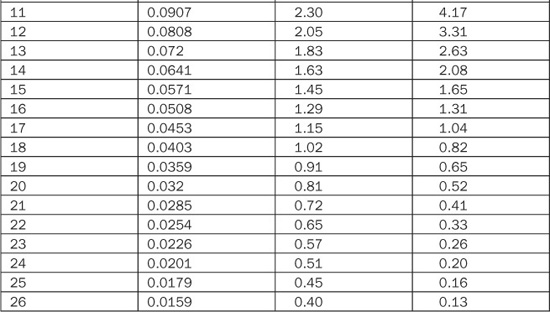
Resource

www.reuk.co.uk/AWG-to-Square-mm-Wire-Size-Converter.htm
As mentioned earlier, a wind turbine must be loaded at all times, so it always must be connected to the grid or your battery bank. To avoid damaging your charge controller, connect it to your battery bank first, then to the wind turbine. Similarly, always disconnect the wind turbine first and the battery last when you are taking things apart. (Before you disconnect the turbine, make sure it is stopped with a mechanical brake.)
Power Up! It’s also important to remember that the resistance of a wire decreases as the square of the diameter. So thick wire has less resistance than thin wire, which means less of your electricity will be lost as waste heat. However, thick wire costs more, so you are going to have to weigh your options.
Sizing wire isn’t easy, and you may do well to consult the equipment manufacturers, dealers, other wind system owners, and electricians.
Grounding
A wind turbine sits on a high tower, above everything else around it, so it is at significant risk of lightning strikes. Fortunately, it can be reasonably well protected with proper grounding, although the process often isn’t easy. The main goal of grounding is to move as much energy as possible down into the ground and away from your equipment as quickly as possible. To that end, you don’t want to use just a single ground point. Even a few ground points may not be enough if they are too close together to quickly disperse the charge.
Instead, you should install in the ground a radial network of flat copper strap around the tower, with ground rods protruding from the ribbon at twice the length of the rods. That means 10-foot ground rods would be spaced 20 feet apart. The reason you want to use copper strap instead of regular wire is because lightning is a fairly complex burst of electricity that includes high-frequency energy. Some of this energy tends to stay at the surface of the conductor, in what’s called the skin effect, and straps are better at dispersing this than tubular wire is. The strap should be at least one and a half inches diameter and at least #26 AWG (0.0159 inch) thickness.
The copper loop should be buried at least 8 inches, and preferably 18 inches, underground. If the copper runs are too long or too short they may not effectively disperse charge, so they should be between 50 and 75 feet long. There shouldn’t be any sharp bends, either, because the lightning will look for an easier path. If any run passes within four feet of a metal object, the object should be wired in. Experts suggest putting in several radials, but usually not more than four.
Note that ground rods generally disperse charge into the ground in a cylindrical pattern with a diameter that extends roughly twice their length (hence, the spacing rule). Ideally, ground rods should be covered in copper, which makes them last longer than regular or galvanized steel. Stainless steel rods will last even longer, but they are more expensive. Rods should be welded to the strap with exothermic bonds or brazing. If that’s not available, you can use high-pressure clamps and joint compound, although that will need to be periodically inspected.
It is usually easier to put in a shallower, more spread out system of grounding strap and rods, but if that isn’t an option, you may be able to “go vertical” by making it deeper, using 50-foot long rods. If your site is over solid rock or very dry soil, which doesn’t conduct well, you may need a more advanced solution and heavy-duty equipment.
Studies show there is no need to run a ground wire from the top of the tower to the earth, because there is sufficient metal in a tower to act as a conductor. Putting a copper wire in contact with the steel of the tower will cause it to rust faster, since the copper will react with the zinc in the steel. You do need to properly ground every one of the tower’s connection points with the soil, however. This means each tower “leg” and every guy wire.
Each individual guy wire needs to have a direct connection to the ground, preferably above the turnbuckles, even if you have several wires that converge into a single anchor. Make sure you don’t have any copper touching regular or galvanized steel, as that will lead to corrosion. Instead, use an intermediate, like stainless steel. Cover any joints with corrosion-resistant joint compound. Also run ground wire from all guy anchors to the center foundation block, 18 inches underground, with a ground rod every 20 feet. It’s a good idea to run an outer perimeter of ground wire around the guy points too. Use copper strap or, at a minimum, solid copper wire #4 or larger AWG.
You can also take advantage of Ufer grounds, which are named after an engineer who discovered them in World War II. Herbert Ufer proved that reinforced concrete is good at dissipating a lightning strike, since it is quite porous and has relatively high surface area.
To set up an Ufer ground, the rebar in the concrete needs to be connected together and to the rest of the ground system, ideally with solid copper wire. Don’t leave any jumps, because lightning can flash across them and crack the concrete in the process. As long as the solid copper is encased in concrete, it won’t react with the steel. Don’t use stranded copper, as that can allow moisture to seep in. It’s also better to case the concrete directly into the ground, without using forms, which act as insulators, or piling on too much backfill, which often isn’t a very good conductor.
If your house or other building is anywhere near the turbine, you will have to install a perimeter ground around that structure, preferably of copper strap, and with regularly spaced ground rods. This perimeter will then be connected to the ground perimeter of the turbine tower, as well as the standard (code-mandated) house ground and any grounds for the inverter. The reason you do this is because you don’t want all that lightning energy you just channeled into the ground from your tower to make its way into your home’s electrical system, where it could fry all your fancy electronic toys. By setting up a grounding perimeter there, you will disperse any charges.
Surge Arrestors
Even the best-laid ground wires won’t necessarily be able to stop 100 percent of a direct lightning strike. Plus, there are other potential sources of high current bursts that could affect your system. For these reasons, you still need surge arrestors (commonly called surge protectors by the general public).
No surge arrestor is perfect, and there are several different designs, each with pluses and minuses. They include the following:
• Gas discharge tubes (GDTs) In these devices, a spark gap is enclosed in a chamber filled with gas. GDTs can handle very large currents, but they are slow, so they allow a relatively large amount of current to flow through before they trip.
• Metal oxide varistors (MOVs) These devices have a metal oxide that acts as a resistor, and gets more and more conductive as current rises. They let less current through than a GDT, but they can handle less of it (Figure 10-20).

FIGURE 10-20 These metal oxide varisters (MOVs) were destroyed by a power surge, but the arrestors successfully protected the inverter of the Xiao Qing Dao Island wind project in China. Jerry Bianchi/DOE/NREL.
• Semiconductors Semiconductor-based arrestors let the lowest amount of electricity through, but they can also handle the least amount.
Devices rated specifically to deal with a direct lightning strike are sometimes called lightning arrestors, or are rated 10/350, which is a technical number describing how fast the current ramps up then down, in μs.
When it comes to a wind energy system, Solacity recommends installing a lightning arrestor before the alternator (your manufacturer may have done this; check with them for details). If the turbine’s wiring then goes underground for 50 feet or more, a less powerful second surge arrestor can be used before the rectifier, charge controller, batteries, and inverter. This arrestor could be rated at 8/20, meaning it is designed to handle a secondary strike, such as lightning hitting nearby.
According to Solacity, an arrestor should be used on the grid side of the system as well. If it is unlikely to get a direct strike, an 8/20 device may suffice. But if there is a large overhead line nearby that could attract lightning, it’s a good idea to use a full lightning arrestor (10/350).
Utility Interconnection Equipment
As part of your net-metering agreement, your utility will typically provide the equipment you need to connect to the grid. The most important piece is the electric meter. You may need a new one, because it must be bidirectional so it can track electricity coming from the grid and sent to the grid. Most utilities provide these free of charge as part of the interconnect agreement.
You may need transformers and relay switches to ensure that the proper voltage and frequency is sent to the grid. These are also usually provided by the utility.
System Meters
You will definitely need monitoring and tracking capabilities for your system, so you can see what is going on at all times, make adjustments as needed, and ensure your system is performing well (Figure 10-21). System meters will track how full your battery bank is, how much electricity your wind generator is producing, and how much electricity is in use. Operating your system without metering is like running your car without any gauges—although possible to do, it’s always better to know how much fuel is in the tank.

FIGURE 10-21 Kevin’s Skystream came with easy monitoring and tracking software. Kevin Shea.
At a minimum, you will need to have a voltmeter and an ammeter. Many wind system components also have monitoring and data logging built in, as is the case with many charge controllers and inverters. This can give you a quick idea of what is going on, although it is also a good idea to have a centralized system meter that tracks everything. Many system meters now interface with home computers or even mobile devices, allowing instant data analysis and control.
The good news is that most small wind turbines now come with system meters as part of the package. Even if they don’t, a meter isn’t very expensive ($100). But it’s definitely important.
Many smaller wind systems now come with integrated system analysis tools (Figure 10-22), which monitor performance in real time and stream the data via Wi-Fi. Skystream products have this capability, for instance.

FIGURE 10-22 It’s important to track your energy use and production. You wouldn’t drive a car without gauges, would you? Kevin Shea.
Backup Generator
We don’t spend a lot of time covering backup generators here, but suffice it to say that almost all off-grid systems have them. The generator is required for when you can’t produce enough energy with your turbine (and/or solar panels) to run all your necessary loads. Most generators burn diesel (Figure 10-23) or petroleum fuel, although it’s also possible to use natural gas, propane, kerosene, coal, or even wood.

FIGURE 10-23 Diesel generators are common backup power supplies for small wind systems, which can’t produce energy when the breezes aren’t blowing. Ken Olson/DOE/NREL.
Most generators produce AC current, so you need a separate battery charger or a charge controller and/or inverter that can accept this line and then convert it to DC to charge your batteries.
Note that the primary goal for most folks with generators is to run them as infrequently as possible. Generators tend to be noisy, smelly, and polluting. Fuel can be expensive, and you have to transport and store it.
However, system design is a balance when it comes to the generator versus size of the wind turbine. Your first impression may be to try to size the turbine large enough to never need a generator, but this is rarely practical. Such a system would likely be prohibitively expensive and overly large, and in most areas you don’t make any money on surplus energy beyond what you use (or a small percentage over that). So you’d just be giving away some of your power to the man. Even then, the biggest turbines aren’t any good if there’s no wind.
So if you are off-grid, you’ll need to have a generator. We’d suggest looking for one that is quiet and produces cleaner emissions. Even some folks with grid-connected wind systems with battery backups opt to buy a generator to have as an alternate power source if the grid is down and the batteries get depleted. It’s another expense for something you may rarely use, unless you live in an area with spotty grid service. Much of the developing world is, in fact, like that, and we are certainly aware of places where the grid goes down an average of a few times a week, often for days at a time. If that applies to you, a generator can be an important piece of a functioning system.
Summary
In this chapter, we learned that there are a number of other components required for a fully functioning wind system, beyond the turbine and the tower (Figure 10-24). These include a charge controller and batteries (if you want them), an inverter, rectifiers, disconnects, breaker panels, surge arrestors, grid-interconnection equipment (if there is a grid), wire, and system meters. Depending on your setup, many of these devices can be very important.

FIGURE 10-24 Inverters, charge controllers, and a battery bank for a system that powers a portable reverse-osmosis water filtration plant. The unit was sent to the Middle East for use in water-stressed parts of Jordan, Israel, and the Palestinian Territories. Warren Gretz/DOE/NREL.
In some cases, you won’t have much choice, because you will be getting the components packaged with the turbine. If you are building your entire system from scratch, you will have to make, improvise, or buy these parts. In most cases, these are not areas to skimp on. You don’t want to start an electrical fire because you saved a few bucks on some cheap wire.
If this chapter seems a little overwhelming or you are feeling intimidated by electrical devices, call in professional help. Hire a reputable installer with experience in the field. Even certified electricians sometimes shy away from wind energy systems if they haven’t worked on them before, because they may not be familiar with all the moving parts.
Getting everything wired up properly takes some careful attention to detail, but it also isn’t as difficult as you might think. Literally millions of wind turbines have been making electricity for more than 100 years, and the safety record is extremely good.