
Solids
|

A solid is a closed, solid body that is created in the “Part Design” workbench. A solid is generally represented by the Shape class. Depending on the geometry to create, a solid is based on a sketch, surface, operation, or transformation (Table 7.1). These respective solids are represented by child classes of the Shape class.
TABLE 7.1 Solids and Their Classes
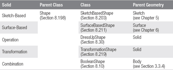
A sketch-based solid is defined by a sketch, which is drawn along a direction or rotated about an axis. These solids are assigned to SketchBasedShape class.
A surface-based solid uses surface geometry to derive its features. It describes the envelope or partial surfaces of the solid. These solids are represented with the SurfaceBasedShape class.
An operation changes the surface characteristics of an existing solid. A transformation replicates an existing solid. These solids are made from the DressUpShape and TransformationShape classes.
A special case is a solid created by a logical combination of two bodies (see Section 3.3.4). This case is called a BooleanShape.
The following sections will show how the different types of solids can be created.
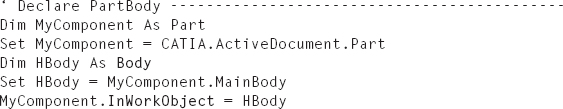
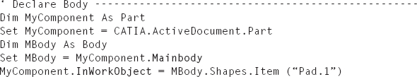
A solid is always assigned to a body (Section 3.3). To create a solid, you must first create or declare a body. The result is an object of the Body class, in which a solid can be stored. The creation and declaration of a body is presented in Section 3.3.1.
If a solid is generated, it is inserted in the tree structure after the object that is being processed. An insertion point must therefore be activated before creating a solid body. This is accomplished with the InWorkObject property of the Part class (Section 8.168). An insertion point is underlined in the construction tree.
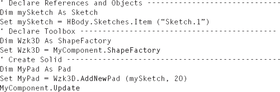
A solid is created using a 3D toolbox for solids. A 3D toolbox for solids is represented with the ShapeFactory class (Section 8.199) and is declared with the ShapeFactory property of the Part class (Section 8.168). A 3D toolbox for solids provides the “AddNew…” methods for the creation of a solid.
A newly created solid receives “In-work” status and is highlighted in the tree structure. The InWorkObject property automatically displays the new solid. Subsequent solids are added under the “In-work” of the construction tree. After solids are created, the component can be updated with the Update method of the Part class.
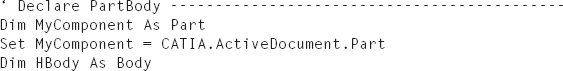
Sub PART.UpdateExample 7.1: Creating Solids
The sketch “Sketch.1” exists inside the PartBody in an open, active CATPart. A pad with a height of 20 mm is created based on this sketch (Figure 7.1).
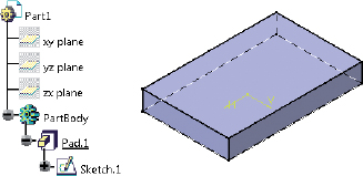
FIGURE 7.1 Result of the example “Creating Solids”


A sketch-based solid body is defined by one or more sketches. If a sketch-based solid is drawn along a straight line, it is called a prism. A sketch that is rotated about an axis is called a revolution. When a sketch is drawn along a curve, it is called a swept solid. A solid that transitions between two or more sketches is called a transitional solid. An overview of sketch-based solids is given in Table 7.2.
TABLE 7.2 Overview of Sketch-Based Solids
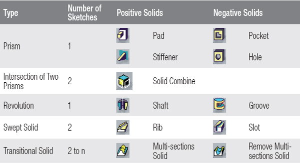
A solid may have a positive or negative definition. Solids with the same definition are added, and bodies associated with different solid definitions are subtracted (see Section 3.3). For example, if a pad and a pocket are created in a body, the intersection of the pad and pocket is omitted.
The following two sections introduce the methods for creating sketch-based solids and include two case studies.
The methods for creating a sketch-based volume body are assigned with the ShapeFactory class (Section 8.199). An overview of these methods is provided in Table 7.3.
TABLE 7.3 Methods for Creating Sketch-Based Solids
(Details of the Methods: ShapeFactory class, Section 8.199)
(Details of the Methods: ShapeFactory class, Section 8.199)
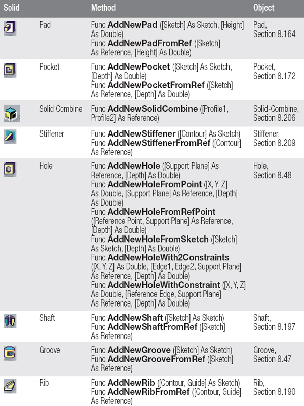
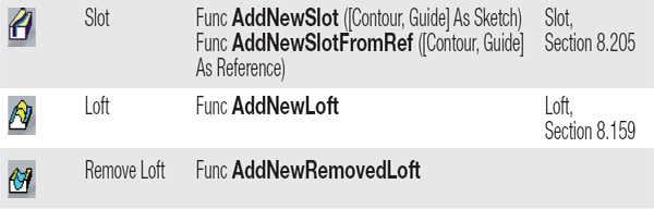
These methods require either a sketch as a parameter for an object of Sketch class (Section 8.202) or a Reference (Section 8.181). The creation of a sketch is presented in Chapter 5, and the declaration of a reference is presented in Section 3.5.
Some special objects are noted in the following section:
A hole can be defined by a sketch or a point in space. If a sketch is used, as a standard practice it should only include one point.
A revolution (Shaft or Groove) of an axis of rotation is required within a sketch (Section 5.3).
A transitional solid (Multi-sections solid) is based on a transitional area in the internal CATIA data model of the HybridShapeLoft class (Section 8.102). If an object of the Loft class is created in the first step, the object is created and declared with the AddNewLoft or AddNewRemovedLoft method using the HybridShape property of the underlying surface object.
7.2.2 Case Studies: Sketch-Based Solids
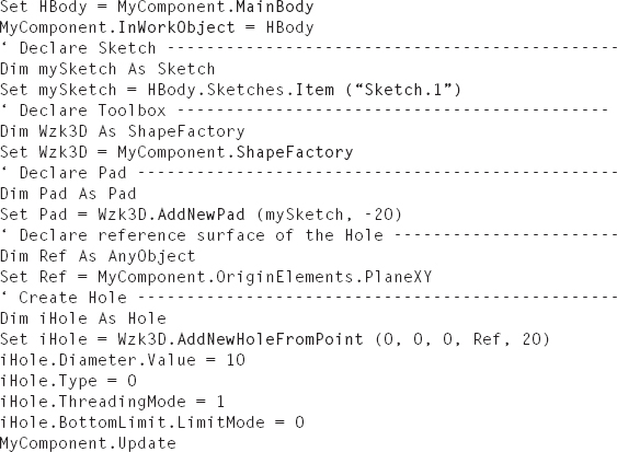
Example 7.2: Pad with a Hole
The sketch “Sketch.1” exists with a 50 × 50 mm rectangle in the PartBody in an open, active CATPart. The rectangle is on the XY plane, centrally positioned to the axis system. A pad with a height of 20 mm is created in the PartBody, and in its center a hole is created with a diameter of 10 mm (Figure 7.2).
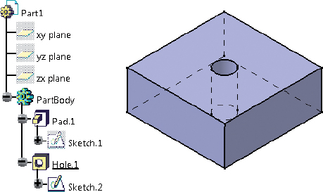
FIGURE 7.2 Result of the example “Pad with a Hole”
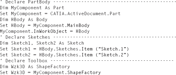
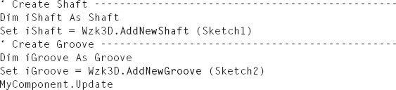
The sketches “Sketch.1” and “Sketch.2” exist in the PartBody in an open, active CATPart. “Sketch.1” describes the outer contour of the shaft, and “Sketch.2” describes the contour of the groove. For both profiles in the PartBody, a shaft is created with a groove (Figure 7.3).
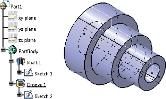
FIGURE 7.3 Result of the example “Shaft with a Groove”
A surface-based solid is a solid whose definition is based on a surface. Each surface-based solid has the SurfaceBasedShape class (Section 8.211) as its parent class. There are two possibilities for creating surface-based solids:
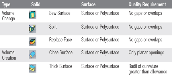
An overview of the surface-based solid, the surfaces used, and their quality requirements are provided in Table 7.4.
TABLE 7.4 Overview of Surface-Based Solids
The following two sections describe the methods for creating surface-based solids, and two case studies are presented.
7.3.1 Methods for Creating Surface-Based Solids
The methods for creating surface-based solids are assigned with the ShapeFactory class (Section 8.199). An overview of these methods is given in Table 7.5.
TABLE 7.5 Methods for Creating Surface-Based Solids
(Details of the Methods: ShapeFactory class, Section 8.199)
(Details of the Methods: ShapeFactory class, Section 8.199)
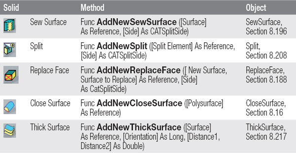
The methods require a parameter for a surface as an object of the Reference class (Section 8.181). The creation of a reference is shown in Section 3.5.
A SewSurface object is the result of surface integration. The AddNewSewSurface method integrates a surface in an existing solid by adding or removing a partial volume. Either the surface must fully share the solid, or its edge curves must lay on the surface of the solid. The same requirements apply for a surface geometry of the AddNewSplit method.
A CloseSurface object is a solid that is enclosed by a surface geometry. The surface geometry must have no gaps or overlaps. If planar openings are present in the surface geometry, they are closed automatically with the AddNewCloseSurface method. An opening is planar if its boundary curves lie on a plane. The edge curves of the surface geometry must be present, so an opening can be closed.
A ThickSurface object is the result of a surface thickening. The AddNewThickSurface method may be required to thicken a surface or a polysurface whose radius of curvature is greater than the thickness of the surface geometry.
7.3.2 Case Studies: Surface-Based Solids
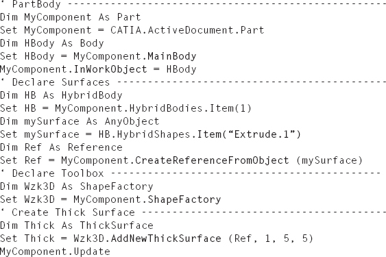
Example 7.4: Thick Surface
The geometrical set “Surface” exists with the extrusion “Extrude.1” in an active, open CATPart. The extrusion surface is thickened equally by 5 mm in both directions, and the result is stored in the PartBody (Figure 7.4).
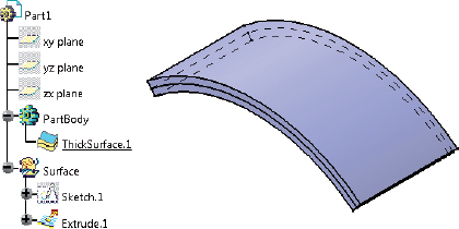
FIGURE 7.4 Result of the example “Thick Surface”
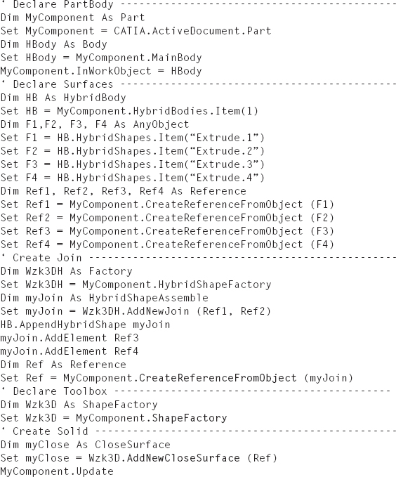
The geometrical set “Surfaces” exists with four extrusion surfaces, “Extrude.1” through “Extrude.4,” in an active, open CATPart. The extrusion surfaces are combined to form a joined surface from which a closed surface is created. The solid will be built in the Part-Body (Figure 7.5).
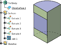
FIGURE 7.5 Result of the example “Close Surface”
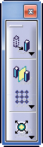
A transform-based solid is a solid resulting from a transformation. A transformation is caused by changing or replicating a solid. A change moves, rotates, or scales a solid. A replication produces multiple identical features of a solid.
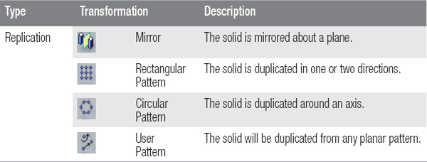
An overview of the change transformations is given in Table 7.6 and that of replication transformations in Table 7.7.
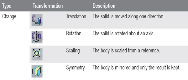
TABLE 7.7 Overview of Replication Transformations
The following two sections describe the methods for creating transformation-based solids, and two case studies are presented.
7.4.1 Methods for Creating Transformation-Based Solids
The methods for creating transformation-based solids are assigned with the ShapeFactory class (Section 8.199). An overview of the methods for creating change transformations is given in Table 7.8 and that for creating replication transformations in Table 7.9.
TABLE 7.8 Methods for Creating Change Transformations
(Details of the Methods: ShapeFactory class, Section 8.199)
(Details of the Methods: ShapeFactory class, Section 8.199)
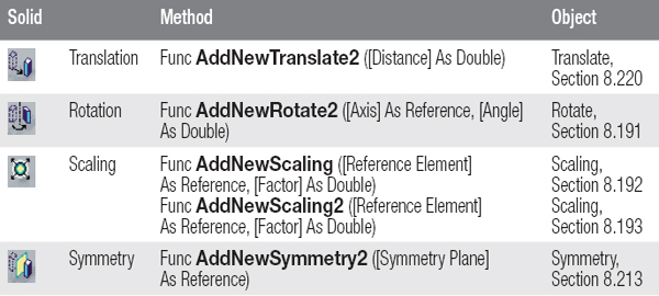
TABLE 7.9 Methods for Creating Replication Transformations
(Details of the Methods: ShapeFactory class, Section 8.199)
(Details of the Methods: ShapeFactory class, Section 8.199)
Some methods require parameters as objects of the Reference class (Section 8.181). Creating a reference is shown in Section 3.5.
The AddNewTranslate2, AddNewRotate2, AddNewScaling, AddNewScaling2, AddNewSymmetry2, and AddNewMirror methods do not have a body as a parameter and apply the transformation to the solid that is being processed (see Section 7.1).
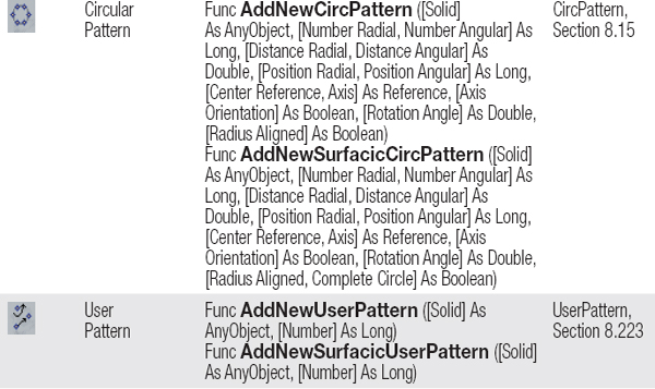
Each pattern represents only the solid, which is specified as a parameter in its method. A user pattern is determined by the execution of the AddNewUserPattern method. The positions in the pattern must be determined later with the AddFeatureToLocate-Positions method of the UserPattern class. This method generally uses a sketch that contains points.
7.4.2 Case Studies: Transformation-Based Solids
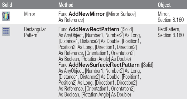
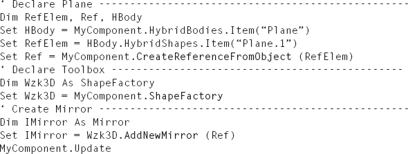
Example 7.6: Mirror
In an open, active CATPart, the PartBody contains the pad “Pad.1” and the geometrical set “Plane” with a plane “Plane.1.” The pad should is mirrored around the plane. The result will appear under the object “Pad.1” in the tree (Figure 7.6).
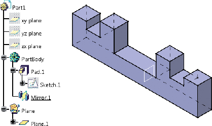
FIGURE 7.6 Result of the example “Mirror”
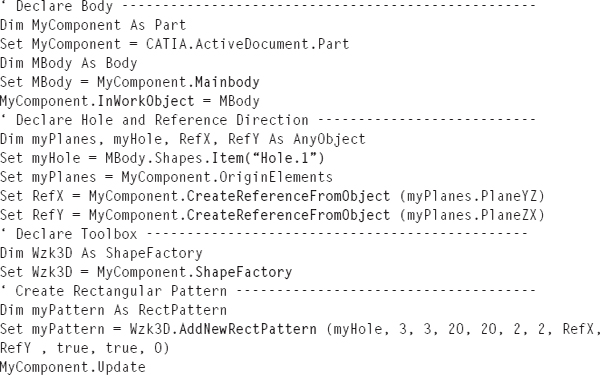
In an open, active CATPart, the PartBody contains the pad “Pad.1” and the hole “Hole.1.” The hole is to be replicated along the positive and negative X and Y directions with a distance of 20 mm. The result is a pattern with 3 × 3 holes, with the original hole located in the center of the pattern (Figure 7.7).
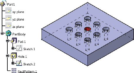
FIGURE 7.7 Result of the example “Rectangular Pattern”

An operation is a change of any edges or faces of a solid. An operation can change the topology of a body or just its BRep names (see Section 3.5.4). When an operation changes the number of edges or sub-surfaces of a solid or its form, this is referred to as a topological change. The creation of a fillet, chamfer, or shell element are examples of topological changes, since a solid receives additional surfaces. The creation of a thread operation does not change the topology of a solid, but the BRep names of the involved surfaces are modified. An overview of the surface operations on a solid is given in Table 7.10 and that of edge operations on solids in Table 7.11.
TABLE 7.10 Surface Operations on Solids
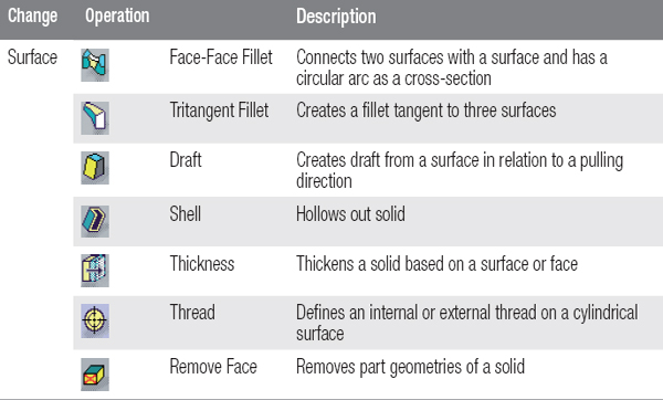
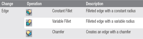
TABLE 7.11 Edge Operations on Solids
The following two sections describe the methods for creating operations on solids, and two case studies are presented.
The methods for creating operations on solids are assigned with the ShapeFactory class (Section 8.199). An overview of the methods is given in Table 7.12.
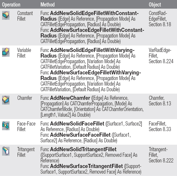
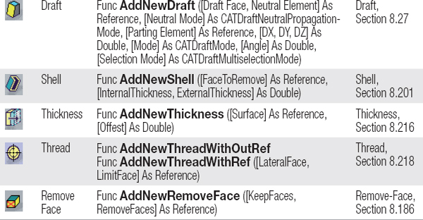
TABLE 7.12 Methods for Creating Operations on Solids
(Details of the Methods: ShapeFactory class, Section 8.199)
(Details of the Methods: ShapeFactory class, Section 8.199)
When declaring a reference that is used as a parameter in one of the methods listed, note that:
To reflect this in a macro, the method should create the operation with an empty reference as a parameter to pass. Then set the methods of the created object, even the edges or faces (see Example 7.8). The declaration of an empty reference is explained in Section 3.5.3.
7.5.2 Case Studies: Operations
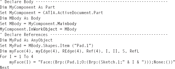
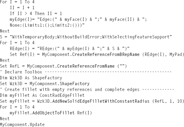
Example 7.8: Constant Fillets
The pad “Pad.1” exists in the PartBody in an open, active CATPart. The pad is based on the sketch “Sketch.1.” The pad is filleted on all four vertical edges with radius of 10 mm (Figure 7.8).
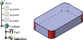
FIGURE 7.8 Result of the example “Constant Fillets”
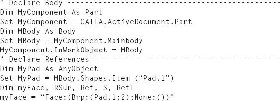
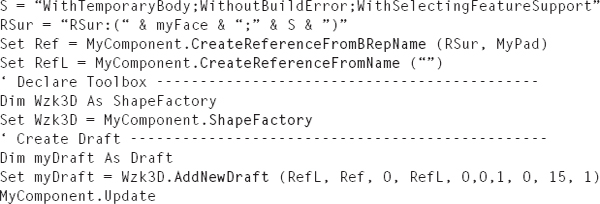
In an open, active CATPart, the pad “Pad.1” exists in the PartBody with a circular contour. The pad’s outer surface is drafted at 15°. The draft direction is (0, 0, 1). The edge at the top of the pad must not be dimensionally changed. The result is shown in Figure 7.9.
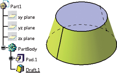
FIGURE 7.9 Result of the example “Draft”
..................Content has been hidden....................
You can't read the all page of ebook, please click here login for view all page.