Biological and medical applications
Modern polymers have wide ranging applications in biology and medicine. A key determinant of biocompatibility for implantable biomedical devices is the interaction of its surfaces with proteins in the organism. The ion implanted polymer surface forms strong covalent bonds with proteins, resulting in total coverage of the surface, whilst preserving the biological properties (conformation and activity) of the proteins. The ion implantation of polymer surfaces opens up the possibility of functionalizing the surface for cell attachment with a coating of extracellular matrix or adhesion proteins. The modified polymer surface then becomes completely covered with living cells. In the case of the ion-modified polymer, proteins from the organism are covalently attached on the polymer surface in their native conformations and the organism’s immune system cannot recognize the polymer as a foreign body. The polymer becomes integrated into the organism’s tissues.
Keywords
polymer implant; biocompatibility; protein attachment; cell growth; foreign body reaction
Modern polymers have a vast application in biology and medicine. Most medical devices are made from polymer materials, for example supporting devices for patients, storing and treatment devices for medications, physiological substances and organs, and prosthetics for different applications, including artificial organs, skin, and extremities. Replacements for human and animal body parts made from polymer materials must have high biocompatibility. The polymer must induce a low inflammatory reaction from the organism and have: low toxicity, similar elastic properties to the relevant biological tissues, and an application appropriate lifetime in the organism with satisfactory mechanical strength. In some applications, optimal biocompatibility also requires integration with appropriate local tissues, and in this case it demands a biologically active surface that drives integration with a particular cell type. There has been rapid growth in the use of polymer devices in medical applications over the last few years. However, despite this success, there are still several major problems that must be solved to allow ideal performance in the human body. The modification of a polymer surface using ion implantation can be advantageous in many biological and medical applications. Here, we consider a few applications of ion implantation for medical polymers, which were revealed during our scientific projects and contacts with medical companies.
A key determinant of biocompatibility for implantable biomedical devices is its interaction with proteins in the organism. The attachment of proteins to most polymer surfaces occurs seconds after inserting a polymer prosthetic into a living organism. The surface properties of the implanted material determine the conformation and orientation of the proteins that adsorb, as well as the composition of the adsorbed layer by virtue of varying affinity with different proteins. The protein coating—in particular the presence of denatured proteins in it—is typically what stimulates a response by the organism’s immune system. Hence, control of protein interactions is an important aspect of biocompatibility for implantable prosthetic devices [1].
There are also applications of surface-attached enzymes in the food, chemical, biotechnology, and medical diagnostic industries. An example is a biosensor (biochip) based on enzyme activity for detection of antibodies in media for testing blood serum [2]. A biochip has to contain attached protein dots distributed on the polymer substrate. Proteins have to be active on the polymer, fixed at their position, and read after soaking in analyte solution. Therefore, the polymer surface must be attractive for proteins, enabling strong protein adhesion, and at the same time it must preserve the biological properties (conformation, activity) of the proteins. It must also simultaneously prevent the adhesion of extra unwanted proteins, as these contribute to background noise in biological assays.
We used different proteins for attachment to various polymers [3–20]. Good models for investigation of protein attachment are provided by enzymes such as horseradish peroxidase (HRP) and bovine liver catalase. HRP and catalase are proteins whose enzyme activity can be exploited in colorimetric assays that test for their bioactivity when immobilized on a surface. The molecular weights of catalase and HRP are 57 and 44 kDa, respectively. Catalase and HRP protect cells from the toxic effects of hydrogen peroxide and catalyze the hydrolysis of hydrogen peroxide into oxygen and water according to the reaction:
2H2O2↔O2+2H2O (9.1)
Catalytic activity is provided by the presence of a porphyrin ring in the protein molecule. The catalytic activity depends strongly on the conformation of the protein molecule. This activity can be lost at elevated temperature or extreme pH, or due to disturbance by a chemical agent. The polymer surface can also influence protein conformation and, hence, denature the protein due to intermolecular interactions between the protein molecule and the polymer surface.
A protein molecule has hydrophobic and hydrophilic parts and can, therefore, physically adsorb onto untreated hydrophobic polymer surfaces. In its natural and bioactive state, the protein molecule is enclosed in a water shell, with the hydrophilic parts dominating on the outside of the protein and the hydrophobic parts mostly hidden inside. Most polymer macromolecules are hydrophobic and, therefore, attractive to the protein’s hydrophobic groups via Van der Waals forces. On contact with a hydrophobic polymer surface, the conformation of the protein (which typically resides in a state suitable for a water environment) changes and the hydrophobic parts interact with the polymer macromolecules. In this case, protein is unfolding and conformational changes that are likely to adversely affect the bioactivity occur.
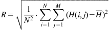
We placed the HRP molecule in solution on a smooth polystyrene (PS) film that had been spincoated onto silicon wafer. The dimensions of the HRP molecule are 3.5 nm×6.0 nm×7.5 nm [21,22]. Figure 9.1 shows atomic force microscopy (AFM) images for an untreated PS surface with the attached HRP layer. One can see hills distributed on the polystyrene surface. The surface morphology was analyzed based on quantitative analysis of AFM experimental data. The roughness of the surface is characterized by root mean square (RMS) as a parameter of deviation of surface pixels from the medium surface level:
(Eq. 9.1)
 (Eq. 9.1)
where H is the surface pixel level, I and j are pixel locations, and ![]() is the mean surface level.
is the mean surface level.
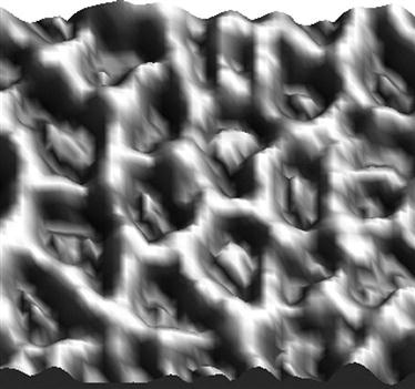
The RMS roughness parameter for the untreated spincoated PS film is 0.78 nm, which corresponds to the RMS parameter of the initial silicon wafer. The RMS roughness of the surface after HRP attachment is 4.3 nm. The RMS parameter characterizes the average deviation of the surface pixels without detailed analysis of lateral spacing of various features. The detailed analysis of the histogram of roughness events for HRP adsorbed on the polystyrene surface gives an 8 nm hill height. From this and the AFM image, it can be determined that the height of the protein hills is approximately 8–10 nm, similar to the height of a single HRP molecule (7.5 nm) [21].
Another useful roughness parameter is the power spectral density (PSD), which calculates roughness amplitude squared as a function of spatial wavelength of the features:
(Eq. 9.2)
where L is the size of the AFM image, and H(kx,ky) is the result of the Fast Hartley transformation:
(Eq. 9.3)
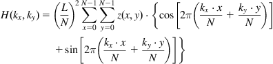 (Eq. 9.3)
In these terms, PSD is a Fourier decomposition of the image into spatial frequencies, and features of the PSD curve are interpreted as the periodicity of the surface features with definite dimensions. The PSD parameter for lateral analysis of the HRP islands on untreated polystyrene gives a peak at 92 nm, which characterizes the average distance between the islands. Given that the protein islands have a height of about 10 nm, we calculated the percentage coverage of hills with a height of 10 nm and more to determine the coverage of protein while minimizing the influence of surface roughness. The percentage coverage of hills is approximately 27% of the whole surface. Using these contours, the first neighbor distance (FND) or average minimum distance between hills was calculated. For HRP hills of 10 nm, we obtained a value of 64 nm for FND. A combination of AFM, ellipsometry, and FTIR results indicates that the HRP protein molecules form islands with heights of around 8 nm (corresponding to the longest dimension of the protein molecule) and lateral sizes of around 30 nm on the untreated polymer surface (Figure 9.2), with a distance between islands of 64 nm [4].
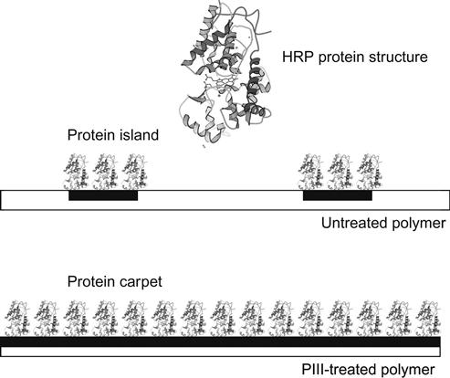
In contrast with the untreated surface, the PIII-modified surface of polystyrene is completely covered with HRP molecules, as in a carpet. The AFM, FTIR, and ellipsometrical analyses show that 100% of the surface is covered with a uniform monolayer of HRP [4]. The thickness of the covering equals the longest dimension of the protein molecule. Such vertical positioning of the HRP molecule reduces the contact area with the polystyrene substrate, allowing maximal contact with the water media and covers maximally the polystyrene surface with protein molecules.
On a modified polymer surface the protein molecule has a number of intermolecular interaction possibilities. For example, aromatic condensed structures as acceptors of protons attract polar groups of molecules with flexible protons such as carboxyl groups, hydroxyl groups, and amine groups. The HRP molecule contains many such groups sufficient for donor/acceptor interactions. There are a wide number of active groups on the modified polymer surface: carboxyl, aldehyde, hydroxyl, peroxide as well as free radical groups, which could react with active groups on the protein to form covalent bonds between polymer surface molecular groups and protein molecules. Hydrogen acceptor and donor groups are presented in the modified polymer surface and they could be included also in hydrogen bonds between surface molecules and protein molecules.
To determine the mechanism that immobilizes the protein on the modified polymer surface, we tried to remove the attached HRP and catalase protein molecules by chemical detergents, including sodium dodecyl sulfate (SDS), Triton X100, Tween 20, and NaOH solutions. These detergents have a combination of polar and nonpolar groups, proton donor and acceptor groups, as well as strong ionic groups, that they can take part in all kinds of intermolecular interactions. When exposed to active detergents, the protein molecules lose their native conformations due to penetration of the detergent molecules between the protein chains. In addition, the detergent molecules penetrate between the protein and the polymer surface and separate the protein chains from the polymer macromolecules. The intermolecular contact of the protein molecule with the polymer surface becomes disrupted. The protein molecule does not stay on the polymer, and in the absence of any covalent bonds with the polymer macromolecules it can be washed off.
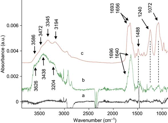
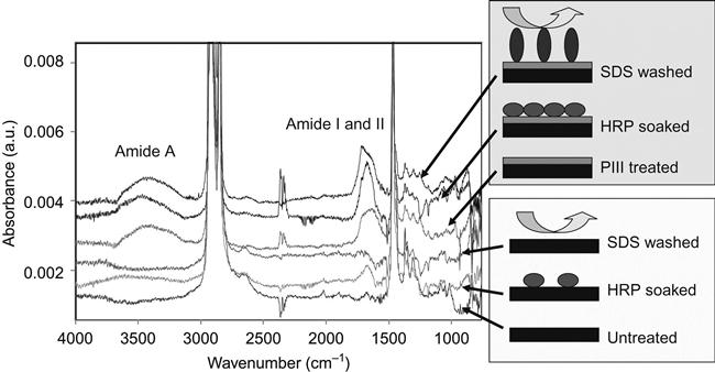
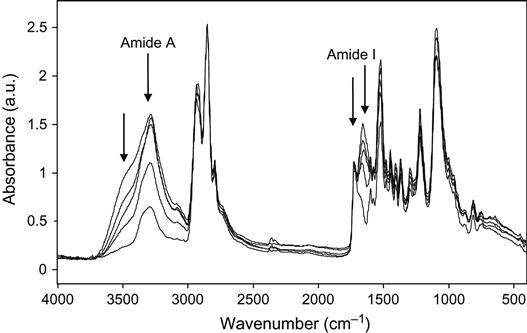
In our experiments, the proteins were completely removed from the untreated polymer surfaces. We have tested a number of different proteins attached to a number of different polymers. The SDS, Tween 20, Triton X100, and NaOH solutions easily removed the attached protein from untreated polymer surfaces. For thick and strongly adsorbed aggregated protein layers, it was sometimes necessary to heat the detergent solution to prevent steric hindrance of the interface by the protein layer. Figure 9.3 shows FTIR ATR spectra of protein attached to an untreated polyethylene surface. The presence of protein is observed by the appearance of the specific spectral lines of the protein backbone: Amide A, Amide I, and Amide II lines. FTIR spectra do not show protein lines after the untreated polyethylene surface with attached protein layer is washed in detergent solution.
However, when the surface is modified by ion implantation, the protein cannot be removed by any detergent at any concentration at any temperature, even in boiling detergent solution (100°C). There is no way to explain the effect of protein attachment after detergent without covalent bonding between the protein and polymer. Therefore, the protein molecules are bonded covalently with the polymer surface and only destruction of the polyethylene surface layer or protein backbone can remove the protein molecules from the surface.
Thus, a plausible mechanism to explain the protein attachment on the modified polymer is by chemical reaction of an active group on the modified polymer surface with the protein molecule. The protein molecule in solution can take part in a number of chemical reactions, for example, amine, amide, aldehyde, carboxyl acid, unsaturated carbon–carbon groups, and others. However, experiments exploring protein attachment on different polymer surfaces that contain the active groups (noted above) showed that the protein is not covalently attached on such polymers. Only when the surface contains active radicals—such as created in ion implantation processes—is the protein attachment covalent. Further evidence for the radical reaction mechanism is that only when the modified surface is deactivated with radical traps, the attachment of the protein is not covalent. Therefore, the radicals generated by ion implantation treatment in the polymer surface layer are responsible for the covalent protein attachment. Further confirmation is provided by experiments with aminoacids and polyaminoacids that showed that all aminoacid fragments in the protein molecule can take part in the covalent bonding on the modified polymer surface. This is attributed to the very high reactivity of the radicals and it provides universality of the protein attachment, implying that all proteins can be immobilized in this way.
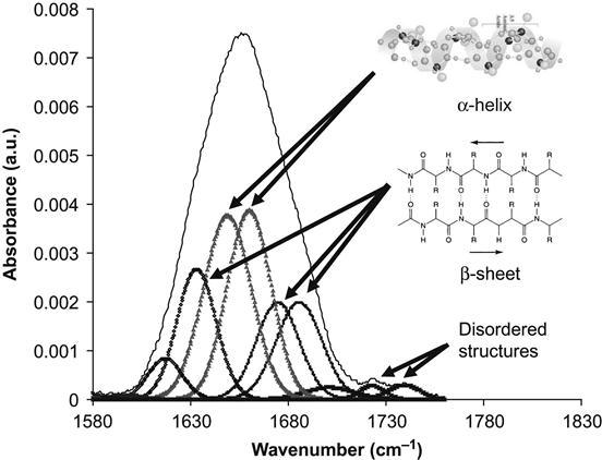
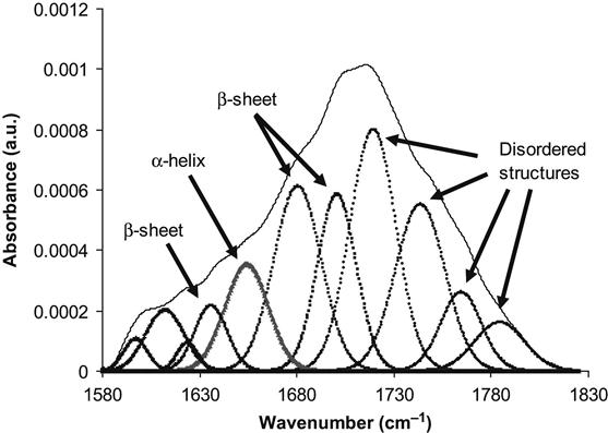
The conformation of the protein can be analyzed by the examining the Amide I absorption line of its FTIR spectra. We analyzed the conformation of HRP molecules attached to the polyethylene surface. The Amide I line is formed by separated individual lines related to vibrations of the amide group in the backbone of the protein molecule. Each line corresponds to combinations of the C![]() O stretch vibration (main contribution, about 40–60% of energy), the N
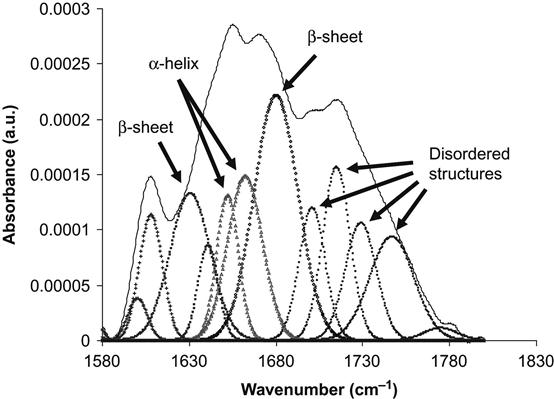
O stretch vibration (main contribution, about 40–60% of energy), the N![]() H deformation vibration (20–30% of energy) and some complex vibrations of bonds and angles in the amide group [23]. Such group vibrations are sensitive to the formation of hydrogen bonds and to the conformation of the protein molecule. Usually, the position of the lines is different for amide vibrations in α-helixes, β-sheets, and disordered chains of the protein molecule. The fitting procedure applied to the Amide I line based on literature and our own data shows the presence of all these structures in the attached HRP molecule on the untreated polyethylene surface (Figure 9.4). The conformation of the HRP molecule on the ion-modified polyethylene surface is different: the lines of disordered structures become more intense in comparison with the HRP spectra from the untreated polyethylene (Figure 9.5). However, the same region of spectra is related to vibrations of the carbonyl groups in the ion-modified surface layer of the polyethylene. These carbonyl groups appear as a result of polyethylene surface layer oxidation, and because they evolve with time, complete subtraction of the oxidized layer spectra cannot be achieved. The spectra of the SDS-treated surface show a sharp increase in the intensity of the disordered structure lines and a decrease in the intensity of α-helix and β-sheet lines of the HRP molecules (Figure 9.6). The strong increase in the intensity of disordered structure lines for SDS-washed HRP molecules supports the fact that protein molecules are strongly unfolded and lose their native conformation when immersed in the SDS detergent. Despite this major loss of native conformation, the protein molecules are still attached to the polyethylene surface. Disordered structures are observed in the attached HRP molecules on the ion-modified polyethylene surface before using detergents, indicating that some molecules also lose their native conformation on attachment to the ion-modified polymer surface.
H deformation vibration (20–30% of energy) and some complex vibrations of bonds and angles in the amide group [23]. Such group vibrations are sensitive to the formation of hydrogen bonds and to the conformation of the protein molecule. Usually, the position of the lines is different for amide vibrations in α-helixes, β-sheets, and disordered chains of the protein molecule. The fitting procedure applied to the Amide I line based on literature and our own data shows the presence of all these structures in the attached HRP molecule on the untreated polyethylene surface (Figure 9.4). The conformation of the HRP molecule on the ion-modified polyethylene surface is different: the lines of disordered structures become more intense in comparison with the HRP spectra from the untreated polyethylene (Figure 9.5). However, the same region of spectra is related to vibrations of the carbonyl groups in the ion-modified surface layer of the polyethylene. These carbonyl groups appear as a result of polyethylene surface layer oxidation, and because they evolve with time, complete subtraction of the oxidized layer spectra cannot be achieved. The spectra of the SDS-treated surface show a sharp increase in the intensity of the disordered structure lines and a decrease in the intensity of α-helix and β-sheet lines of the HRP molecules (Figure 9.6). The strong increase in the intensity of disordered structure lines for SDS-washed HRP molecules supports the fact that protein molecules are strongly unfolded and lose their native conformation when immersed in the SDS detergent. Despite this major loss of native conformation, the protein molecules are still attached to the polyethylene surface. Disordered structures are observed in the attached HRP molecules on the ion-modified polyethylene surface before using detergents, indicating that some molecules also lose their native conformation on attachment to the ion-modified polymer surface.
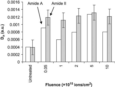
If a protein molecule is bonded covalently, there is a danger that the protein molecule is less active, because the conformation of the protein molecule can be changed and because it is pinned to the surface. The test for protein activity was done based on the well-known hydrogen peroxide reaction viewed by a colorimetric TMB assay—75 µl of 6 mM hydrogen peroxide was added to the polymer surface and incubated for 6 min by shaking; after incubation, 3 µl were removed and the remaining peroxide was assayed by a modified method of Cohen [24]. The hydrogen peroxide was added to 0.25 ml of a solution consisting of a mixture of 0.6 N H2SO4 and 10 mM FeSO4, and 20 µl of 2.5 M KSCN was added to develop the color. Absorbance was measured at 475 nm using a DU 530 Beckman spectrophotometer. The absorbance is proportional to the number of active HRP molecules in the solution. Because prior to the assay the polymer was washed six times in buffer without protein, and the buffer solution from the last wash does not show any protein activity, the activity can be attributed only to protein molecules attached to the polymer surface. The activity of the protein increases on ion-implanted surfaces compared to untreated surfaces from absorbance of 0.2 to 0.7 for polyethylene and from 0.07 to 0.56 for polytetrafluorethylene. The amount of active immobilized protein does not depend on the fluence (Figure 9.7). The same result is observed for the intensity of amide protein backbone lines in the FTIR ATR spectra of the polymer surfaces. For example, the Amide II and Amide A line intensities increase sharply after ion implantation of the polytetrafluorethylene surface and further increases in fluence do not affect the amount of immobilized protein (Figure 9.8). Interestingly, the ability of the polymer surface to immobilize protein covalently remains for months after the ion implantation treatment, if the modified polymer is stored under normal laboratory conditions. Thus, the ion-modified polymer surfaces can easily attach enzymes and the enzymes remain functional.

The universal character of protein attachment after ion implantation treatment is supported by similar experiments with HRP, soya bean peroxidase, catalase, tropoelastin, fibrinogen, fibronectin, and many other proteins. If the ion beam is focused or the ion beam treatment is done with a mask, the protein may be covalently attached in a pattern. For example, dot patterns as used in biochip technology have been generated: protein molecules can be easily removed from the untreated areas using a detergent, and the remaining molecules are attached to the implanted patterns. In this way, a polymer substrate with patterns of attached proteins can be prepared for biochips.
The ability of the modified polymer surface to attach proteins can be used also for the improvement of cellular responses to an implanted biomedical device. Cell attachment to the extracellular matrix occurs via specialized proteins in the cell membrane or transmembrane receptors, such as integrins. Cell membrane proteins have strong specific interactions with active sites on the various proteins that make up the fibers of the extracellular matrix in living organisms. These extracellular matrix proteins (or adhesion proteins) include collagen, fibronectin, vitronectin, laminin, and tropoelastin. The fact that the ion-implanted polymer surface is able to covalently immobilize protein opens up the possibility that the surface could be functionalized for cell attachment with a coating of extracellular matrix or adhesion proteins. The adhesion of cells to artificial polymer substrates is of great significance for: growing cell cultures in artificial media; cell manipulation in bionic devices; growing artificial tissues and organs; and for human and animal implants. The attached cell must be living, have good adhesion, and produce new cells (mitosis).
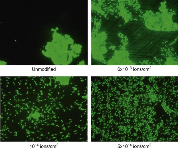
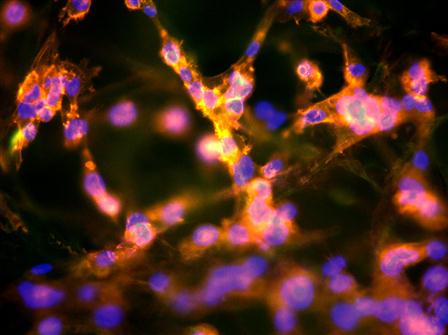
A human endothelial cell line HMEC-1 was attached to polyethylene and polytetrafluorethylene after ion treatment. The cells were seeded on the samples with a concentration of 5×10⁴ cells/cm2 in 200 µl medium (MEM-Earle supplemented with 10% fetal bovine serum (FBS), 1× MEM vitamins, 2 mM N-acetyl L-alanyl L-glutamine, 1× amino acids). They were allowed to adhere for 2 h and then the medium was filled up to 1 mL per sample. The samples with cells were stored in an incubator at 36.7°C for 2 days. After 4, 6, and 8 h, in the first experiments, an Alamar Blue™ test was performed. In a second set of experiments, the cells on the samples were fixed in 0.2% paraformaldehyde in PBS and stained for fifteen min with rhodamine at 37°C (green). In a third set of experiments, the cells on the samples were fixed in 0.2% paraformaldehyde in PBS and stained with phalloidin-TRITC and DAPI for polymerized actin of the cytoskeleton (red) and cell nuclei (blue). Images were taken by fluorescent microscopy and cell distributions calculated.
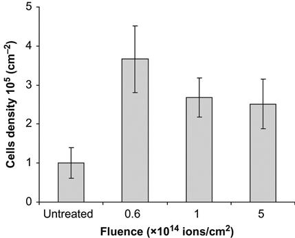
The images of cells on the polytetrafluorethylene surface after 2 days are presented in Figure 9.9. On the untreated surface, the cells form islands with a high density of cells. The image looks similar to the initial distribution of cells at seeding. On an ion-treated surface, the cells are uniformly distributed over the whole area of the sample. The number of cells is three times greater on the treated surface than on the untreated surface (Figure 9.10). This indicates that the cells grow well on the ion-treated surface.
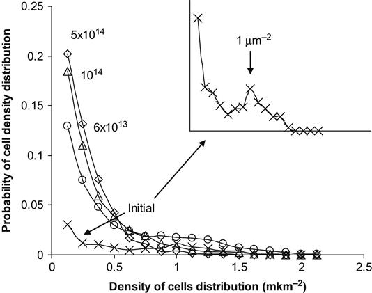
A quantitative analysis of cell density distribution can be obtained by calculating the number of cells, nij, attaching in each unit area, Sij. The number of areas with nij cells can be interpreted as the probability to find a particular density of cells in a given area. The results of such an analysis are shown in Figure 9.11 for cells distributed on a polytetrafluorethylene surface. The distribution of cells was calculated for 8 µm2 unit areas, which is close to the area of a single cell spread on a cell friendly substrate. The most probable cell density for an untreated polytetrafluorethylene surface corresponds to cell islands with a single cell area of 1 µm2. With ion implantation treatment of the surface, the peak of probability corresponding to islands disappears and the cell distribution density probability becomes maximal at one cell per 8 µm2 unit area (i.e., 0.125 cells/µm2). This means that the cells are spread up to 8 µm2 square for one cell.
A uniform spreading of the cells on a treated surface can be observed on materials made of fiber. For example, we observed cells on an expanded polytetrafluorethylene (ePTFE) surface. This material has the same chemical structure and properties as the polytetrafluorethylene film, but it has a felt structure containing thin (µm) fibers. The cells on untreated ePTFE fibers sit compactly to minimize the contact area with the fiber surface (Figure 9.12). The cells on the ion-treated ePTFE fibers cover the whole surface of the fibers (Figure 9.13).

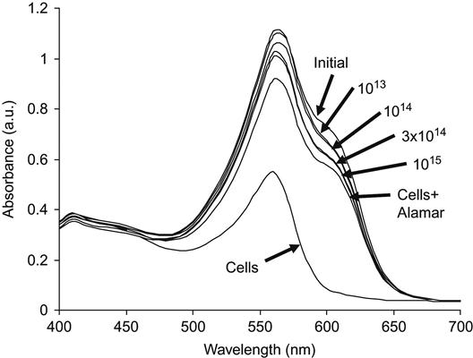
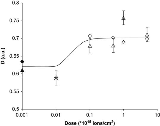
The Alamar Blue assay was used to test for living cells on a polytetrafluorethylene surface. When Alamar Blue is added to solution with seeded cells, the dye penetrates into living cells but does not penetrate into dead cells. UV-vis spectra then show the concentration of Alamar Blue that remains in the solution (Figure 9.14). For example, the results of a living cell analysis are presented for polyethylene after PIII treatment. For untreated (initial) polyethylene, the number of living cells was minimal, as indicated by the maximal intensity of the 630 nm Alamar Blue line in the solution. The assay absorbance intensity decreases significantly for PIII-treated polyethylene surfaces and continues to do so for increasing treatment fluence. This shows that the number of living cells increases with increasing PIII-treatment fluence. The absorbed value of the Alamar Blue assay, calculated as the difference between the buffer absorbance at 570 nm and the Alamar Blue absorbance at 630 nm, shows the activity of the cells adhered to the polyethylene surface. This data as a function of PIII-treatment fluence is shown in Figure 9.15. Cell activity increases for the ion-modified polyethylene surfaces, but after a fluence of 1014 ions/cm2, the cell activity does not change with further increases in fluence. At this fluence, sufficient modification of the polymer surface occurs such that complete coverage of the surface with living cells is achieved—essentially, the polymer becomes a friendly substrate for cell life and growth.
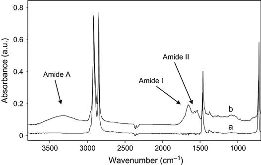
Because the attachment of the cells occurs through the attachment of proteins, the proteins remain attached to the polymer surface after removing the cells, and indeed this was observed in the previous experiments. FTIR ATR spectroscopy detected proteins attached to the polymer surface after culturing and then removal of the cells. These spectra for unmodified and PIII-treated polyethylene are shown in Figure 9.16. The spectrum of untreated polyethylene contains weak protein absorption lines, whereas the spectra of the PIII-modified samples contain strong Amide A, Amide I, and Amide II protein absorbance lines. These lines remain in the spectra after washing in water and detergents indicating that the proteins were attached covalently during the cell culture as in previous experiments with protein solution.
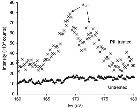
XPS spectra of polyethylene also show the protein attachment to the ion-treated polytetrafluorethylene surfaces: spectra in the S2p doublet region are shown in Figure 9.17. The spectrum of untreated polytetrafluorethylene does not contain the sulfur line after cell attachment. This means that proteins are not detected on the untreated surface. The spectrum of the PIII-treated surface shows peaks, which indicate the presence of the sulfur atoms of the protein molecules and confirms that protein is attached to the modified polymer surface.
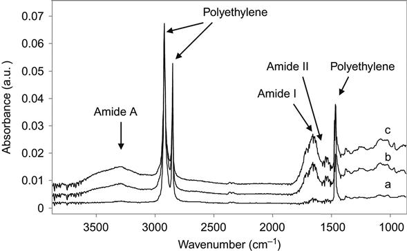
The protein spectral lines also appear in the spectra of ion-treated polyethylene after implantation into a living organism (Figure 9.18). Polyethylene samples were surgically inserted into a rat. The samples were placed under the skin on the back. After times of up to 9 months, the samples were surgically removed and washed. The FTIR ATR spectra were then recorded. The spectrum of the untreated sample did not contain any absorption lines additional to those of the polyethylene macromolecules. The spectrum of the 20 keV nitrogen ion-treated sample contained Amide A, Amide I, and Amide II lines, attributed to the vibrations of proteins. These protein lines remained after rigorous washing with water, detergents, and solvents such as ethanol and toluene. Therefore, the proteins from the organism were covalently attached to the ion-modified polyethylene surface, as observed in cell culture and protein experiments.
Covalent bonding to the polymer surface, and retention of active protein conformation, is very important. The modified surface after ion implantation treatment becomes attractive to all proteins. In living organisms, the modified polymer is covered by the organism’s own proteins immediately after the first contact with the media of the organism. A complete coverage of protein occurs and the polymer surface does not then contact directly with the organism media, including phagocytes, leukocytes, macrophages, and other components of the immune system. All cells of the organism make contact with proteins adsorbed on the polymer surface instead. This means that if the immobilized proteins maintain their native conformation, the organism’s immune system cannot recognize the artificial polymer implant covered by its own proteins and does not isolate it from the organism by invoking a foreign body immune response. The polymer implant becomes like its “own” organ because it is covered by its “own” proteins.
Ion beam implantation was also applied to industrial polymer implants that can be used in humans. The use of polymer implants as human organ replacements has become far more significant over the last few decades primarily due to: the development of new materials which have similar properties to human tissue; and the development of new methods in surgery such that a larger number of human organs can be replaced. One important field in artificial organ implantation is mammary prosthetics.
In modern cosmetic surgery, three polymer materials are usually used for mammary prosthetics: silicone rubber, polyacrilamide gel, and polyurethane foam. Polyurethane is used least, but it is being considered as a future material for implants. The problem with silicone rubber for human organisms is due to the difference between silicone and human tissue. Biological tissue naturally degenerates. Death of an organism’s cells and destruction of the cell’s molecular components are fundamental processes in a cell’s lifecycle. The products of such degradations are recycled and used as building blocks for new proteins, sugars, lipids, and other molecules. The process of regeneration of human and animal organisms by themselves is part of life. However, silicon is a foreign substance that cannot be utilized by an organism’s regeneration system. The degradation products of silicone cannot be released from an organism in the normal way through the urinary organs; these products can only be accumulated elsewhere in the organism. Apart from the inertness of the silicone degradation products, their circulation and accumulation can have a negative influence on the functionality of the organism as a whole. Therefore, prolonged contact of the organism’s media with silicone prosthetics is not ideal.
Another situation arises with polyacrylamide gel and polyurethanes. These polymers degrade with the formation of amines, amides, and glycols, which can be utilized in biochemical reactions in the organisms or released from the organisms in the usual ways. The products of degradation are not collected in the organism. However, such products can cause toxic reactions if the concentration of the products is higher than their toxic level. Therefore, the problem of biocompatibility for such polymers is connected with their rate of biodegradation.
Implantable-grade polyurethane is used as a material for artificial diaphragm membranes, artificial joints, meniscal prosthetics, breast prosthetic shells, artificial hearts, bone, and other implantable devices. Polyurethane based on polyether terminated with diisocyanate and cured with diamine and/or glycol is allowed for medical applications inside human organisms. Such polyurethane has a domain structure containing hard urea/urethane groups with strong hydrogen bonds and a polyether soft matrix providing suitable elastic and strength properties for the implants.
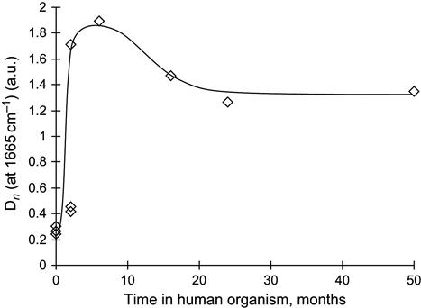
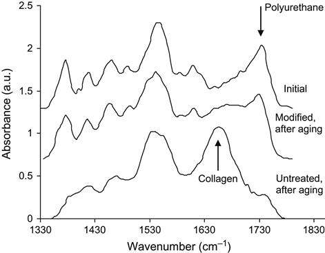
After polyurethane prosthetics are implanted, the organism initiates an immune response and surrounds the foreign body with a mostly collagen layer, in order to isolate itself from the foreign material. The collagen covering is stable and strongly attached to the polyurethane surface. The collagen cannot be removed from the polyurethane shells by washing in any detergents without the chemical degradation of proteins. The formation of a collagen covering may be detected using FTIR ATR spectroscopy. The spectra recorded from polyurethane samples after exposure to the human body contained collagen lines (Figure 9.19): different Amide I lines were seen for polyurethane and the protein. It was found that the collagen structure grew over a timeframe of 5–6 months of exposure to the human organism before stabilizing (Figure 9.20). The same collagen structure formation is observed for exposure in rat organisms (Figure 9.21). The collagen shell grows more quickly in the rat than in the human organism. The collagen structure, viewed with an optical microscope, appears as a network covering the polyurethane surface (Figure 9.22) and is detected by an antibody reaction.


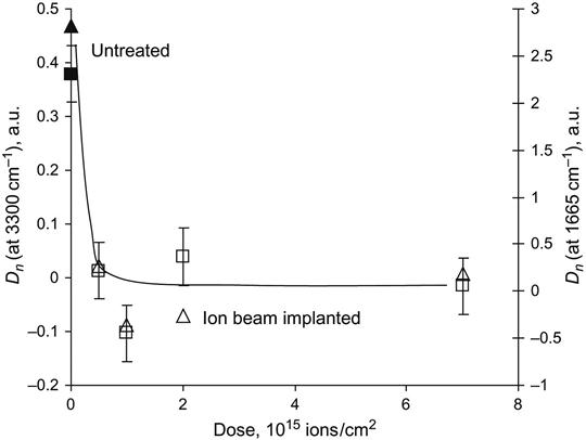
After ion beam treatment, the behavior of the polyurethane in the living organism changes significantly. FTIR ATR spectra show a significant decrease in the amount of collagen shell formed on the polyurethane surface (Figure 9.23). The amount of collagen was estimated by the relative intensity of the Amide I and Amide A lines in the FTIR ATR spectra, and it was found to decrease significantly on ion-modified polyurethane samples (Figure 9.24).
Confirming the FTIR spectra results, the absence of the collagen shell on the ion-modified surface is observed using optical microscopy (Figure 9.22). The untreated polyurethane is covered by a thick collagen shell, while the polyurethane surface modified with high-fluence ion implantation has a network of cracks, which appears to be the result of the cracking of the brittle carbonized layers formed on the polyurethane surface by the ion implantation. After ageing in the organism, the surface of the carbonized area is not covered by a collagen shell.
This behavior of the polyurethane surface can also be observed using scanning electron microscopy (Figure 9.25). The untreated surface of the polyurethane contains a collagen shell, which covers the surface. For the ion-implanted surface, the collagen is observed only at the bottom of the cracks, where areas of untreated polyurethane surface may be exposed. The surface of the carbonized layer is free from collagen. A lower-fluence ion treatment is preferable because the network of cracks is weaker, since the carbonized layer is not brittle enough for the formation of major cracks.

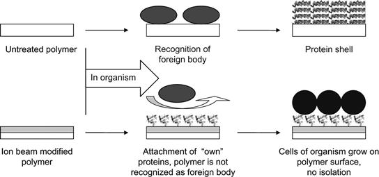
A simple schematic diagram of the polymer implantation process is shown in Figure 9.26. Untreated polymer is recognized by the immune system of the organism as a foreign body and the organism builds a wall (shell) to isolate the foreign body from the organism. In the case of the ion-modified polymer, the proteins of the organism are covalently adsorbed on the polymer surface in their native conformations. They cover the surface completely and the organism’s immune system cannot recognize the polymer as a foreign body. The organism’s cells can attach via native interactions with the adsorbed proteins, and the polymer becomes integrated into the organism’s tissues.
Polymers modified in this way could find specific applications in the human body as heart valves, artificial vessels, urea channels, mammary prosthesis, cosmetic and joint implants, etc. For example, such a modified polymer coating ingrowing into organism tissue may be a key technology for interfacing brain electrodes when the electrical connection to the neurons should be provided for an entire lifetime (80–100 years).
Together with protein absorption and cell attachment, the process of mineralization of the surface occurs [25]. Mineralization in nature is a process involving complex interactions between inorganic ions, crystals and organic molecules in an aqueous media. The organic and inorganic counterparts are continuously interacting with each other and the result is the formation of exquisite mineralized tissues with complex architecture and remarkable, microscopic designs. For polymers used as soft tissue implants in living organisms, the biomineralization process—specifically the formation of calcium phosphate deposits on the polymer surface—can induce hard structures that interfere with the success of the polymer implant. For example, calcium phosphate deposits on the internal sides of artificial vessels can obstruct the blood circulation; calcification can decrease the elasticity of soft tissue implants, such as mammary prosthetics, which brings pain to the patient. A heart valve can stop functioning after a time due to calcification of the valve walls, which make them lose their elasticity.
If after ion beam modification, the polymer surface induces biomineralization processes through the actions of the cells and proteins enveloping it, there is a danger that intense calcification processes will lead to ineffectiveness of soft tissue implants, pain and a need for removal. We have investigated the mineralization processes after ion beam modification for polyethylene, polytetrafluorethylene, and various kinds of polyurethanes, all of which are used for medical applications.
The biomineralization studies were performed in simulated body fluid (SBF), which simulates human blood plasma. The modified polymers were immersed in a supersaturated solution for 4 h at 37°C, prepared just before the samples were immersed. Two base solutions were prepared with reagent-grade chemicals. The first one consisted of NaCl (15.99 g/l), KCl (0.45 g/l), CaCl2·2H2O (0.74 g/l), and MgCl2·6H2O (0.61 g/l) dissolved in one 1itre of distilled water. The second one included Na2SO4·10H2O (0.32 g/l), NaHCO3 (0.71 g/l), and K2HPO4·3H2O (0.69 g/l) dissolved in 1 l of distilled water. The pH of the two solutions was buffered at 7.4 with trishydroxymethyl-aminomethane buffer. Before immersion of the samples, equal quantities of the two base solutions were mixed to obtain the final SBF solution. After immersion in SBF solution, the polymer samples were investigated by spectral methods and optical microscopy.
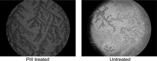
Microphotographs of the hydroxyapatite crystals on polyurethane surfaces are shown in Figure 9.27. In addition to a dendrite structure, individual crystals were seen to cover the surfaces inhomogeneously. The crystals grown over 4 h duration had similar distribution densities on the untreated and PIII-modified polyurethane surfaces. The dendrite structure of the crystals supports the view that the crystals grew from local nucleation centers, which have a low concentration on the polymer surface. When the growth of the hydroxyapatite layer was initiated by the initially nucleated crystals, the subsequent hydroxyapatite crystal growth formed a structure which indicates that further growth occurred at the interface with the initial crystals rather than with the polymer surface. Due to the high concentration of morphological and structural defects on the polymer surface after PIII modification, significant differences in hydroxyapatite crystal growth (such as additional centers) on the PIII-modified polymer surfaces as compared to the untreated polymer surfaces might be expected; however, no significant difference in hydroxyapatite crystal growth was observed. The same situation was observed for different types of polyurethanes based on polypropylene glycols and toluene diisocyanate, for commercial polyurethanes like Pellethane (Dow Chemicals), and for polytetrafluorethylene and polyethylene.
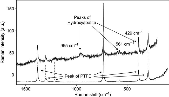
The structure of the hydroxyapatite crystals was analyzed by micro-Raman spectroscopy, which gave vibrational spectra of the thin layer of the crystal on the top of the polymer surface. Focusing on the crystals was possible due to the micrometer size of the beam and allowed us to collect sufficiently intense signals from the layer with minimum influence of the underlying polymer. The recorded Raman spectra of a PTFE surface with hydroxyapatite crystals on it show additional lines at 428.5, 561.2, and 954.4 cm−1 (Figure 9.28). The peak at 428.5 cm−1 is overlapping with a peak of PTFE at the same position. The peaks are assigned to ν2 asymmetric bending, ν4 symmetric bending, and ν1 symmetric stretching vibrations of PO4 in calcium phosphate. Generally, the ν1 stretching mode is the strongest peak in the spectrum and good crystallinity is indicated by its sharpness. The broad peak in our spectrum indicates a lower degree of crystallinity. It is known that during precipitation from aqueous solution, before the formation of crystalline hydroxyapatite, other precursor phases appear. These are amorphous calcium phosphate, octacalcium phosphate and/or dicalcium phosphate dehydrate, and low crystallinity hydroxyapatite.
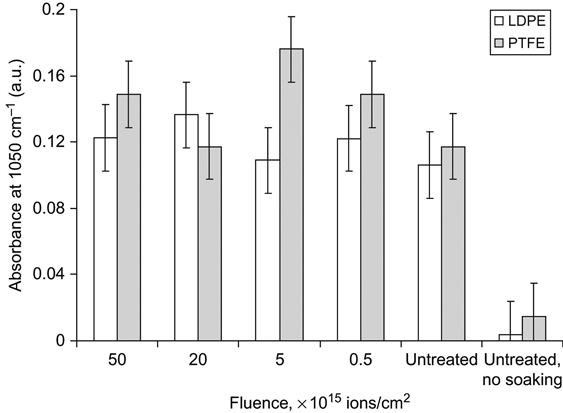
The spectral lines of the hydroxyapatite structure are also observed in FTIR spectra taken from PIII-modified polymers after immersion in SBF for 4 h (Figure 9.29). After immersion in the SBF, a weak peak at 1050 cm−1 due to the contribution of the ν3 P![]() O asymmetric stretching mode of calcium phosphates (PO4) was found in the spectra. This shows that a calcium phosphate layer precipitated on the untreated control and on the PIII-treated LDPE surface from the supersaturated aqueous solution. The relative thickness of the hydroxyapatite layers can be estimated based on the intensity of this peak in the FTIR spectra. Using Beer’s law, the absorbance at 1050 cm−1 is interpreted as proportional in value to the hydroxyapatite thickness (Figure 9.30). There is no significant difference in the thickness of the hydroxyapatite on the ion-modified and unmodified surfaces. Additionally, the amount of precipitated hydroxyapatite on polyethylene and polytetrafluorethylene surfaces is independent of the fluence of the PIII treatment.
O asymmetric stretching mode of calcium phosphates (PO4) was found in the spectra. This shows that a calcium phosphate layer precipitated on the untreated control and on the PIII-treated LDPE surface from the supersaturated aqueous solution. The relative thickness of the hydroxyapatite layers can be estimated based on the intensity of this peak in the FTIR spectra. Using Beer’s law, the absorbance at 1050 cm−1 is interpreted as proportional in value to the hydroxyapatite thickness (Figure 9.30). There is no significant difference in the thickness of the hydroxyapatite on the ion-modified and unmodified surfaces. Additionally, the amount of precipitated hydroxyapatite on polyethylene and polytetrafluorethylene surfaces is independent of the fluence of the PIII treatment.

The hydroxyapatite precipitation was measured after a short incubation of the polymer in SBF. At this early stage of precipitation, the amount of hydroxyapatite crystals depended on nucleation centers on the polymer surface. Subsequent growth of hydroxyapatite crystals did not depend on the surface properties. The equality of spectral and optical data indicating the amount of hydroxyapatite crystals on unmodified and modified polymer surfaces shows that ion implantation does not significantly affect initiation of hydroxyapatite crystal growth, which is the main cause of calcification of polymer implants in organisms. Therefore, ion implantation of polymer implants does not increase the risk of calcification.
Ion implantation surface treatment has been found useful for other specific applications in medical polymers. For example, ion implantation was applied for regulation of drug release from the polymer coating of vascular stents. The application of vascular stents in combination with angioplasty of arteriosclerotic blood vessels has become a standard technique, which is widely equivalent to bypass surgery. However, the application of a stent in the body often induces a local inflammatory reaction, proliferation of the smooth muscle cells, and neointima formation. This reaction can be reduced by the application of a stent with a polymer coating that contains anti-inflammatory or antiproliferative drugs. These drugs are released over a long time and reach effective concentrations only locally at the stented vessel wall, without achieving effective concentrations systemically.
The drug can be incorporated in polyurethane by adding it to the polyurethane solution prior to curing. Providing the drug is inactive in the polyurethane synthesis reaction, it can be inserted into a reactionable mixture of the components before the synthesis of the polyurethane. A layer of polyurethane incorporating the drug is formed after evaporation of the solvent.
For cross-linked polyurethanes that cannot be dissolved, the drug can be inserted by swelling the polyurethane in a drug solution. The drug remains in the polyurethane network after the evaporation of the solvent.
The so-called frontal process describes the kinetics of drug release from a polymer to the blood. According to this model, the release process is determined by the water front, which penetrates the polyurethane when exposed to water. The rate of the frontal process depends on the water diffusion coefficient into the polyurethane, on the maximum swelling of the polyurethane in water, and on the solubility of prednisolone in water.
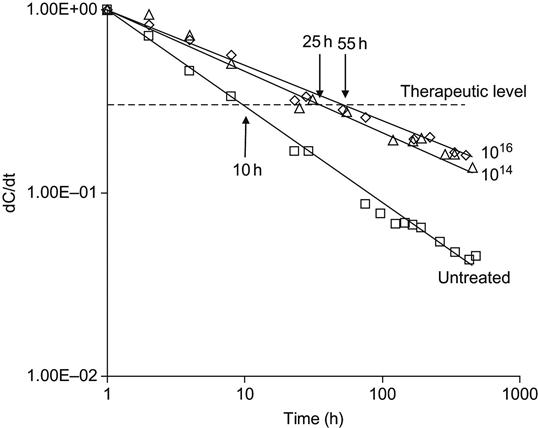
The first theoretical model of the drug release process was developed by T. Higuchi [26]. By experimental estimation, 80% of the drug is released by the frontal law and 20% of the drug is released by diffusion [27]. In general, the kinetics of drug release from a swelling polymer is very complex. It depends on the solubility and the swelling of the polymer in water, the concentration limit of the drug in water, and the distribution of the drug in the polymer [28]. For a thin coating, the kinetics of drug release are inhomogeneous, with the drug concentration high at the beginning and then decreasing sharply. Sometimes, the drug release is so quick that the concentration of the drug soon becomes lower than the therapeutic level. However, drugs usually have a toxic level of concentration in the organism. In this case, the concentration of the drug in the polymer cannot be increased high enough to stay below the toxic level in the early stages while allowing the therapeutic level to be sustained for a sufficient period of time. Therefore, the required drug concentration lies in a region with upper and lower limits determined by the toxic and therapeutic levels, respectively. To remain in this window for as long as possible, the kinetics of drug release must be as constant as possible.
We used ion beam implantation of the polymer coating to achieve a more uniform drug release kinetic. In the example, we used PIII modification of polyurethane to change the kinetics of drug release. The polyurethane was synthesized from a copolymer of polyoxytetramethylene/polyoxypropylene glycol terminated by 2,4-toluene diisocyanate and cross-linked with 3,3′-dichlor, 4,4′-diaminediphenyl-methane. After synthesis, the cross-linked polyurethane was swollen up to its saturation point in a solution of the drug, prednisolone in ethanol. After swelling, the polyurethane was dried, the ethanol evaporated, leaving the prednisolone in the polyurethane. The prednisolone release kinetics from the polyurethane to water solution was then measured using FTIR ATR spectroscopy.
The kinetics of prednisolone release from untreated polyurethane is highly nonlinear (Figure 9.31). The kinetic curve of the prednisolone release corresponds to the frontal process of drug release from a solid matrix according to the theoretical model of Higuchi [26]. The kinetics curve has a high slope in the first period of prednisolone release, and then the slope of the curve is reduced. According to the frontal process theory, the nonuniform release of prednisolone into water is observed due to rapid diffusion of prednisolone from the surface layer of the polymer. The diffusion from deeper layers of the polymer takes longer and the rate of drug release becomes lower with time.
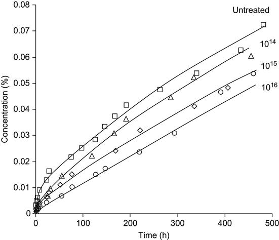
After PIII modification, the kinetic curve becomes flatter. For a high fluence of treatment (1016 ions/cm2), the kinetics curve becomes close to linear without a sharp change of slope after the first period of release.
The rate of drug release from untreated polyurethane can decrease 40-fold after 2 weeks (Figure 9.32). Therefore, the concentration of the drug in blood vessels at the location of the coated stent decreases by the same value. Prednisolone has a sufficiently narrow diapason of concentrations between toxic and therapeutic levels. If we take into account the difference between toxic and therapeutic concentrations, the period of active prednisolone concentration after inserting an untreated polymer implant is about 10 h. For a PIII-modified polyurethane implant, the period of active prednisolone concentration is 25 h, and 55 h for fluences of 1014 and 1016 ions/cm2, respectively. The prolongation of the active effect of prednisolone decreases the risk of inflammatory reactions, proliferation of the smooth muscle cells and neointima formation caused by inserting the vascular stent.
Other biological molecules—such as peptides, DNA, lipids, etc.—can be attached to the PIII-modified polymers if the active side groups of the molecules can react with radicals in the ion-treated polymer surface layer. An example of DNA attachment is presented in Figure 9.33. The two-strand DNA molecules were not attached to PIII-treated polystyrene sheet. This is due to the fact that the external sides of the DNA molecule contain a phosphate residue, which is not reactive with the radicals in the treated polymer surface. However, attachment was achieved when the strands of the DNA molecule were partially separated, making the monosaccharide or nucleobase residues accessible to the polymer surface. Therefore, the spectrum of the modified polystyrene does not show DNA lines when the polystyrene is incubated in the two-strand DNA solution at room temperature, but does show DNA lines when the DNA solution is heated up to 90°C. When the DNA strands are separated completely or partially by heating, the hydrocarbon groups of the DNA residues can be covalently anchored to the ion-modified polystyrene surface. Thus single-strand DNA, as well as nucleabases and saccharides can be attached in this way to a surface.