Polymerization of liquid polymer matrix in free-space environment
The problem of a lengthy stay in space is compounded by the size and mass of space construction, and its delivery from Earth surface to Earth orbit. The space construction sent to Earth orbit is limited by the launch vehicle. The problem of making large-size constructions can be solved by curing of fiber-filled composites with polymer matrix in free space under high vacuum, cosmic rays, atomic oxygen flux, microgravity, meteorite flux and temperature variation. The fabric impregnated with a long-life matrix (prepreg) is prepared in terrestrial conditions, folded, and sent into free space. After unfolding a curing reaction of polymerization is initiated. After polymerization, the durable frame can be fitted out with air under normal pressure. A matrix composition curable in high vacuum can be found. The cosmic rays initiate and accelerate the curing reaction. The strength of the composite cured in space can be sufficient to build large (100×10×10 m3) frames after one carrier launch.
Keywords
polymerization in space; prepreg; composite; free-space environment; space flight
Space flight is wonderful accomplishment for our civilization. Humankind has a 50-year history of space flights. However, up to now, these have been limited to near-Earth space. The International Space Station (ISS) is a bigger version of the Spacelab, Salut, and MIR stations, and we await the next new step in space exploration.
Recently, businesses and governments have shown a renewed interest in space activity. This is caused by new technologies that present new possibilities for industry in specific space environments. The private space orbital carriers such as “Spaceship One” or Space X Dragon and the first private space hotel from Bigelow Aerospace have been launched. On the other hand, the space environment is a source of new possibilities for businesses: microgravity for biotechnology, extra-pure vacuum for semiconductors, and mines on other planets. The National Aeronautics and Space Administration (NASA), the European Space Agency (ESA), the Russian Space Agency (RSA), the National Space Development Agency of Japan (NASDA), and the Chinese National Space Administration (CNSA) have expressed interest in large space constructions that can pave a new way for the space industry.
The problems of a lengthy stay in space, deep space flights, orbital plant, and Moon or Mars colonies are compounded by the size and mass of space construction, and its delivery from Earth surface to Earth orbit. However, the size and mass of space construction sent to Earth orbit are limited by the size of the launch vehicle.
The problem of making large-size constructions can be solved by using the technology of the polymerization of fiber-filled composites and a reactionable matrix applied in free space or on another space body when space construction takes place over a long period of time. For the creation of the construction frame, the fabric impregnated with a long-life matrix (prepreg) is prepared in terrestrial conditions and, after folding, can be kept on board a spaceship after launch. In due time, the prepreg is sent into free space and unfolded by, for example, inflating. Then, a reaction of matrix polymerization takes place. After polymerization, the durable frame can be fitted out with air under normal pressure. Next, the crew can carry out work in the frame without space suits, to build a station, space plant, space hotel, or greenhouse, for example, fitting the frame with apparatus and life-support systems.
In this case, frame size and the form of future space construction are not limited by the ability of modern space carriers. The launch of a bulky frame for a large-size space station, solar cell panel, or antenna needs one carrier, reducing any form of risk at lift-off. The creation of the frame does not require dangerous and complicated procedures to join separate blocks in orbit and provides otherwise extremely difficult hermeticity of the joints.
However, the technology of polymerization was not used for creation of space construction. The problem of polymerization in free space is connected with specific conditions of the free-space environment for polymer materials. The conditions of free space have a great destructive influence on polymer materials, especially on the liquid polymer matrix. In free space, the composite material is treated with a high vacuum, sharp temperature changes, plasma of free space formed by space rays, sun irradiation and atomic oxygen (AO) (on low-Earth orbit, LEO), micrometeorite fluency, and microgravitation [1–8]. Free-space conditions can be simulated on Earth in a high-vacuum chamber, plasma discharge, and ion beam implanter. In this chapter, we consider the polymerization processes in simulated free-space environment conditions of LEO and geostationary earth orbit (GEO), which are of most interest for space constructions.
Vacuum
The altitude of LEO varies from 90 to 1000 km. The orbits for most space flights vary between 300 and 400 km in altitude. The pressure of residual atmosphere on an altitude of 300 km is reported as 10−3–10−5 Pa. The pressure near the spaceship or space construction depends on time from launch. During flight, desorbing gases, venting trapped volumes, releasing dust and ice particles can increase the pressure near a new space construction. By experimental observation, the pressure can vary from 10−5 to 10−3 Pa, depending on the time of flight, sun irradiation, local configuration and spaceship materials, and activity of the engine. Even at a distance from Earth of about 36,000–42,000 km, corresponding to a GEO mission, the pressure would not equal 10−9–10−11 Pa. Due to continuous evaporation, the pressure near a satellite or spaceship would be significantly higher.
The temperature in space experiments in Earth orbits usually varies from −150°C to +150°C and even 200°C. The combination of high vacuum and high temperature dramatically influences the evaporation process of polymer materials. The main effect of such a vacuum is observed as evaporation of low molecular mass fractions. The rate of evaporation into a high vacuum is described by Langmuir’s formula:
(Eq. 11.1)
where M is the molecular mass of vapor, T is the temperature (K), and P is the equilibrium vapor pressure of fraction from the Klausius–Klapeyron equation [9]. With a lengthy vacuum action, the stoichiometry of low-weight molecular components in the matrix can be changed [10].
Space plasma
Space plasma is created by the fluency of galactic and sun protons, electrons, neutrons, and heavy particles with wide diapason of energy from some eV to hundreds of MeV; infrared, visual, ultraviolet, and vacuum ultraviolet (VUV) photons and X-ray/γ-photons. On LEO, the fluence of AO is added as a more significant factor in comparison with other factors of space plasma on GEO [11]. The main destruction factors of space plasma for hard polymer materials by space experiments and laboratory experiments are thermal AO, high-energy electrons and protons flows, VUV irradiation, and X-ray irradiation. The parameters of space plasma in space construction depend on space weather: sun activity, Earth atmospheric events, day/night time, parameters of space orbit, Earth position, and space construction conditions. Measurements in various space experiments and flight missions show that the space plasma parameters can vary 100 fold in response to the range of combinations of all of the above factors.
Atomic oxygen
The experiments on LEO with degradation of polymer materials show that the AO is the main factor limiting the exploitation time of materials. The estimation of average AO flux on LEO (near 300 km altitude) during real experiments with polymer materials gives 2.88×10¹³ at/cm2/s average value [11], 3.88×10¹³ at/cm2/s in Long Duration Exposure Facility mission [12], 1014 in Materials International Space Station Experiment (MISSE) mission [13], 5×10¹⁴ at/cm2/s theoretical value, and 4.3×10¹⁴ at/cm2/s on Kapton equivalent for Evaluation of Space Environment and Effects on Materials (ESEM) mission [14], 5×10¹³ at/cm2/s [15] and 1012–1015 at/cm2/s [16] for ESEM mission too, 1013–015 at/cm2/s [17]. In the Hubble mission (595 km altitude), the AO flux equaled 6.86×10¹¹ at/cm2/s. The flux of AO varies due to sun activity, season, position, longitude/latitude and altitude of spaceship, variations in Earth atmosphere, and outgassing processes of spaceship materials. The model approximation developed in Ref. [18] shows an AO flux of 2×10¹¹ atoms/cm2/s at 400 km altitude.
VUV irradiation
VUV irradiation is part of the solar spectra of irradiation. The intensity of VUV light is low, but the effect of VUV light on polymers is significantly higher than visual and UV light. At LEO, the level of VUV light was estimated of about 4×10¹¹ photons/cm2/s for a 121.6 nm wavelength [19]. The sun irradiation density corresponds to 0.75 μW/cm2 in a VUV diapason of 100–150 nm wavelength [20] and 11 μW/cm2 in a UV diapason of 200–300 nm wavelength [21].
A number of gas-discharge sources are used for the simulation of solar VUV light in laboratory experiments. The hydrogen lamp generates a line at 121 nm in a VUV diapason. The deuterium lamp generates continuous spectra in a diapason of 115–400 nm. Krypton and argon lamps are also used. Usually, the irradiation intensity of some units of solar VUV activity from lamps is used for rapid ageing of polymers. The VUV factor is significant for polymers at LEO and GEO missions.
X-rays
The level of X-rays in Earth orbit equals 2.3×10⁻⁹ W/cm2 for a 1–8 Å wavelength and 1.43×10⁻¹⁰ W/cm2 for 0.5–4 Å wavelength [22]. The majority of flux from x-rays is directed from the sun, with less from other stars.
The simulation of x-ray irradiation was made with a Cu Kλ line source with electron excitation energy lower than 60 keV. The intensity of x-ray irradiation was 1.3×10⁻³ W/cm2.
High-energy particles
The energetic spectrum of electron and ion fluxes at LEO and GEO is sufficiently complex. The energetic spectrum and flux of charged particles depends on the kind of particle, altitude, longitude/latitude, seasons, and sun activity. The energy of charged particles varies in diapason from 0.1 eV to some GeV. In laboratory experiments, some theoretical models are used for the analysis of effects in materials generated by charged particle flows. The density of electrons at a LEO altitude of 400 km equals 105 e/cm3 (night side) and 106 e/cm3 (day side) [11], with energy of 0.1 eV [19]. The electron flux in a GEO mission equals 109 e/cm2/s for electrons, with energy of 0–12 keV [23]. The electron density in a GEO mission of 1.12 e/cm3 at average energy of 1.2×10⁴ eV and ion density of 0.236 ion/cm3 with average energy of 2.95×10⁴ eV is used for the simple analysis of plasma in GEO missions [24]. The most frequent ions are hydrogen ions (90%). The other 10% of ions consist of all elements.
Laboratory simulation of high-energy particles is made on the basis of accelerators of electrons and ions. The energy of electrons in Earth laboratory experiments [21,25,26] varies from 20 keV to 2 MeV. The energy of ions in experiments varies from 40 keV [25] to 2 MeV [21]. Principally, the electron and ion beams are used for the simulation of the GEO space environment on polymers.
Temperature variations
The total solar irradiation from the Earth to the sun equals 1362–1367 W/m2 [11]. The solar irradiation level depends on the season (position of Earth on solar orbit) and it can vary from 1316 W/m2 at minimal solar energy flux (summer solstice) to 1428 W/m2 at maximal solar energy flux (winter solstice) [18]. The level of de-irradiation of sunlight by the Earth’s surface and its atmosphere equals 240 W/m2. Temperature changes in the spaceship frame depend on its orientation to sunlight, absorption and emission indexes of the frame surface, and internal heat sources [27]. The real temperature of the frame surface in LEO can vary in wide diapason: −56°C÷+77°C [28], −90°C÷+120°C [29], −100°C÷+200°C [30] and [22], and −150°C÷+150°C [31]. For far space missions such as the Next Generation Space Telescope mission (halo orbit, 1.5×10⁶ km from Earth), the estimated temperature equals −223°C÷+122°C [32].
In LEO, the surface of the spaceship is under thermal cycling for a period of about 90 min due to sunlight and Earth shadow. In GEO, the surface temperature of the spaceship depends only on orientation and rotation of the spaceship in relation to sunlight. Thermal cycling has a destructive effect on polymer materials. The analysis of temperature changes at rotation of the frame to the sun showed that the appearance of a sharp temperature gradient in the space station frame during curing time is possible. The appearance of a temperature gradient in curing plastic leads to the formation of internal stresses in the cured frame after decreasing or changing the sign of the temperature gradient [33].
Microgravity
On LEO and GEO missions, a spaceship exists in microgravity conditions. The level of gravity is two orders lower in comparison with gravity on the Earth’s surface. The gravity level on the spaceship depends on acceleration conditions of the spaceship, light pressure, gravitation gradient, movements of the crew, docking, etc. The polymerization of acrylamide gel was made during space flight on the Shuttle [34] and on the “Mir” space station [35,36]. Polymerization was held inside the spaceship, and the influence of microgravity on polymerization process was investigated [37]. Other factors of space environment were excluded. In addition, the influence of microgravity on the polymerization process was studied in experiments of downfall at the Drop Tower of the Bremen Center of Microgravity [38] and during the flight of sounding rockets by investigators from the University of Southern Mississippi [39].
The influence of microgravity on polymerization is based on the exclusion of convection and sedimentation processes in the curing polymer [1,40,41]. Under microgravity conditions, a frontal polymerization process and creation of highly homogeneous polyacrylamide gel were observed [40–43]. In high-filled polymers, such as epoxy composite materials, the microgravity should not influence the polymerization process. However, for tall constructions of prepreg, there is the limitation of high dimension due to flow of liquid resin in the Earth’s gravity field. By estimation, the limit in height for constructions with liquid resin on Earth is about 3 m. In microgravity in LEO and GEO, the limit for large-size construction dimensions due to flow of liquid resin should be absent.
Meteorite fluency
Meteorite fluency leads to the mechanical destruction of material. In the case of liquid polymer, the influence of meteorite fluency is weaker than for a hard polymer, because a collision of meteorite particles with the surface of liquid polymer does not lead to crack formation. Erosion of polymer at meteorite fluency corresponds to 0.1 nm/year in far space and 20 nm/year on LEO [9].
The conditions in the free-space environment are extreme for solid polymer materials. Destruction of polymers in free space was studied on many occasions, including real experiments outside the spaceship in LEO and GEO, and in laboratory modeling experiments of space action on Earth [13,17,19,20,26,29,31,32,44–74]. These studies showed that destruction of epoxy composites, HDPE, LDPE, Kapton, Teflon and FEP Teflon, Tedlar, Mylar, fluorinated polyimides, polyurethanes, polysulfone, and others during flight in LEO is connected with plasma action of AO with low kinetic energy. The basic results of destruction are loss of mass, dehydration, formation of an amorphous carbon layer, formation of cracks and craters on surfaces, and a decrease in the durability of polymer.
In laboratory experiments, the influence of separate space factors on polymers was studied in more detail. The conditions of the simulated free-space environment used for polymer degradation in the laboratory can be overviewed in Table 11.1. The main influence at LEO mission is connected with AO and VUV actions. The main influence at GEO mission is connected with VUV, electrons, and ion erosion actions. The AO, electrons, ion fluxes, and VUV intensity depend on sun activity and spaceship mission conditions. NASA Guidelines with “The Space Environments and Technology Archive System” at Langley Research Center (LaRC), Boeing Database, and Canadian Database can be used for simulation of space orbit conditions during virtual space missions on hard polymer materials.
Table 11.1
Free-space environment simulated conditions for experiments on polymerization
| Factor of space environment | LEO | GEO |
| Temperature | −150 … +150°C | −150 … +150°C |
| Vacuum | 10−1 … 10−3 Paa | 10−1…10−3 Pab |
| Atomic oxygen | 1012 … 1015 atom/cm2/s | – |
| UV light | 0,75 μW/cm2 at 100–150 nm wavelength | 0,75 μW/cm2 at 100–150 nm wavelength |
| 11 μW/cm2 at 200–300 nm wavelength | 11 μW/cm2 at 200–300 nm wavelength | |
| X-rays | 10−3 W/cm2, Cu Kα, 60 keV | 10−3 W/cm2, Cu Kα, 60 keV |
| Electron beam | 109–1012 electron/cm2/s at 40 keV energy | 109–1012 electron/cm2/s at 40 keV energy |
| Proton beam | 105–109 proton/cm2/s at 40 keV energy | 105–109 proton/cm2/s at 40 keV energy |
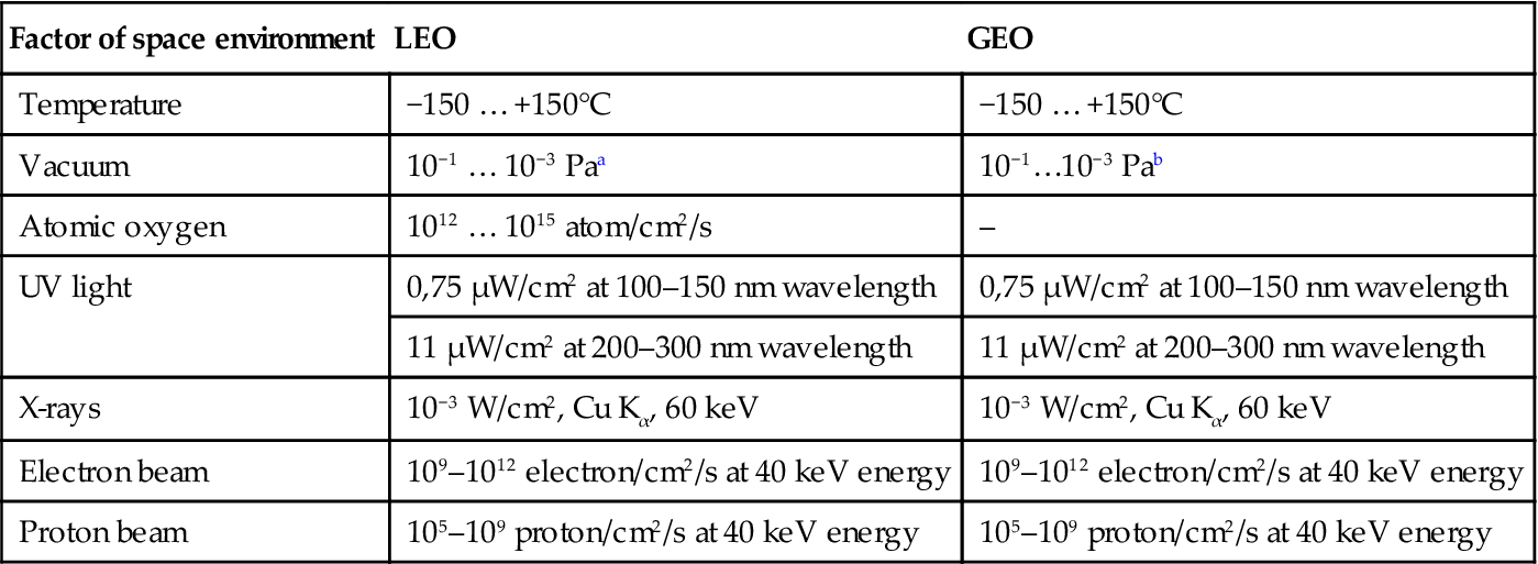
aThe variation of the values corresponds to the variation of solar activity with time.
bThe pressure of 10−9…10−11 Pa was estimated for GEO mission without any evaporation from spacecraft material. Real pressure is higher (10−3…10−5 Pa). The pressure of lower than 10−3 Pa for high evaporated substances like polymers is not achieved by known vacuum pumps. However, the pressure of 10−1…10−3 Pa is lower than an evaporation pressure of known monomers and oligomers for polymer matrix. Therefore the pressure of 10−1…10−3 Pa in laboratory experiments is adequate to real pressure at LEO and GEO missions.
The effects of degradation can be observed using the following methods: optic and electron microscopes and AFM reveal an increase in the roughness of the polymer surface; XPS spectroscopy reveals oxidation of the surface layer; and mechanical and thermo-mechanical methods show a decrease in durability and an increase in modulus and Tg. Comparison of polymer degradation results in real free-space experiments and in simulated free-space experiments shows similar changes of structure and characteristics of polymers.
The polymerization processes in liquid composition under real-space conditions during space flight was not investigated yet. In general, the polymerization process in epoxy composition includes a chemical reaction of polycondensation, when an epoxy ring of the macromolecule opens under the action of a catalytic agent or active group of hardening agents with the formation of chemical bonds between macromolecules. During curing, the molecular mass of components increases up to the formation of a “physical” or “chemical” polymer network. The viscosity increases slowly at the first period of reaction and quickly at the second period of reaction. The kinetic process of reaction with temperature corresponds to Arrhenius’s law, with acceleration and deceleration stages of reaction.
Typically, long-lifetime epoxy compositions are considered for space application in deployable structures. The composition must be stable under transportation conditions. The polymerization reaction must be initiated at the right time in space when the construction is deployed. The curing of epoxy resin can be initiated by the heating of a reactionable mixture. This is the usual way for initiation of chemical reactions. The lifetime of such systems depends on temperature. For a long lifetime, the mixture must be saved at low temperature and/or heated to high temperature for polymerization. In this case, the thermal regime of construction is important to manage the polymerization reaction in space.
The polymerization reaction can be initiated by irradiation of UV or visual light. The special UV photoinitiators are inserted into epoxy resin. The UV photoinitiator initiates the curing reaction under UV light. The lifetime of such a system is very long and depends on the intensity of light at storage. The polymerization process in epoxy composition during UV curing corresponds to the frontal process of moving the polymer/oligomer boundary into bulk layers of material.
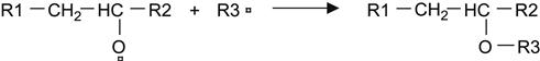
Let us consider a polymer matrix, which can be used for the polymerization process in a free-space environment. One of the common epoxy compositions is based on amine hardening agent. Polymerization reaction in modeling composites is carried out with amine hardening agents of triethanolamine (TEA) or triethylenetetramine (TETA). With TETA, the condensing reaction leads to the formation of hydroxyl groups and secondary amine groups. This reaction is sensitive to stoichiometric ratio of components, and this reaction has a wide application for the synthesis of epoxy matrix in carbon- and glass-reinforced composites. The reaction with TETA hardener agent proceeds during 6–8 h at room temperature, which is useful for modeling studies, and few minutes at high temperature, which is suitable for space application.
 (11.1)
The reaction of epoxy resin with a TEA hardening agent proceeds at a high temperature, and the composition can be stored in the liquid state over a number of days at room temperature. This reaction is useful for modeling studies when a liquid-reactionable composition should be used for transportation or measurements for a long time before curing. The reaction of epoxy resin with TEA was used for modeling the polymerization process under vacuum and plasma treatment. The polymerization reaction in this composition is shown here:
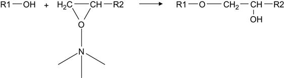 (11.2)
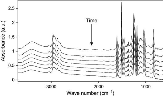
The kinetics of the polymerization reaction is well observed by FTIR and Raman spectroscopy. An example of FTIR spectra of epoxy resin with a TETA hardening agent during curing is shown at Figure 11.1. The intensity decrease of the 915 cm−1 line shows the decrease of the epoxy group concentration during reaction. The intensities of lines at 862, 971, 1078, 1347, 1429, 3000, and 3056 cm−1 related to epoxy and ether groups also show the reaction kinetics. Typically, the 915 cm−1 line intensity is used for quantitative analysis of reaction.
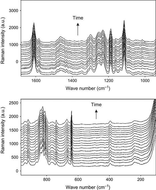
Raman spectra of the reaction mixture are useful for reaction analysis of thick composite samples in experiments with vacuum, plasma, and ion beam treatment when thick composite samples cannot be analyzed by FTIR spectra. In this case, for Raman spectra the sample is irradiated locally in a small point, with diameter of the laser beam. Raman spectra of epoxy resin with a TETA hardening agent during curing are shown in Figure 11.2. Analysis of reactive groups can be done by intensity of lines at 677, 770, 799, 987, 1053, 1134, 1160, 1260, 1430, and 1482 cm−1. Time dependence of these lines’ intensity and FTIR spectra are used for calculating the stage of the curing reaction in the epoxy matrix.
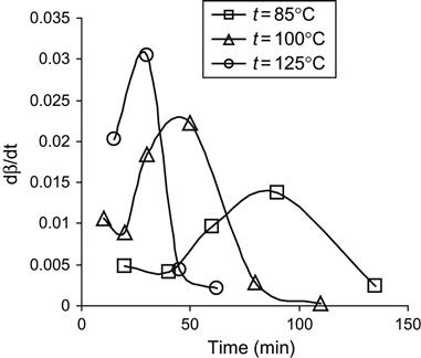
The analysis of the polymerization reaction of epoxy resin and the TEA hardening agent at different temperatures is presented in Figure 11.3. The dependence of reaction stage on time corresponds to the type of polymerization reaction of the second order with autocatalyst and autoinhibition:
(Eq. 11.2)
where the β is the stage of polymerization, which is calculated from intensity of active group lines in FTIR or Raman spectra; and the k1, k2, and α are constants of the polymerization reaction.
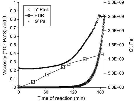
The curing kinetics is measured using the viscosity of the mixture of epoxy resin and the hardening agent. With time, the viscosity of the reactionable mixture increases, which corresponds to the polymerization reaction. The matrix viscosity increase with time of the reaction is responsible for an increase of modules of filled composite. The curves of the epoxy group concentration (by FTIR and Raman), viscosity of mixture and modulus of composite with time show the kinetics of polymerization (Figure 11.4).
The vacuum of free space in LEO and GEO orbits (10−3…10−5 Pa) is too high in comparison with vapor pressure of all components of the polymer matrix (range of 10–1000 Pa). In high vacuum, the stoichiometric ratio of active components in the liquid matrix changes due to different evaporation rates of low-molecular-weight components. The evaporation process of separate components depends on the vapor pressure of components, diffusion coefficients of components in the polymer matrix, thickness of the matrix layer, temperature, and pressure of environment. In the case of fractional constitution of the epoxy resin and hardening agent, the low-weight fractions can quickly evaporate and the chemical activity of the mixture can decrease with time. The deviation of stoichiometric ratio and the decreasing of chemical activity of the matrix can cause the polymerization reaction to stop. The evaporation of liquid components can decrease the polymer matrix contamination in the composite, and a ratio of matrix/fiber contamination can move away from the optimal ratio for expected properties of the composite.
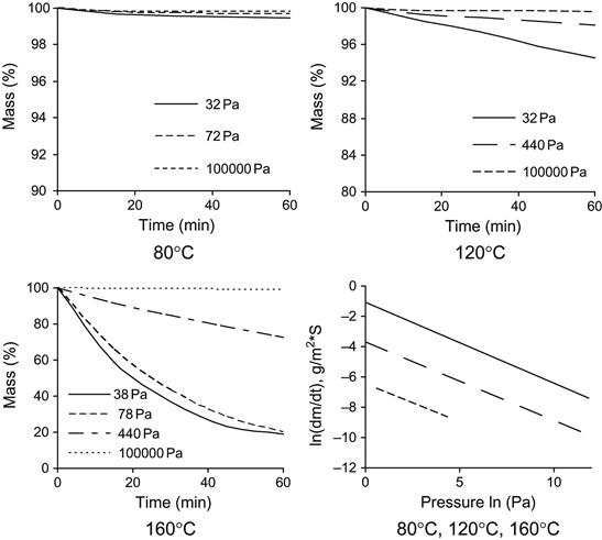
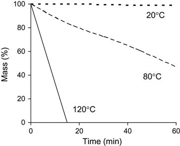
The evaporation rate of individual polymer matrix components depends on pressure and temperature. An example of the mass loss of epoxy resin based on Bisphenol A (average MM=374) is presented in Figure 11.5. An increase in temperature accelerates the evaporation process. A decrease in pressure increases the evaporation rate. High evaporation rate is observed for TETA and TEA hardening agents (Figure 11.6). TETA evaporates at room temperature in a vacuum. At high temperature and low pressure, TETA can be boiled. The evaporation of TEA is observed only at high temperature and low pressure, but the both TETA and TEA rates of evaporation are higher than for epoxy resin.
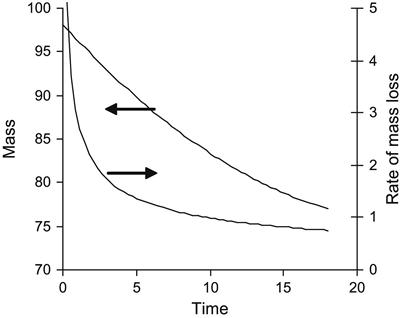
The evaporation kinetics of epoxy resin is complicated. The resin consists of a number of fractions with different pressures of vapor and different rates of evaporation. The kinetics rate of epoxy resin evaporation decreases with time. At first, light fractions evaporate with a high rate of evaporation, and then heavy fractions evaporate with a low rate of evaporation. A simulation of the evaporation process from a mixture of components with different evaporation rates is presented in Figure 11.7.
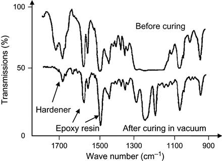
If evaporation of a hardening agent is strong enough, the stoichiometric ratio becomes broken during polymerization under vacuum. Experimentally, such a situation is observed for an epoxy matrix based on epoxy resin with an isomethyl-tetrahydro-phthalate anhydride hardening agent (Figure 11.8). The polymerization reaction with anhydride hardener proceeds at a high temperature of 130–150°C. However, the evaporation of anhydride is intensive at low temperature and sufficiently high pressure. At low pressure and high temperature corresponding to real-space conditions, the evaporation of anhydride proceeds even with boiling. Therefore, the hardener evaporates more quickly than does the epoxy resin. Before the reaction, the spectrum shows lines of epoxy resin and hardener. After exposure under vacuum and temperature of polymerization, the spectrum no longer contains hardener lines. The hardener has been completely evaporated during reaction. The epoxy groups have not been spent and the reaction is stopped. The matrix remains soft.
Intensive evaporation can cause a boiling effect of the liquid, as it is observed in a simple experiment with water under low pressure. When a liquid composition is boiling, the bubbles are formed. After polymerization, a hard foam structure of the composite is observed. This gives a random structure of the composite material cured under vacuum and breaks the mechanical properties of the composite. To prevent breaking the composite, any boiling and foaming effects in the liquid matrix during polymerization reaction in a vacuum must be completely avoided.
The measurements of evaporation rates showed that the evaporation process is significant for individual components of polymer matrix even at higher pressure than in free space. The evaporation rates of epoxy resin are significantly lower than for TETA and TEA hardening agents. An exclusion of the evaporation of liquid polymer matrix in free-space environment is impossible. However, the negative effect of evaporation can be decreased or excluded.
At LEO missions, the AO fluence is the most significant factor of the free-space environment on construction materials. During exposition of polymer in AO flow, the processes of chemical reactions create the etched oxidized surface layer of polymer. The AO effect is associated with other high-energy particles (mostly electrons, protons and alpha particles) from the sun and galaxies. A beginning period of liquid composition in space could be critical, due to small molecules of epoxy resin and hardening agent. At this time, the bombarding by high-energy particles breaks the chemical bonds of the polymer backbone, and short separated parts of destroyed molecules evaporate quickly. With time of the curing reaction, the macromolecules become heavier and the break of the backbone does not lead to catastrophic degradation and evaporation of the polymer. Therefore, the first period of polymerization reaction is very important for erosion activity under AO and other particles fluence. On the other hand, the high-energy particles influence on the polymerization reaction by the way of formation of free radicals and movement of treated layers into bulk layers of liquid composition. In this case, the macromolecules with free radicals can take part in polymerization reactions with the formation of additional crosslinks in the composite. Such effect of high-energy particles on curing polymers can be simulated in plasma and ion beam.
The VUV and electron flow penetrating the polymer can break the chemical bonds and generate free radicals. Such free radicals can take part in the curing reaction and increase the curing rate. Taking into account the nonhomogeneity distribution of intensity of VUV light and electron density in polymer, the behavior of the polymer matrix during curing depends on the thickness of the matrix and the presence of filler. A combination of different free-space environment factors gives an extremely complicated picture of the curing processes in the LEO environment. Therefore, the actions of AO, VUV, and electron beam—together with the mixing processes of the liquid matrix on the kinetics of the curing reaction—cannot be predicted by experiments with separate factors. In this case, a real-space experiment has a great significance for understanding of space plasma environmental effects.
At GEO missions, the high-energy electrons and ions flows with VUV irradiation are the main factors of free-space environment for polymer degradation. For high-energy particles, the penetration depth into the polymer is much higher than the AO. The structure changes of the polymer matrix in bulk layers are more likely in this case. The flux of high-energy particles is lower than AO. During high-energy electron and ion irradiation, the free radicals can influence the kinetics of polymerization, as in the LEO environment. The polymerization process of epoxy composition in the free-space environment contains: the chemical reactions of epoxy groups with hardening agent and epoxy groups with free radicals; reactions between free radicals and free radicals with virgin macromolecules; convection processes depending on viscosity of the composition; carbonization processes caused by high-energy particles with processes of etching; and component evaporation and diffusion from surface layers.
The action of space plasma is very significant at the first stage of polymer presence in space, when the composition is liquid. After polymerization, the composition becomes hard and the degradation process under space plasma proceeds as expected, as it was studied in real-space experiments. Therefore, the curing of the polymer matrix initially from liquid to solid states under space plasma environment is a key for the development of the polymerization technology of space constructions.
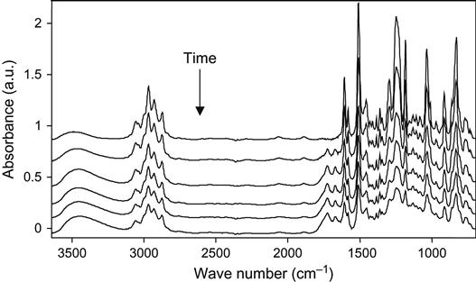
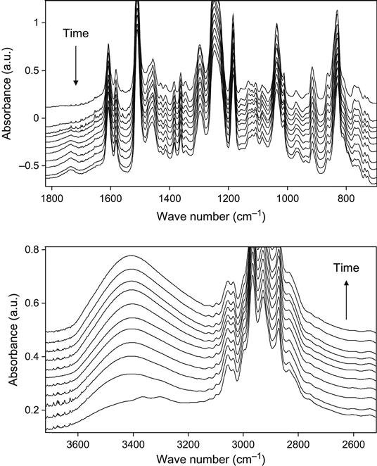
The influence of high-energy particles on uncured epoxy matrix is observed in plasma experiments with liquid epoxy resin. The liquid epoxy resin without hardening agents was put on KBr pellets and treated with oxygen plasma at low pressure. The FTIR spectra of the resin show the changes after exposure in plasma discharge (Figure 11.9). The optical density of the line at 1247 cm−1 of the ether group; at 1610 and 1510 cm−1 of the aromatic ring of resin; 1455, 1385, and 2966 cm−1 of the methylene groups; and 3450 cm−1 of the hydroxyl groups decreases with plasma exposure time. These spectral changes correspond to the etching process of epoxy resin in plasma. With the increase of plasma treatment time the thickness of the epoxy resin layer decreases and the optical density of all spectral lines of the epoxy resin decreases as well.
If spectra are normalized on the thickness of the resin layer, it is observed that the 1730 cm−1 line of the carbonyl group appears, and the optical density of this line increases with an increasing in time of the plasma treatment. The increase in this line intensity corresponds to the oxidation processes in epoxy resin under plasma action. This line has a complex profile that corresponds to different carbonyl-containing groups in resin macromolecules after plasma. These are carboxylic acid, ester, and aldehyde groups. These groups appear under plasma action during destruction processes of macromolecules of resin. In the hydroxyl stretch vibration region, the optical density at 3450 cm−1 increases after plasma treatment. The line is wide and interpreted as a stretching vibration line of the hydroxyl groups, which appear as a result of resin destruction in plasma as well. The increase in line width in all spectra regions is observed for a long time during plasma treatment.
Similar spectral changes are observed in spectra of cured epoxy resin treated with plasma (Figure 11.10). The epoxy resin with TETA hardening agent was used. However, the changes are weaker than in liquid resin at the same plasma conditions and time of treatment. The decrease in line intensity observed in all spectra corresponds to etching of the resin with time of plasma treatment. The rate of spectral changes in cured resin is less than for liquid resin. The weak line of the carbonyl group stretching vibrations at 1730 cm−1 is observed in the spectra of plasma-treated hard resin. The weak increase in absorbance in the region of the hydroxyl group stretch vibrations is also observed. These spectral changes are observed at the beginning of plasma treatment, and after a lengthy time of plasma treatment the intensity of carbonyl and hydroxyl group lines does not increase. Such spectral changes in hard resin correspond to well-known data on modification of polymers in low-pressure plasma. The weak spectral changes are explained by surface character of plasma modification: the thin surface layer of the resin is modified and etched during plasma treatment. The bulk layer of resin is not changed during plasma treatment.
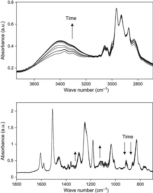
Similar changes in the spectra of liquid epoxy resin with hardening agent are observed during plasma treatment (Figure 11.11). In these experiments, the reactionable mixture of epoxy resin and hardening agent was placed on KBr pellets immediately after preparation. The decrease in line intensity in all regions of spectra shows the etching processes of composition as in the spectra of liquid and hard epoxy resin. In normalized spectra, the chemical structure changes are observed. By the stretching of vibration lines of the carboxyl and hydroxyl groups at 1730 and 3450 cm−1, the oxidation process is observed during plasma treatment. The reaction of polymerization is observed by the intensity of the epoxy ring vibration lines at 915 and 860 cm−1; by the intensity of stretching vibrations lines of the methyl group near the epoxy ring at 3000 and 3057 cm−1; by the intensity of ether group vibration lines in the C![]() O vibration region at 1260, 1120, and 1107 cm−1; and in the O
O vibration region at 1260, 1120, and 1107 cm−1; and in the O![]() H stretch vibration region at 3407 cm−1. The observed decrease in the epoxy ring line intensity and the increase in the hydroxyl line intensity correspond to the reaction of the polymerization of epoxy resin.
H stretch vibration region at 3407 cm−1. The observed decrease in the epoxy ring line intensity and the increase in the hydroxyl line intensity correspond to the reaction of the polymerization of epoxy resin.
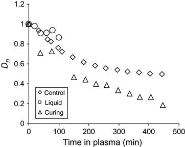
The received spectral data were used for quantitative analysis of reaction kinetics in the plasma-treated sample and in the control samples. The kinetics of the etching process was observed by the optical density of a stretch vibration line of aromatic ring at 1510 cm−1. The form of this line does not change during etching, and the aromatic ring does not take part in the reaction of polymerization. In Figure 11.12, the dependence of the aromatic ring line intensity is presented for epoxy resin in liquid state, in cured state, and during polymerization. The etching rate of cured resin is lowest, which corresponds to the highest stability of hard resin at plasma treatment. The etching rate of liquid resin is highest, which corresponds to lowest stability of liquid resin in plasma. The etching rate reflects the ability of resin macromolecules to be cut on separate low molecular parts under the action of plasma particles, and to be evaporated into the vacuum of the plasma chamber. For liquid resin with initial short macromolecules, the rate is highest due to the possible formation of short molecules after breaking the polymer chain under the action of plasma particles. In hard resin, the macromolecules are connected by crosslinks and the appearance of the short molecules due to plasma action needs a certain amount of breaking of the polymer chain.
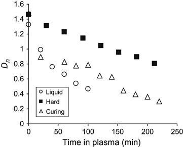
During polymerization, the etching rate of the reactionable mixture decreases with time. Initially, the rate of mixture is close to the rate of liquid resin, and during the polymerization reaction the etching rate of the mixture is equal to the cured resin. For the resin during polymerization, the etching rate depends on the coordinate of reaction. An average rate of etching for liquid and hard epoxy resin was determined by a linear approximated curve of the optical density of the 1510 cm−1 aromatic ring line in FTIR spectra. On average, the etching rate for liquid resin is 0.083 µm/min, for polymerizing resin the rate equals 0.040 µm/min, and for hard resin the rate equals 0.038 µm/min.
The absorbance of the normalized spectra was used for analysis of chemical structure changes in epoxy resin during the reaction of polymerization under plasma action. In Figure 11.13, the absorbance of the epoxy ring line at 915 cm−1 is presented for resin during curing in plasma and during curing under atmospheric conditions (control sample). In addition, the absorbance of the epoxy ring line for liquid resin without hardening under plasma action is also shown. The kinetic curve of the control sample corresponds to the kinetics of the second-order reaction with acceleration and deceleration stages. The kinetic curve for resin cured in plasma goes deeper than the curve of the control sample. Also, some decreasing of epoxy ring line intensity is observed for liquid resin without hardening agent that is treated in plasma. The decreasing of intensity can be caused by the interaction of the epoxy ring with products of plasma destruction. The reaction of the epoxy group with free radicals generated by plasma in the surface layer of epoxy resin is proposed in Ref. [7]:
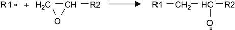 (11.3)
 (11.4)
Another way is the reaction of the epoxy ring with hydroxyl and carboxyl groups of oxidized macromolecules under plasma discharge:
 (11.5)
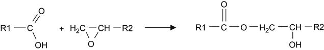 (11.6)
Such reactions can proceed in the epoxy resin with hardening agent under plasma treatment. Therefore, the plasma destruction products are active in curing reactions of epoxy resin, which means that the plasma places additional hardener into the epoxy resin. Due to additional hardener, the curing reaction proceeds deeper under plasma action than in the control sample.
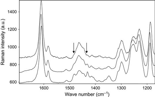
The completeness of polymerization reaction in epoxy resin with a TETA hardening agent was observed by Raman spectra. The Raman spectra of epoxy resin cured in air and plasma are presented in Figure 11.14. The lines at 1482 and 1430 cm−1 are observed in spectra of the initial resin. During reaction the intensity of these lines decreases, which corresponds to the reaction of polymerization. In spectra of the sample cured in plasma, the intensity of the 1482 and 1430 cm−1 lines is lower than in spectra of the sample cured in air.
In Figure 11.15, the normalized optical density of the carbonyl group line at 1730 cm−1 in FTIR transmission spectra is shown for liquid, cured epoxy resin, and for reactionable mixture. The absorbance of carbonyl groups in cured epoxy resin increases at initial plasma treatment and does not change during the next treatment phase. The oxidation takes place only in the thin surface layer of epoxy resin. Increasing treatment time in plasma does not lead to an increase in the carbonyl groups’ concentration in epoxy resin by more than a maximal amount on the surface layer. With an increase in treatment time, the carbonyl groups in the oxidized surface layer of the resin are destroyed by plasma particles during the etching process, as are other parts of macromolecules in the surface layer. Therefore, in solid epoxy resin, the formation of carbonyl groups and the etching process of the surface layer reach the dynamic equilibrium, and the concentration of the carbonyl groups becomes constant.
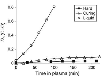
The increase in the carbonyl groups’ concentration at plasma treatment for liquid resin is significantly higher than for cured resin (Figure 11.15). The chemical structure of cured and liquid resin does not differ and it cannot be a reason for strong oxidation instability of liquid resin in plasma. During polymerization of epoxy resin, only the epoxy ring opens, and the structure of the macromolecule changes insignificantly. The product of polymerization becomes weaker with the action of oxygen. The significant difference between hard and liquid resin is their viscosity.
The difference in liquid and hard resin behavior in plasma treatment can be explained by a difference in the physical state of resins. The processes of mixing or flow can take place during plasma treatment, in liquid resin, but not in hard resin. Such processes can remove the oxidized layers from the treated surface of resin to the deep layer, and the oxygen-containing groups cannot be reached by plasma particles for destruction. At the same time, the new initial layers of resin appear on the surface and these new layers can be attacked by plasma particles, as previous ones were. During plasma treatment, the mixing process moves the new layers to the surface.
The intensive oxidation process of liquid epoxy resin in plasma is observed by the line at 3440 cm−1 of hydroxyl group vibrations (Figure 11.16). During curing reaction under atmospheric conditions, the intensity of the hydroxyl group line increases during reaction of polymerization corresponding to the appearance of hydroxyl groups as a product of the reaction. After curing, the intensity of the line does not change in the spectra of solid resin treated by plasma. However, in the spectra of liquid resin without hardening agent under plasma discharge, the intensity of the hydroxyl group line increases in correspondence to the increase of the carbonyl line intensity. If the epoxy resin is curing in plasma discharge, then the intensity of the hydroxyl group line increases more than at curing in air, as it is observed for the carbonyl group line.
The treated layer due to plasma action contains a number of active centers as free radicals, oxygen-containing groups, new double bonds, and others. During mixing, the treated layer is mixed with initial bulk layers of resin and the active centers can react with initial macromolecules of resin. During plasma treatment, the mixing process leads to a continuous moving of treated and untreated layers. As the result of treatment, the products of destruction and oxidation in bulk layers of liquid resin appear. It is observed as a strong increase in the intensity of carbonyl and hydroxyl groups’ lines in transmission spectra of epoxy resin under plasma treatment, which appear not only on the surface layer but also in the bulk layers.
The character of dependence of carbonyl line intensity changes with treatment time. The plasma etching of resin decreases the thickness of the sample to a low value when the mixing process cannot bring new initial layers of resin from bulk layers, and the treated oxidized layers come to the surface of the resin. In this case, the destruction of oxidized layers of resin becomes significant, and the equilibrium of oxidation and etching processes in the surface layer is observed as for solid resin. Therefore, the next increase in the oxidation of resin is impossible and the absorbance of carbonyl groups does not increase.
In the reactionable mixture of epoxy resin and hardening agent, the processes of etching, oxidation, and mixing take place dependent on viscosity of the mixture, which becomes more viscous with curing reaction time. The increase in carbonyl group concentration in the reactionable mixture is higher than in solid resin but lower than in liquid resin. The oxidation process has extreme dependence on treatment time. The influence of mixing on the oxidation process is observed as for liquid resin. The effect of oxidation is sufficiently lower than in liquid resin, due to the polymerization reaction and increase in mixture viscosity.
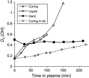
The morphology of the epoxy resin surface reflects the conditions of polymerization. AFM imaging does not show any defects on the surface of epoxy resin cured in a vacuum (Figure 11.17). After plasma treatment of hard epoxy resin, the surface becomes rough and defects, such as narrow peaks, appear. The same topology of the surface is observed in samples of solid polymers exposed in a free-space environment during space flight. Such topology corresponds to the etching process of hard material under plasma and ion beam.
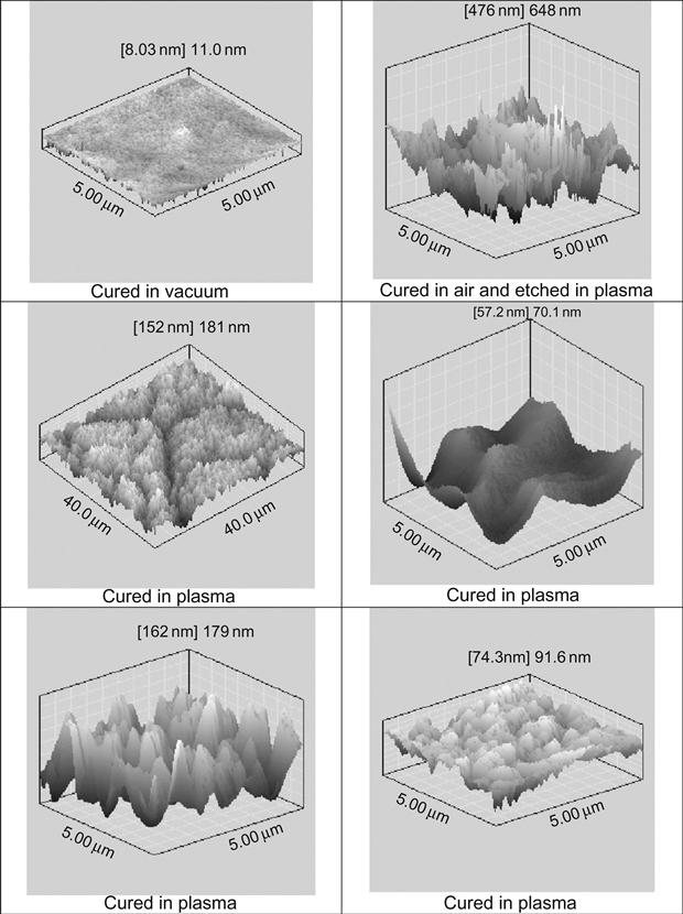
The surface topology of epoxy resin cured in plasma is more complicated and contains different regions with significantly different structures. For example, there are wrinkled structures, such as waves (Figure 11.18). The intensity and arrangement of wave structure are quite different. There is no clear distribution of wave structure by place, wave period, or intensity. The morphology of wave structure is disturbed by lines and cracks that are distributed on the treated surface without any order or clear direction. There are surface fields with smooth surfaces, like cured under atmospheric conditions. Some smooth fields contain weak narrow cracks. AFM imaging shows the detailed morphology of folded and smooth fields of surface after plasma treatment (Figure 11.17).
Such specific surface morphology can be interpreted as the observation of the frozen flow of liquid that flowed intensively before solidification. In the case of the TETA hardening agent, the surface of resin was cured in a plasma chamber and the structure of the surface was saved after treatment. In the case of the TEA hardening agent, the reactionable mixture was precured in plasma and postcured after plasma treatment in air. In all cases, the wrinkled structure of the surface was observed.
The surface topology of resin cured in plasma polymer reflects mixing processes caused by destruction processes in the polymer surface layer under ion and electron action. During treatment, the modified surface layer turns to bulk and the portion of unchanged polymer moves to the surface. Such a process slows down as viscosity increases, and stops when the polymer becomes hard. This picture corresponds also to FTIR and Raman results shown above.
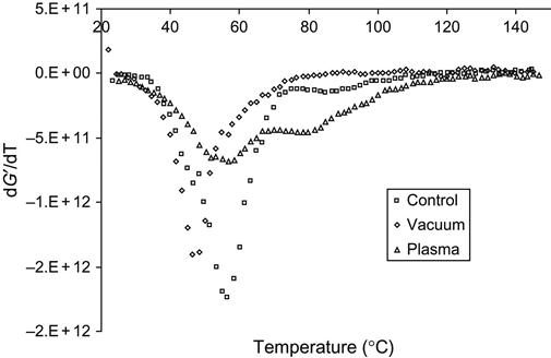
The deep structure transformations in the epoxy matrix during curing in vacuum, plasma, and ion beam cause changes of mechanical properties of the composite. After curing the composite based on epoxy matrix with a TEA hardening agent and glass fibers, the temperature behavior of modules was analyzed by dynamical mechanical analysis (DMA). The elastic modulus G′ of composite cured in air is higher than the module of composite cured after vacuum treatment, and lower than the module of composite cured in plasma. The temperature behavior of the modules for samples cured in vacuum, plasma, and air is different, as viewed on the G′ derivative curve (Figure 11.19). For the vacuum-treated sample, the phase transition (glass-transition temperature) is observed at a lower temperature than for the sample cured in air. For these samples, only one phase transition is observed. The composite cured in plasma has two phase transitions. The first peak of the G′ derivative is at the same temperature as the sample cured in air. But the peak becomes wider and lower with intensity. The second peak is observed at a higher temperature. Compared with spectral data, the second peak corresponds to the additional polymer network formed by free radicals that were generated by plasma discharge.