VHDL provides comprehensive facilities for expressing the behavior and structure of a design. VHDL also provides the attribute mechanism for annotating a model with additional information. In this chapter, we review the predefined attributes and show how to define new attributes. We also look at the group mechanism, which allows us to describe additional relationships between various items in a model.
Throughout this book we have seen predefined attributes that are used to retrieve information about types, objects and other items within a model. In this section we summarize the previously introduced attributes and fully describe the remaining predefined attributes.
VHDL-87
VHDL-87 provides two additional attributes beyond those described in the rest of this section. The attributes ‘behavior and ‘structure can be applied to the names of architecture bodies and that return a Boolean result. The ‘behavior attribute indicates whether the architecture body is a behavioral description. It returns true if the architecture body contains no component instantiation statements. The ‘structure attribute indicates whether the architecture body is a structural description. It returns true if the architecture body contains only component instantiations and passive processes. If both attributes are false, the architecture body is a mix of behavioral and structural modeling constructs.
The first group of predefined attributes gives information about the values in a scalar type. These were introduced in Chapter 2 and are summarized in Table 20.1.
Table 20.1. The predefined attributes giving information about values in a type
Attribute | Type of | Result type | Result |
|---|---|---|---|
| Any scalar type or subtype | Same as | Leftmost value in |
| ” | ” | Rightmost value in |
| ” | ” | Least value in |
| ” | ” | Greatest value in |
| ” |
|
|
| ” |
| A textual representation of the value xof type |
| ” | base type of | Value in |
| Any discrete or physi-cal type or subtype | universal integer | Position number of |
| ” | Base type of | Value at position |
| ” | ” | Value at position one greater than |
| ” | ” | Value at position one less than |
| ” | ” | Value at position one to the left of |
| ” | ” | Value at position one to the right of |
The second group of predefined attributes gives information about the index values of an array object or type. These were introduced in Chapter 4 and are summarized in Table 20.2. The prefix A in the table refers either to an array type or subtype whose index ranges are defined, to an array object, or to a slice of an array. If A is a variable of an access type pointing to an array object, the attribute refers to the array object, not the pointer value. Each of the attributes optionally takes an argument that selects one of the index dimensions of the array. The default is the first dimension. Note that if the prefix A is an alias for an array object, the attributes return information about the index values declared for the alias, not those declared for the original object.
Table 20.2. The predefined attributes giving information about the index range of an array
Attribute | Result |
|---|---|
| Leftmost value in index range of dimension |
| Rightmost value in index range of dimension |
| Least value in index range of dimension |
| Greatest value in index range of dimension |
| Index range of dimension |
A’reverse_range(n) | Index range of dimension nreversed in direction and bounds |
| Length of index range of dimension |
|
|
The third group of predefined attributes, summarized in Table 20.3, provides type information. The table describes the kind of prefix to which each attribute can be applied.
Table 20.3. The predefined attributes giving type information
Attribute | Prefix | Result |
|---|---|---|
| Any type or subtype | The base type of |
| Any object or alias of an object | The fully constrained subtype of |
| Any array type, subtype, or object | If |
The third group of predefined attributes gives information about signals or defines new implicit signals derived from explicitly declared signals. These attributes were introduced in Chapters 5 and 2 and are summarized in Table 20.4. The prefix S in the table refers to any statically named signal. Three of the attributes optionally take a non-negative argument t of type time. The default is 0 fs.
Table 20.4. The predefined attributes giving information about signals and values of signals
Attribute | Result type | Result |
|---|---|---|
| base type of | Implicit signal, with the same value as |
|
| Implicit signal, |
|
| Implicit signal, |
|
| Implicit signal, changes value in simulation cycles in which a transaction occurs on |
|
|
|
|
|
|
|
| Time since last event occurred on |
|
| Time since last transaction occurred on |
| base type of | Value of |
|
|
|
| base type of | Value contributed by driver for |
VHDL-87
The predefined attributes ‘driving and ‘driving_value are not provided in VHDL-87. Note also that the ‘last_value attribute for a composite signal returns the aggregate of last values for each of the scalar elements of the signal. This behavior is different from the VHDL-93 and VHDL-2002 behavior, in which the attribute returns the last value of the entire composite signal. Furthermore, the behavior of the ‘last_event and ‘last_active attributes differs from VHDL-93 and VHDL-2002. In VHDL-87, ‘last_event returns 0 ns if no event has yet occurred, and ‘last_active returns 0 ns if no transaction has yet occurred.
The remaining predefined attributes are applied to any declared item and return a string representation of the name of the item. These attributes are summarized in Table 20.5. The prefix X in the table refers to any declared item. If the item is an alias, the attribute returns the name of the alias itself, not the aliased item.
Table 20.5. The predefined attributes that provide names of declared items
Attribute | Result |
|---|---|
| A string representing the identifier, character or operator symbol defined in the declaration of the item |
| A string describing the path through the elaborated design hierarchy, from the top-level entity or package to the item |
| A string similar to that produced by |
The ‘simple_name attribute returns a string representation of the name of an item. For example, if a package utility_definitions in a library utilities declares a constant named word_size, the attribute
utilities.utility_definitions.word_size'simple_name
returns the string “word_size”. We might ask why VHDL provides this attribute, since we need to write the simple name of the item in order to apply the attribute. It would be simpler to write the string literal directly. If nothing else, we can use the attribute to gain consistency of style in reporting item names in messages, since the ‘simple_name attribute always returns a lowercase version of the name.
The ‘path_name and ‘instance_name attributes both return string representations of the path through the design hierarchy to an item. They are especially useful in assertion or report statements to pinpoint exactly which instance of a library unit is the source of a message. VHDL only requires that the message reported to the user by these statements indicate the name of the library unit (entity, architecture body or package) containing the statement. We can use the ‘path_name or ‘instance_name attribute to determine which particular instance of a process in the design hierarchy is the source of a message.
Example 20.1. Using name attributes in assertion messages
Suppose we have a design that includes numerous instances of a flipflop component bound to an entity flipflop and using an architecture behavior. Within this architecture we wish to include timing checks and report an error message if the constraints are violated. An outline of the architecture body incorporating these checks is
   architecture behavior of flipflop is
   begin
    timing_check : process (clk) is
    begin
      if clk = '1' then
        assert d'last_event >= Tsetup
          report "set up violation detected in "
                 & timing_check'path_name
          severity error;
      end if;
    end process timing_check;
    ...  -- functionality
   end architecture behavior;
When a flipflop instance in the design detects a timing violation, it will issue an assertion violation message indicating that the problem arose in the architecture behavior of flipflop. We use the ‘path_name attribute in the message string to identify which component instance bound to the flipflop entity is the one responsible for issuing the message.
The format of the string produced by the ‘path_name and ‘instance_name attributes for a library, a design-unit package, or an item declared in a design-unit package is described by the EBNF rule
   package_based_path  ⇐
      : library_logical_name :
           {(  subprogram_designator signature
               | variable_identifier
               | package_identifier  ) : }
           [ identifier | character_literal  | operator_symbol ]
The colon characters serve as punctuation, separating elements within the path string. If the item to which the attribute is applied is a library, the path string includes only the library name. If the item is a design-unit package, the path string includes the library name and the package name. If the item is declared in a package, the path string includes the library name, the package name and the name of the item. If the item is nested within a subprogram, shared variable, or local package in the design-unit package, the string also includes the names of the containing subprogram, shared variable, or local package. The signature of each subprogram is also included to distinguish between possibly overloaded versions of the subprogram name. Recall that the syntax rule for a subprogram signature is
signature ⇐ [ [ type_mark { , ... } ] [ return type_mark ] ]If the item is further nested, the names of all the enclosing subprograms, shared variables, or local packages are included in order from outermost to innermost.
Note that, for subprograms that overload operators, the name included in the path string is the operator symbol surrounded by quotation marks. For example, an overloaded abs operator declared in a package pkg in a library lib would have the path string:
:lib:pkg:"abs":
Example 20.2. Name attributes for items in a package
Suppose we have a package mem_pkg stored in the library project. The package declaration is
   package mem_pkg is
    subtype word is bit_vector(0 to 31);
    type word_array is array (natural range <>) of word;
    procedure load_array ( words : out word_array;
                           file_name : string );
   end package mem_pkg;
The ‘path_name attribute applied to these items gives the following results:
   mem_pkg'path_name = ":project:mem_pkg:"
   word'path_name = ":project:mem_pkg:word"
   word_array'path_name = ":project:mem_pkg:word_array"
   load_array'path_name = ":project:mem_pkg:load_array:"
The ‘instance_name attribute returns the same strings for these items. An outline of the package body is
   package body mem_pkg is
    procedure load_array ( words : out word_array;
                           file_name : string ) is
      -- words'path_name = ":project:mem_pkg:load_array:words"
      use std.textio.all;
      file load_file : text open read_mode is file_name;

      -- load_file'path_name
      --   = ":project:mem_pkg:load_array:load_file"
      procedure read_line is
      -- read_line'path_name
      --   = ":project:mem_pkg:load_array:read_line:"
        variable current_line : line;
        -- current_line'path_name
        --   = ":project:mem_pkg:load_array:read_line:current_line"
      begin
        ...
      end procedure read_line;
    begin  -- load_array
      ...
    end procedure load_array;
   end package body mem_pkg;
The comments indicate the values of the ‘path_name attribute applied to various names within the package body. Again, the ‘instance_name attribute returns the same strings as the ‘path_name attribute.
In the case of a shared variable, it is the name of the variable that is included in the path string, not the name of the protected type used to declare the variable. This allows us to distinguish between items declared in a protected type but occurring in different shared variables.
Example 20.3. Path name for items in shared variables
Suppose we have a package in library project_lib that declares a protected type, as follows:
   package counter_pkg is
    type counter is protected
      procedure increment;
      ...
    end protected counter;
   end package counter_pkg;
   package body counter_pkg is
    type counter is protected body
      constant limit : natural := 100;
      variable count : natural := 0;
      procedure increment is
      begin

        assert count < limit
          report "Counter overflow in " & increment'path_name;
        count := (count + 1) mod limit;
      end procedure increment;
      ...
    end protected body counter;
   end package body counter_pkg;
We now declare a package with two shared variables of the protected type:
   library project_lib;
   package system_counter_pkg is
    use project_lib.counter_pkg.all;
    shared variable test_counter, event_counter : counter;
   end package system_counter_pkg;
If, as a result of system operation, the assertion fails during execution of the method call test_counter.increment, the assertion message includes the path string
:work:system_counter_pkg:test_counter:increment:
This allows us to identify which instance of the protected type caused the assertion violation.
If an item is declared within an entity or architecture body, the ‘path_name and ‘instance_name attributes return different strings depending on the structure of the elaborated design and the location of the declared item within the design hierarchy. We first look at the string returned by the ‘path_name attribute, as it is the simpler of the two. The format of the string is described by the EBNF rules
   instance_based_path  ⇐
      : { path_instance_element : }
           [ simple_name | character_literal | operator_symbol ]
   path_instance_element ⇐
      entity_identifier
      | component_instantiation_label
      | block_label
      | generate_label  [ ( literal ) ]
      | [process_label ]
      |  subprogram_designator signature
      | [loop_label ]
      |  variable_identifier
      |  package_identifier
The string starts with the name of the topmost entity in the design and continues with the labels of any blocks (see Chapter 23), generate statements, processes, subprograms, and so on, between the top and the item. If the design hierarchy includes a component instance bound to an entity and architecture body containing the item, the attribute string includes the label of the component instantiation statement. If the item is contained within a for-generate statement, the string includes the value of the generate parameter for the particular iteration containing the item. The value is included in parentheses after the generate statement label. If the item is included in a process that has no label, the string includes an empty element in place of a process label. If the item is included in a subprogram, the string includes the signature of the subprogram to distinguish between possibly overloaded versions of the subprogram name. If the item is the loop parameter of a for loop, the string includes the label of the loop, or an empty element if the loop is unlabeled. If the item is declared in a protected type used as the type of a variable, the string includes the name of the variable (not the name of the protected type). If the item is included within a locally declared package, the string includes the package name.
The format of the string returned by the ‘instance_name attribute is described by the EBNF rules
   full_instance_based_path  ⇐
       : { full_path_instance_element :  }
            [ simple_name | character_literal | operator_symbol ]

   full_path_instance_element  ⇐
       entity_identifier ( architecture_identifier )
       |component_instantiation_ label
                    @ entity_identifier ( architecture_identifier )
       |block_label
       |generate_label [ ( literal ) ]
       |[process_label ]
       |subprogram_designator signature
       |[loop_label ]
       |variable_ identifier
       |package_ identifier
It is the same as that returned by ‘path_name, except that the names of the entity and architecture bound to a component instance are included after the label of the component instantiation statement. Furthermore, the architecture name for the top-level design entity is also included.
Example 20.4. Name attributes in a design hierarchy
We illustrate the results returned by the ‘path_name and ‘instance_name attributes by looking at a sample design hierarchy. The top level of the hierarchy is formed by the entity top and its corresponding architecture top_arch, declared as follows:
   entity top is
   end entity top;
   --------------------------------------------------
   architecture top_arch of top is

    signal top_sig : ...;                  -- 1
   begin
    stimulus : process is
      variable var : ...;                  -- 2
    begin
      ...
    end process stimulus;
    rep_gen : for index in 0 to 7 generate
    begin
      end_gen : if index = 7 generate
        signal end_sig : ...;              -- 3
      begin
        ...
      end generate end_gen;
      other_gen : if index /= 7 generate
        signal other_sig : ...;            -- 4
      begin
        other_comp : entity work.bottom(bottom_arch)
          port map ( ... );
      end generate other_gen;
    end generate rep_gen;
   end architecture top_arch;
The numbered comments in this model mark points at which various declared items are visible. The values of the ‘path_name and ‘instance_name attributes of these items at the marked points are shown in Table 20.6. At point 4, the string returned varies between repetitions created by the generator. Where the table shows index in the attribute value, the value of the generate parameter for that repetition is substituted. For example, in the repetition with the generate parameter set to 4, the result of other_sig‘path_name is “:top:rep_gen(4):other_gen:other_sig”.
The entity declaration and architecture body for the bottom level of the design hierarchy, instantiated in the preceding architecture body, are
   entity bottom is
    port ( ... );
   end entity bottom;
   --------------------------------------------------
   architecture bottom_arch of bottom is
    signal bot_sig : ...;             -- 5
    procedure proc ( ... ) is
      variable v : ...;               -- 6
    begin
      ...
    end procedure proc;
   begin
    delays : block is
      constant d : integer := 1;      -- 7
    begin
      ...
    end block delays;
    func : block is
    begin
      process is
        variable v : ...;             -- 8
      begin
        ...
      end process;
    end block func;
   end architecture bottom_arch;
The architecture includes block statements, which we describe in detail in Chapter 23. Nonetheless, we include them here to illustrate the form of path strings involving them. The values of the ‘path_name and ‘instance_name attributes of items within this architecture at the marked points are shown in Table 20.7. The values shown are for the instance of the architecture corresponding to the component instantiation statement in the repetition of rep_gen with index set to 4. Point 8 is within a process that has no label, so the strings returned for the item v include an empty element (two consecutive colon characters) where the process label would otherwise be.
Table 20.6. The results of applying the path and instance name attributes at the top level
Point | Item | Item ‘ |
|---|---|---|
1 |
| :top: :top(top_arch): |
1 |
| :top:top_sig :top(top_arch):top_sig |
2 |
| :top:stimulus: :top(top_arch):stimulus: |
2 |
| :top:stimulus:var :top(top_arch):stimulus:var |
3 |
|
|
4 |
|
|
Table 20.7. The results of applying the path and instance name attributes at the bottom level
Item | Item | |
|---|---|---|
5 |
|
|
6 |
|
|
7 |
|
|
8 |
|
|
VHDL-93 and -2002
In these versions, the path element for a subprogram was officially an identifier, so an overloaded operator symbol could not be represented. This was an error of specification in the VHDL standard, so most implementations would have assumed some representation for the operator symbol. Also, in these versions, there was no provision for names of variables (shared or otherwise) of protected types or for loop labels in path strings. Finally, since these versions do not allow locally declared packages, there is no provision for package names other than as design-unit packages in package-based paths.
VHDL-93
The signature for a subprogram is not included in the ‘path_name and ‘instance_name attributes in VHDL-93. Furthermore, the specification of these attributes in the VHDL-93 Language Reference Manual is ambiguous and contains contradictory examples. As a consequence, the results returned by the attributes is somewhat implementation dependent.
The predefined attributes provide information about types, objects or other items in a VHDL model. VHDL also provides us with a way of adding additional information of our own choosing to items in our models, namely, through user-defined attributes. We can use them to add physical design information such as standard cell allocation and placement, layout constraints such as maximum wire delay and inter-wire skew or information for synthesis such as encodings for enumeration types and hints about resource allocation. In general, information of a non-structural and non-behavioral nature can be added using attributes and processed using software tools operating on the design database.
The first step in defining an attribute is to declare the name and type of an attribute, using an attribute declaration. The syntax rule describing this is
attribute_declaration ⇐ attribute identifier : type_mark ;An attribute declaration simply defines the identifier as representing a user-defined attribute that can take on values from the specified type. The type can be any VHDL type except an access, file or protected type or a composite type with a subelement that is an access, file or protected type. Some examples of attribute declarations are
   attribute cell_name : string;
   attribute pin_number : positive;
   attribute max_wire_delay : delay_length;
   attribute encoding : bit_vector;
The attribute type need not be a simple scalar. For example, we might define an attribute to represent cell placement as follows:
   type length is range 0 to integer'high
    units nm;
      um = 1000 nm;
      mm = 1000 um;
      mil = 25400 nm;
    end units length;
   type coordinate is record
      x, y : length;
    end record coordinate;
   attribute cell_position : coordinate;
Once we have defined an attribute name and type, we then use it to decorate items within a design. We write attribute specifications, nominating items that take on the attribute with particular values. The syntax rules for an attribute specification are
   attribute_specification  ⇐
      attribute identifier of entity_name_list : entity_class is expression ;
   entity_name_list  ⇐
      ( ( identifier | character_literal | operator_symbol ) [ signature ] ) { , ...}
       | others
       | all
   entity_class ⇐
      |entity            |architecture       |configuration       |package
       |procedure        |function           |type                |subtype
       |constant         |signal             |variable            |file
       |component        |label              |literal             |units
       |group            |property           |sequence
The first identifier in an attribute specification is the name of a previously declared attribute. The items to be decorated with this attribute are listed in the entity name list. Note that we use the term “entity” here to refer to any item in the design, not to be confused with an entity interface defined in an entity declaration. We adopt this terminology to remain consistent with the VHDL Language Reference Manual, since you may need to refer to it occasionally. However, we use the term as little as possible, preferring instead to refer to “items” in the design, to avoid confusion. The items to be decorated with the attribute are those named items of the particular kind specified by the “entity” class. The list of classes shown covers every kind of item we can name in a VHDL description, so we can decorate any part of a design with an attribute. Finally, the actual value for the attribute of the decorated items is the result of the expression included in the attribute specification. Here are some examples of attribute specifications using the attributes defined earlier:
   attribute cell_name of std_cell : architecture is "DFF_SR_QQNN";
   attribute pin_number of enable : signal is 14;
   attribute max_wire_delay of clk : signal is 50 ps;
   attribute encoding of idle_state : literal is b"0000";
   attribute cell_position of the_fpu : label is ( 540 um, 1200 um );
In the case of an attribute declared to be of a composite type, we can write the attribute value in the form of an aggregate or string or bit-string literal. The type can be an unconstrained or partially constrained subtype, in which any index ranges not defined by the subtype are determined from the attribute value. For example, if we declare an attribute of a composite type:
   type string_vector is array (positive range <>) of string;
   attribute key_vector : string_vector;
we can decorate an item with the attribute as follows:
   attribute key_vector of e : entity is
    ("66A6D 7DF3A 88CE1 8DEEB", "012BD 2BEE9 98634 93FE1");
Since the subtype for the attribute specifies index ranges in neither the top-level nor the element position, the corresponding index ranges of the aggregate are used to determine the index ranges for the attribute value, giving the ranges 1 to 2 for the top level and 1 to 23 for each element.
We now look at how attribute values may be specified for each of the classes of items shown in the syntax rule. For most classes of items, an attribute specification must appear in the same group of declarations as the declaration for the item being decorated. However, the first three classes shown in the syntax rule are design units that are placed in a design library as library units when analyzed. They are not declared within any enclosing declarative part. Instead, we can consider them as being declared in the context of the design library. The same also applies to packages that are declared as design units, as opposed to being declared locally within a design unit. However, this presents a problem if we wish to decorate an item of one of these classes with an attribute. For entities, architectures, configurations and packages, we solve this problem by placing the attribute specification in the declarative part of the design unit itself. For example, we decorate an architecture std_cell with the cell_name attribute as follows:
   architecture std_cell of flipflop is
    attribute cell_name of std_cell : architecture is "DFF_SR_QQNN";
    ...  -- other declarations
   begin
    ...
   end architecture std_cell;
In the case of packages, this rule applies whether a package is declared as a design unit or locally. The attribute specification must be included in the package declaration, not the package body. For example, we can decorate a package model_utilities with the optimize attribute as follows:
   package model_utilities is
    attribute optimize : string;
    attribute optimize of model_utilities : package is "level_4";
    ...
   end package model_utilities;
When we decorate subprograms we may need to distinguish between several overloaded versions. The syntax rule on page 617 shows that we can include a signature to identify one version uniquely by specifying the types of its parameters and return value. Signatures were introduced in Chapter 11.
Example 20.5. Decorating a subprogram
If we have two overloaded versions of the procedure add_with_overflow declared in a process as shown below, we can decorate them using signatures in the attribute specification.
    procedure add_with_overflow ( a, b : in integer;
                                  sum : out integer;
                                  overflow : out boolean ) is ...
    procedure add_with_overflow ( a, b : in bit_vector;
                                  sum : out bit_vector;
                                  overflow : out boolean ) is ...
    attribute built_in : string;
    attribute built_in of
      add_with_overflow [ integer, integer,
                          integer, boolean ] : procedure is
   "int_add_overflow";
    attribute built_in of
      add_with_overflow [ bit_vector, bit_vector,
                          bit_vector, boolean ] : procedure is
   "bit_vector_add_overflow";
   begin
    ...
   end process;
The syntax rule also shows that we can identify an overloaded operator by writing the operator symbol as the function name. For example, if we declare a function to concatenate two lists of stimulus vectors:
function "&" ( a, b : stimulus_list ) return stimulus_list;
we can decorate it with an attribute as follows:
   attribute debug : string;
   attribute debug of "&" [ stimulus_list, stimulus_list
                           return stimulus_list ] : function is
                      "source_statement_step";
The syntax rules for attribute specifications show the signature to be optional, and indeed, we can omit it when decorating subprograms. In this case, the attribute specification applies to all subprograms with the given name and class declared in the same declarative part as the attribute specification. For example, if we declare the following overloaded subprograms:
   procedure add ( a, b : in integer; s : out integer );
   procedure add ( a, b : in real; s : out real );
   function add ( a, b : integer ) return integer;
   function add ( a, b : real ) return real;
and write and attribute declaration and specifications:
   attribute built_in : boolean;
   atribute built_in of add : procedure is true;
   attribute built_in of add : function is false;
the two procedures are decorated with the attribute value true, and the two functions are decorated with the attribute value false.
We can decorate a type, subtype or data object (a constant, variable, signal or file) by including an attribute specification after the declaration of the item. The attribute specification must appear within the same declarative part as the declaration of the item. For example, if we declare a resolved subtype resolved_mvl:
   type mvl is ('X', '0', '1', 'Z'),
   type mvl_vector is array ( integer range <>) of mvl;
   function resolve_mvl ( drivers : mvl_vector ) return mvl;
   subtype resolved_mvl is resolve_mvl mvl;
we can decorate it as follows:
   type builtin_types is (builtin_bit, builtin_mvl, builtin_integer);
   attribute builtin : builtin_types;
   attribute builtin of resolved_mvl : subtype is builtin_mvl;
Generics and ports in the interface of an entity can be decorated with attributes. Generic constants are of constant class, generic types are of type class, generic subprograms are of procedure or function class, generic packages are of package class, and ports are of signal class. The interface list is considered to be in the declarative part of the entity. Hence, we write attribute specifications for generics and ports in the declarative part of the entity.
Example 20.6. Decorating generics and ports of an entity
Suppose the package physical_attributes declared the following attributes:
   attribute layout_ignore : boolean;
   attribute pin_number : positive;
We can declare an entity with decorated generic constants and ports as follows:
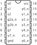
   library ieee;  use ieee.std_logic_1164.all;
   use work.physical_attributes.all;

   entity 74x138 is
    generic ( Tpd : time );
    port ( en1, en2a_n, en2b_n : in std_ulogic;
           s0, s1, s2 : in std_ulogic;
           y0, y1, y2, y3, y4, y5, y6, y7 : out std_ulogic );
    attribute layout_ignore of Tpd : constant is true;
    attribute pin_number of s0 : signal is 1;
    attribute pin_number of s1 : signal is 2;
    attribute pin_number of s2 : signal is 3;
    attribute pin_number of en2a_n : signal is 4;
    ...
   end entity 74x138;
Subprogram parameters can also be decorated with attributes. The class is specified or implied in the interface list of the subprogram. We write the attribute specifications for subprogram parameters in the declarative part of the subprogram. Similarly, for uninstantiated subprograms, we can decorate the generics by writing attribute specifications in the declarative part. For uninstantiated packages, we can decorate the generics by writing attribute specification in the package declaration (not the package body). In both cases, the classes of generics are as described above for generics of entities.
Example 20.7. Decorating parameters of a subprogram
The following procedure has three parameters of different classes. Attribute specifications for the parameters are included in the declarative part of the procedure.
   procedure mem_read ( address : in natural;
                       result : out byte_vector;
                       signal memory_bus : inout ram_bus ) is
    attribute trace of address : constant is "integer/hex";
    attribute trace of result : variable is "byte/multiple/hex";
    attribute trace of memory_bus : signal is
                        "custom/command=rambus.cmd";
    ...
   begin
    ...
   end procedure mem_read;
We can decorate a component in a model by including an attribute specification along with the component declaration. An important point to realize is that the attribute decorates the template defined by the component declaration. It does not decorate component instances that use that template.
Example 20.8. Decorating a component declaration
The package below includes a component declaration for an and gate. The package imports two attributes, graphic_symbol and graphic_style, from a second package graphics_pkg in the library graphics and decorates the component template with each of these attributes.
   library ieee;  use ieee.std_logic_1164.all;
   library graphics;
   package gate_components is
    use graphics.graphics_pkg.graphic_symbol,
        graphics.graphics_pkg.graphic_style;
    component and2 is
      generic ( prop_delay : delay_length );
      port ( a, b : in std_ulogic;  y : out std_ulogic );
    end component and2;
    attribute graphic_symbol of and2 : component is "and2";
    attribute graphic_style of and2 : component is
                                "color:default, weight:bold";
    ...
   end package gate_components;
If we wish to decorate a component instance or any other concurrent statement with an attribute, we do so by decorating the label of the statement. The label is implicitly declared in the declarative part of the architecture or block containing the concurrent statement. Hence, we place the attribute specification in that declarative part.
Example 20.9. Decorating a component instance
We might decorate a component instance in an architecture body with an attribute describing cell placement as follows:
   architecture cell_based of CPU is
    component fpu is
      port ( ... );
    end component;
    use work.cell_attributes.all;
    attribute cell_position of the_fpu : label is
                               ( 540 um, 1200 um );
    ...

   begin
    the_fpu : component fpu
      port map ( ... );
    ...
   end architecture cell_based;
We can decorate sequential statements within a process or a subprogram in a similar way. The syntax rules for sequential statements show that each kind of sequential statement may be labeled. We decorate a sequential statement by specifying an attribute for the label. We place the attribute specification in the declarative part of the process or subprogram containing the sequential statement.
Example 20.10. Decorating a sequential statement
If we wish to decorate a loop statement in a process with the attribute synthesis_hint, we do so as follows:
   controller : process is
    attribute synthesis_hint of control_loop : label is
                                "implementation:FSM(clk)";
    ...
   begin
    ...  -- initialization
    control_loop : loop
      wait until clk = '1';
      ...
    end loop;
   end process controller;
When we introduced aliases and signatures in Chapter 11, we mentioned that enumeration literals can be thought of as functions with no parameters that return values of their enumeration types. We can take the same approach when decorating enumeration literals with attributes, in order to distinguish between literals of the same name from different enumeration types.
Example 20.11. Decorating an enumeration literal
If we have two enumeration types declared as
   type controller_state is (idle, active, fail_safe);
   type load_level is (idle, busy, overloaded);
we can decorate the literals of type controller_state as follows:
   attribute encoding of
    idle [ return controller_state ] : literal is b"00";
   attribute encoding of
    active [ return controller_state ] : literal is b"01";
   attribute encoding of
    fail_safe [ return controller_state ] : literal is b"10";
The signature associated with the literal idle indicates that it is of type controller_state, not load_level. As with attribute specifications for subprograms, if a signature is not included for a literal, all literals of the given name declared in the same declarative part as the attribute specification are decorated with the attribute.
When we declare a physical type we introduce a primary unit name and possibly a number of secondary unit names. Each of the unit names is a declared item and so may be decorated with attributes.
Example 20.12. Decorating a physical unit
The package below defines a physical type voltage. It also declares an attribute, resolution, and decorates each of the units of voltage with this attribute.
   package voltage_defs is
    type voltage is range -2e9 to +2e9
      units
        nV;
        uV = 1000 nV;
        mV = 1000 uV;
        V = 1000 mV;
      end units voltage;
    attribute resolution : real;
    attribute resolution of nV : units is 1.0;
    attribute resolution of uV : units is 0.01;
    attribute resolution of mV : units is 0.01;
    attribute resolution of V : units is 0.001;
   end package voltage_defs;
If we embed PSL code in a VHDL model, we can decorate declared properties and sequences. For example:
   property SingleCycleRequest is
    always req -> next not req;

   sequence ReadCycle is
    { ba; {bb[*]} && {ar[->]; dr[->]}; not bb };
   attribute enable_heuristics of
              SingleCycleRequest : propery is true;
   attribute enable_heuristics of ReadCycle : sequence is true;
The one remaining class of items that can be decorated with attributes is groups. We introduce groups in the next section and show examples of decorated groups.
If we return to the syntax rules for attribute specifications, shown on page 617, we see that we can write the keyword others in place of the list of names of items to be decorated. If we do so, the attribute specification applies to all items of the given class in the declarative part that are not otherwise decorated with the attribute. Such an attribute specification must be the last one in the declarative part that refers to the given attribute name and item class.
Example 20.13. Decorating items not previously decorated
In the following architecture body, signals are decorated with attributes specifying the maximum allowable delays due to the physical layout. The two signals recovered_clk1 and recovered_clk2 are explicitly decorated with the attribute value 100 ps. The remaining signals are decorated with the value 200 ps.
   library ieee;  use ieee.std_logic_1164.all;
   use work.timing_attributes.all;
   architecture structural of sequencer is
    signal recovered_clk1, recovered_clk2 : std_ulogic;
    signal test_enable : std_ulogic;
    signal test_data : std_ulogic_vector(0 to 15);
    attribute max_wire_delay of
      recovered_clk1, recovered_clk2 : signal is 100 ps;
    attribute max_wire_delay of others : signal is 200 ps;
    ...
   begin
    ...
   end architecture structural;
The syntax rules also show that we can use the keyword all in place of a list of item names. In this case, all items of the given class defined in the declarative part containing the attribute specification are decorated. Such an attribute specification must be the only one in the declarative part to refer to the given attribute name and item class.
Although we can only decorate an item with one value for a given attribute name, we can decorate it with several different attributes. We simply write one attribute specification for each of the attributes decorating the item. For example, a component instance labeled mult might be decorated with several attributes as follows:
   attribute cell_allocation of
    mult : label is "wallace_tree_multiplier";
   attribute cell_position of
    mult : label is ( 1200 um, 4500 um );
   attribute cell_orientation of
    mult : label is down;
If an item in a design is decorated with a user-defined attribute, we can refer to the attribute value using the same notation that we use for predefined attributes. The syntax rule for an attribute name referring to a user-defined attribute is
attribute_name ⇐ name [ signature ] ' identifier
If the name of the item is unambiguous, we can simply write an apostrophe and the attribute name after the item name. For example:
   std_cell'cell_name
   enable'pin_number
   clk'max_wire_delay
   v4 := idle_state'encoding
   the_fpu'cell_position
In the case of attributes decorating subprograms or enumeration literals, it may be necessary to use a signature to distinguish between a number of alternative names. For example, we might refer to attribute values of different versions of an increment function as
   increment [ bit_vector return bit_vector ] 'built_in
   increment [ std_ulogic_vector return std_ulogic_vector ] 'built_in
Similarly, we might refer to attribute values of enumeration literals as
   high [ return speed_range ] 'representation
   high [ return coolant_level ] 'representation
While it is legal VHDL to refer to attribute values such as these in expressions, it is not good design practice to use attribute values to affect the structure or behavior of the model. It is better to describe structure and behavior using the language facilities intended for that purpose and use attributes to annotate the design with other kinds of information for use by other software tools. For this reason, we do not further discuss the use of attribute values in models. Software tools that use attributes should include documentation describing the required attribute types and their usage.
In Chapter 11, we introduced aliases as a way of defining alternate names for items in a design. In most cases, referring to an item using an alias is exactly the same as referring to it using its original name. The same interpretation holds when decorating items with attributes. When we use an alias of an item in an attribute specification, it is the original object denoted by the alias that is decorated, not the alias. This is the interpretation we saw for the predefined attributes discussed in the previous section. The exceptions are the predefined attributes that return the path name of an item and those that return information about the index ranges of arrays. One restriction on decorating data objects using aliases is that we may only do so using aliases that denote whole objects, not elements or slices of records or arrays. This restriction corresponds to the restriction that an attribute must decorate a whole object. The syntax rule for an attribute specification does not provide for naming parts of objects, since we can only write a simple identifier as an object name.
One final point to mention about user-defined attributes relates to component instantiation statements and to subprogram calls. In a component instantiation statement, actual signals are associated with formal ports of an entity. If the actual signal is decorated with an attribute, the attribute information is only visible in the context of the actual signal, namely, in the architecture body in which the signal is declared. It is not carried through to the instantiated entity. For example, if we have a signal s decorated with an attribute attr, we might use it as an actual signal in a component instantiation statement:
   c1 : entity work.e(arch)
    port map ( p => s );
Within the architecture body arch, we cannot refer the attribute of the signal using the notation p’attr. This notation instead refers to the attribute attr of the port p, which can only be defined in the entity declaration.
In a subprogram call an actual parameter (such as a constant, variable, signal or file) is associated with a formal parameter of the subprogram. If the actual parameter is decorated with an attribute, that attribute information is likewise not carried through to the subprogram. The decoration is purely local to the region in which the actual object is declared.
VHDL-87, -93, and -2002
Since these versions of VHDL do not allow PSL code to be embedded within VHDL models, we cannot use the word property or sequence attribute specifications for the class of an item to be decorated.
VHDL-87
The syntax rules for attribute specifications in VHDL-87 do not allow us to name a character literal as an item to be decorated. Nor may we specify the entity class literal, units, group or file. Furthermore, we may not include a signature after an item name. Hence there is no way to distinguish between overloaded subprograms or enumeration literals; all items of the given name are decorated.
The user-defined attribute facility discussed in the previous section allows us to annotate individual items in a design with non-structural and non-behavioral information. However, much of the additional information we may need to include can best be expressed as relationships between collections of items, rather than pertaining to individual items. For this reason VHDL provides a grouping mechanism to identify a collection of items over which some relationship holds. The information about the relationship is expressed as an attribute of the group. In this section we see how to define kinds of groups, to identify particular groups of related items and to specify attributes for particular groups.
The first stage in grouping items is to define a template for the classes of items that can be included in the group. We do this with a group template declaration, for which the syntax rule is
   group_template_declaration  ⇐
      group identifier is ( (entity_class [ <> ] ) {, ...) ;
A group template declaration lists one or more classes of items, in order, that may constitute a group. Note that the syntax rule uses the term “entity” here in the same way as the rules for attribute specifications, namely, to refer to any kind of item in a design. We discuss the meaning of the “<>” notation shortly. An example of a group template declaration is
group signal_pair is (signal, signal);
This defines a template for groups consisting of two signals. We can use this template to define a number of groups using group declarations. The syntax rule for a group declaration is
   group_declaration  ⇐
      group identifier : group_template_name
          ( ( name | character_literal ) { , ... } ) ;
A group declaration names a template to use for the group and lists the items that are to be members of the group. Each item in the list must be of the class specified in the corresponding position in the template. For example, if we have two clock signals in a design, clk_phase1 and clk_phase2, we can group them together using the signal_pair template defined above by writing
group clock_pair : signal_pair ( clk_phase1, clk_phase2 );As we mentioned earlier, the main use of groups is as a mechanism for defining relationships between items by decorating a group of items with an attribute. We decorate a group by naming it in an attribute specification, identifying it as an item of class group. For example, if we have an attribute declared as
attribute max_skew : time;we can decorate the clock_pair group with this attribute as follows:
attribute max_skew of clock_pair : group is 200 ps;
The decoration can be interpreted as an annotation to the design, indicating to a layout tool that the maximum permissible skew between the two signals in the group is 200 ps.
The syntax rule for a group template shows that we may write the box symbol (“<>”) after an item class. In fact, we may only include such a class specification once in any template, and it must be in the last position in the list of item classes. It indicates that a group based on that template may have an indefinite number of elements of the given class (including none).
Example 20.14. Groups for physical packaging
We can define a group template for a group representing component instances to be allocated to the same physical package. The members of such a group are the labels of the component instances. The group template declaration is
group component_instances is ( label <> );
We can use the template to create groups of instances:
   group U1 : component_instances ( nand1, nand2, nand3 );
   group U2 : component_instances ( inv1, inv2 );
We can specify what kind of integrated circuit should be used for each group by defining an attribute and using it to decorate the group:
   attribute IC_allocation : string;
   attribute IC_allocation of U1 : group is "74LS00";
   attribute IC_allocation of U2 : group is "74LS04";
An individual item in a design can belong to more than one group. We simply include its name in the declaration of each group of which it is a member.
Example 20.15. Groups for port-to-port timing constraints
We can use groups of signals as the basis for annotating a design entity with port-to-port timing constraints. Suppose we declare a group template port_pair and an attribute max_prop_delay in a package constraints:
   group port_pair is ( signal, signal );
   attribute max_prop_delay : time;
We can then use the template to group pairs of ports of an entity and annotate them with constraint attributes, as follows:
   library ieee;  use ieee.std_logic_1164.all;
   use work.constraints.port_pair, work.constraints.max_prop_delay;
   entity clock_buffer is
    port ( clock_in : in std_ulogic;
           clock_out1, clock_out2, clock_out3 : out std_ulogic );
    group clock_to_out1 : port_pair ( clock_in, clock_out1 );
    group clock_to_out2 : port_pair ( clock_in, clock_out2 );
    group clock_to_out3 : port_pair ( clock_in, clock_out3 );
    attribute max_prop_delay of clock_to_out1 : group is 2 ns;
    attribute max_prop_delay of clock_to_out2 : group is 2 ns;
    attribute max_prop_delay of clock_to_out3 : group is 2 ns;
   end entity clock_buffer;
In this entity declaration, the item clock_in is a member of each of the three groups clock_to_out1, clock_to_out2 and clock_to_out3.
[
| |
[ dut : entity work.counter(registered) port map ( ... ); The test bench entity name is
What are the values of the | |
[ type capacitance is range 0 to integer'high units pF; end units capacitance; write an attribute declaration that represents a capacitive load and an attribute specification that decorates a signal | |
[ | |
[ attribute optimization : string;decorate the following procedure with the attribute value “inline”. Assume that another overloaded version of the procedure, which must not be decorated, is visible. procedure test_empty ( variable list : in list_ptr; is_empty : out boolean ) is ... | |
[ step_1 : a := b * c + k; step_2 : n := a + 4 * j; Then, write an attribute specification that decorates the group with the attribute | |
7. | [ |
8. | [ |
9. | [ |
10. | [ Since the “and” function is commutative and associative, a layout tool should be able to permute the connections within each of the groups a1, a2, a3 and b1, b2, b3 without affecting the function performed by the circuit. Include in the entity interface of the and-or-invert gate a group template declaration and group declarations that encompass ports among which connections may be permuted. |