In the preceding chapters we introduced most of the facilities provided by VHDL and showed how they may be used to model a variety of hardware systems at various levels of detail. However, there remain a few VHDL facilities that we have not yet discussed. In this chapter, we tie off these loose ends.
In this section we look at a number of closely related topics. First, we discuss another kind of resolved signal called a guarded signal. We see how we can disconnect drivers from such signals. Next, we introduce the idea of blocks in a VHDL design. We show how blocks and guarded signals work together with guards and guard expressions to cause automatic disconnection of drivers. Finally, we discuss blocks as a mechanism for describing a hierarchical structure within an architecture. While these aspects of VHDL may be useful in some designs, they are not widely used. Hence, we have deferred consideration of the features to this chapter.
In Chapter 8 we saw how we can use resolved signals that include values such as ‘Z’ for modeling high-impedance outputs. However, if we are modeling at a higher level of abstraction, we may wish to use a more abstract type such as an integer type or a simple bit type to represent signals. In such cases, it is not appropriate to include the high-impedance state as a value, so VHDL provides us with an alternative approach, using guarded signals. These are resolved signals for which we can disconnect the drivers; that is, we can cause the drivers to stop contributing values to the resolved signal. We see why these signals are called “guarded” later in this section. First, let us look at the complete syntax rule for a signal declaration, which includes a means of declaring a signal to be guarded.
   signal_declaration  ⇐
       signal identifier  {, ...} : subtype_indication  [register | bus]
                                 [:= expression];
The difference between this rule and the simplified rule we introduced earlier is the inclusion of the option to specify the signal kind as either a register signal or a bus signal. Note that a guarded signal must be a resolved signal. Hence, the subtype indication in the signal declaration must denote a resolved subtype. Some examples of declarations of guarded signals are
   signal interrupt_request : pulled_up bit bus;

   signal stored_state : resolve_state state_type register
            := init_state;
The difference between the two kinds of guarded signals lies in their behavior when all of their drivers are disconnected. A bus signal uses the resolution function to determine the signal value by passing it an empty array. The bus kind of guarded signal can be used to model a signal that is “pulled up” to some value dependent on the signal type when all drivers are disconnected. A register signal, on the other hand, keeps the resolved value that it had just before the last disconnection. The register kind of guarded signal can be used to model signals with dynamic storage, for example, signals in CMOS logic that store data as charge on transistor gates when all drivers are disconnected. Note that a signal may be neither a register nor a bus signal, in which case it is a regular (unguarded) signal, from which drivers may not be disconnected.
A process can disconnect a driver for a guarded signal by specifying a null transaction in a signal assignment statement. As a reminder, the syntax rule we used to introduce a signal assignment was
signal_assignment_statement  ⇐
     [label :] name <= [delay_mechanism] waveform;
The waveform is a sequence of transactions, that is, new values to be applied to the signal after given delays. A more complete syntax rule for waveforms includes null transactions:
waveform  ⇐
   (value_expression [after time_expression]
       |null [after time_expression]){, ...}
This rule shows that instead of specifying a value in a transaction, we can use the keyword null to indicate that the driver should be disconnected after the given delay. When this null transaction matures, the driver ceases to contribute values to the resolution function used to compute the signal’s value. Hence the size of the array of values passed as an argument to the resolution function is reduced by one for each driver that currently has a null transaction determining its contribution. When a driver subsequently performs a non-null transaction, it reconnects and contributes the value in the non-null transaction.
Example 23.1. Disconnection from a bus of type bit
Following is an outline of an architecture body for a computer system consisting of a CPU, a memory and a DMA controller.
   architecture top_level of computer_system is
    function resolve_bits ( bits : bit_vector ) return bit is
      variable result : bit := '0';
    begin
      for index in bits'range loop
        result := result or bits(index);
        exit when result;
      end loop;
      return result;
    end function resolve_bits;
    signal write_en : resolve_bits bit bus;
    ...
   begin
    CPU : process is
      ...
    begin
      write_en <= '0' after Tpd;
      ...
      loop
        wait until clock;
        if hold_req then
          write_en <= null after Tpd;
          wait on clock until clock and not hold_req;
          write_en <= '0' after Tpd;
        end if;
        ...
      end loop;
    end process CPU;
    ...
   end architecture top_level;
The architecture body includes a guarded signal of kind bus, write_en, representing a control connection to the memory. The resolution function performs the logical “or” operation of all of the contributing drivers and returns ‘0’ if there are no drivers connected. This result ensures that the memory remains inactive when neither the CPU nor the DMA controller is driving the write_en control signal.
When the process representing the CPU is initialized, it drives write_en with the value ‘0’. Subsequently, when the DMA controller requests access to the memory by asserting the hold_req signal, the CPU schedules a null transaction on write_en. This transaction removes the CPU’s driver from the set of drivers contributing to the resolved value of write_en. Later, when the DMA controller negates hold_req, the CPU reconnects its driver to write_en by scheduling a transaction with the value ‘0’.
Example 23.2. Disconnection from a bus of type bit_vector
An outline of a register-transfer-level model of a processor, in which datapath elements are modeled by processes, is
   architecture rtl of processor is
    subtype word is bit_vector(0 to 31);
    type word_vector is array (natural range <>) of word;
    function resolve_unique ( drivers : word_vector ) return word is
    begin
      return drivers(drivers'left);
    end function resolve_unique;
    signal source1, source2 : resolve_unique word register;
    ...
    begin
    source1_reg : process (phase1, source1_reg_out_en, ...) is
      variable stored_value : word;
    begin
      ...
      if source1_reg_out_en and phase1 then
        source1 <= stored_value;
      else
        source1 <= null;
      end if;
    end process source1_reg;
    alu : perform_alu_op ( alu_opcode,
                           source1, source2, destination, ... );
    ...
    end architecture rtl;
The datapath includes two register signals that represent the source operand connections to the ALU. The source operand buses are register guarded signals driven by processes during phase 1 of a clock cycle. They retain their values during phase 2. In this design, only one process should drive each of these signals at a time. The resolution function returns the single contributing value.
The process source1_reg represents one of the datapath elements that connects to the source1 signal. When its output enable signal and the clock phase 1 signal are both ‘1’, the process drives the signal with its stored value. The resolution function is passed an array of one element consisting of this driving value. It is applied to the source1 signal and is used by the concurrent procedure call representing the ALU. At the end of the clock phase, the process disconnects from source1 by scheduling a null transaction. Since source1 is a register signal and all drivers are now disconnected, the resolution function is not called, and source1 retains its value until some other driver connects. This models a real system in which the operand value is stored as electrical charge on the inputs of transistors in the ALU.
When we are dealing with guarded signals of a composite type such as an array type, it is important to note that within each driver for the signal, all elements must be connected or all must be disconnected. It is not permissible to disconnect some elements using a null transaction and leave other elements connected. The reason for this rule is that the complete composite value from each driver is passed as a contribution to the resolution function. For example, it is not possible to pass just half of a bit vector as an element in the array of values to be resolved. Thus, given a guarded bit-vector signal declared as
    subtype word is bit_vector(0 to 31);
    type word_array is array (integer range <>) of word;
    function resolve_words ( words : word_array ) return word;
    signal s : resolve_words word bus;
we may not write the following signal assignments within one process:
    s(0 to 15) <= X"003F" after T_delay;
    s(16 to 31) <= null after T_delay;
If the design requires that only part of a composite driver be connected at some stages during model execution, then the signal type must be a composite of individually resolved elements, rather than a resolved composite type. This is similar to the requirement we discussed in Section 8.1.1.
In the above examples, we have assumed that a null transaction is scheduled after all previously scheduled transactions have been applied. We have yet to consider how null transactions are scheduled in the general case where there are still transactions pending in the driver. In Section 5.2.5 we described in detail how the list of transactions previously scheduled on a driver is edited when a signal assignment is executed. In particular, when the inertial delay mechanism is used, transactions are deleted if their values differ from that of the newly scheduled transaction. For the purpose of this editing algorithm, a null transaction is deemed to have a value that is different from any value of the signal type. Successive null transactions are deemed to have the same value.
In addition to the ’driving_value attribute for signals that we saw in Chapter 8, VHDL also provides an attribute, ’driving, that is useful with guarded signals. It returns true if the driver in the process referring to the attribute currently has its driver connected to the signal. It returns false if the driver is disconnected. Of course, the attribute ’driving_value should not be used if the driver is disconnected, since there is no driving value in that case. An error will occur if a model tries to do this.
Throughout all the examples in this book, we have seen that the ports of an entity are treated as signals within an architecture body for that entity. Just as we can have guarded signals, so we can have guarded ports as part of an entity’s interface. However, there are some important limitations that come about due to the way in which ports are resolved. The main restriction is that a guarded port can only be of the bus kind, not the register kind. A guarded port includes the keyword bus in its declaration. For example, given the following declarations to define a resolved subtype resolved_byte:
   subtype byte is bit_vector(0 to 7);
   type byte_array is array (integer range <>) of byte;
   function resolve ( bytes : byte_array ) return byte;
   subtype resolved_byte is resolve byte;
we can declare an entity with a guarded port q as follows:
   entity tri_state_reg is
     port ( d : in resolved_byte;
            q : out resolved_byte bus;
            clock, out_enable : in bit );
   end entity tri_state_reg;
Since the port q is declared to be a guarded port, a process in an architecture body for tri_state_reg can disconnect from the port by assigning a null transaction. Here is where the behavior is different from what we might first expect. Since the port is of a resolved subtype, it is resolved independently of any external signal associated with it. This means that even if all processes in the architecture for tri_state_reg are disconnected, the resolution function for the port is still invoked to determine the port’s value. The port itself does not become disconnected. It continues to contribute its resolved value to the external signal associated with it. While this may seem counter-intuitive, it follows directly from the way resolved signals and ports behave in VHDL. Hence the entity tri_state_reg declared above does not in fact represent a module that can disconnect its port from an associated signal. There is no mechanism in VHDL for doing that. While some designers argue that this is a limitation of the language, there are often ways to circumvent the problem. The difficulty mainly arises when modeling at a high level of abstraction. At a lower level, we would use some multivalued logic type that includes a representation of the high-impedance state instead of using disconnection, so the problem does not arise.
In Chapter 6 we saw how we can write subprograms that have signal class parameters. We cannot, however, specify that a signal parameter be a bus signal by adding the keyword bus in the parameter list, as we can for ports. Instead, the subprogram uses the kind of the actual signal (bus, register or unguarded) associated with a signal parameter. A procedure can include signal assignment statements that assign null transactions to a formal parameter, but if the actual signal is not a guarded signal, the model is in error. Recall that for signal parameters of mode out or inout, when the procedure is called, it is passed a reference to the driver for the actual signal. Signal assignments within the procedure schedule transactions onto the driver for the actual signal. If the actual signal is a guarded signal, and the procedure assigns a null transaction to it, the driver that is disconnected is the one in the calling process. When the actual signal is resolved, the subprogram, acting on behalf of the process, does not contribute a value. We can take advantage of this behavior when writing high-level models that include processes that disconnect from bus signals. We can use a subprogram as an abstraction for processes, instead of using component instances.
VHDL-87
The VHDL-87 language definition does not disallow the keyword bus in the specification of a signal parameter. However, it does not specify whether the kind of signal, guarded or unguarded, is determined by the formal parameter specification or by the actual signal associated with the parameter. Implementations of VHDL-87 make different interpretations. Some require the formal parameter specification to include the keyword bus if the procedure includes a null signal assignment to the parameter. The actual signal associated with the parameter in a procedure call must then be a guarded signal. Other implementations follow the approach adopted in VHDL-93 and VHDL-2002, prohibiting the keyword bus in the parameter specification and determining the kind of the parameter from the kind of the actual signal.
We now introduce the VHDL block statement. In their most general form, blocks provide a way of partitioning the concurrent statements within an architecture body. However, we start with a simpler form of block statement that relates to guarded signals and return to the more general form later in this section.
A block statement is a concurrent statement that groups together a number of inner concurrent statements. A simplified syntax rule for block statements is
   block_statement  ⇐
       block_label :
       block [(guard_expression )] [is]
       begin
           {concurrent_statement}
       end block  [block_label];
The block label is required to identify the block statement. The syntax rule shows that we can write a block statement with an optional Boolean guard expression. If the guard expression is present, it must be surrounded by parentheses and appear after the keyword block. Since a Boolean value is required for the expression, the “??” operator is applied implicitly if necessary to convert the expression value from some other type to boolean. It is used to determine the value of an implicitly declared signal called guard. This signal is only implicitly declared if the guard expression is present. Its visibility extends over the whole of the block statement. Whenever a transaction occurs on any of the signals mentioned in the guard expression, the expression is reevaluated and the guard signal is immediately updated. Since the guard signal has its value automatically determined, we may not include a source for it in the block. That means we may not write a signal assignment for it, nor use it as an actual signal for an output port of a component instance.
The main use of guard expressions in a block is to control operation of guarded signal assignments. These are special forms of the concurrent signal assignments described in Section 5.2.7. If the target of a concurrent signal assignment is a guarded signal, we must use a guarded signal assignment rather than an ordinary concurrent signal assignment. The extended syntax rules are
   concurrent_simple_signal_assignment  ⇐
      name <=  [guarded] [delay_mechanism]  waveform ;
   concurrent_conditional_signal_assignment  ⇐
      name <=  [guarded] [delay_mechanism]
              waveform when condition
               {else waveform when condition}
               [else waveform]
   concurrent_selected_signal_assignment  ⇐
      with expression select  [?]
          name <=  [guarded] [delay_mechanism]
                   {waveform when choices ,}
                  waveform when choices ;
The difference is the inclusion of the keyword guarded after the assignment symbol. This denotes that the signal assignment is to be executed when the guard signal changes value. The effect depends on whether the target of the assignment is a guarded signal or an ordinary signal. For a guarded target, if guard changes from true to false, the driver for the target is disconnected using a null transaction. When guard changes back to true, the assignment is executed again to reconnect the driver.
Example 23.3. Distributed multiplexing using guarded assignments
The architecture body outlined below describes a processor node of a multiprocessor computer.
   architecture dataflow of processor_node is

    signal address_bus : resolve_unique word bus;
    ...
    begin

      cache_to_address_buffer :
      block ( cache_miss and dirty ) is
    begin
      address_bus <= guarded
        tag_section0 & set_index & B"0000"
          when replace_section = '0' else
        tag_section1 & set_index & B"0000";
    end block cache_to_address_buffer;

    snoop_to_address_buffer :
    block ( snoop_hit and flag_update ) is
    begin
      address_bus <= guarded snoop_address(31 downto 4) & B"0000";
    end block snoop_to_address_buffer;
    ...
   end architecture dataflow;
The signal address_bus is a guarded bit-vector signal. The block labeled cache_to_address_buffer has a guard expression that is true when the cache misses and a block needs to be replaced. The expression is evaluated whenever either cache_miss or dirty changes value, and the implicit signal guard in the block is set to the result. If it is true, the driver in the concurrent signal assignment statement within the block is connected. Any changes in the signals mentioned in the statement cause a new assignment to the target signal address_bus. When the guard signal changes to false, the driver in the assignment is disconnected using a null transaction.
The block labeled snoop_to_address_buffer also has a guard expression, which is true when an external bus monitor (the “snoop”) needs to update flags in the cache. The expression is evaluated when either snoop_hit or flag_update changes. The result is assigned to a separate guard signal for this block, used to control a second concurrent signal assignment statement with address_bus as the target. Assuming that the two guard expressions are mutually exclusive, only one of the drivers is connected to address_bus at a time.
If the target of a guarded signal assignment is an ordinary unguarded signal, the driver is not disconnected when guard changes to false. Instead, the assignment statement is disabled. No further transactions are scheduled for the target, despite changes that may occur on signals to which the statement is sensitive. Subsequently, when guard changes to true, the assignment is executed again and resumes normal operation.
Example 23.4. Latch behavior using guarded assignment
A simple model for a transparent latch can be written using a guarded signal assignment, as shown below. The architecture body uses a block statement with a guard expression that tests the state of the enable signal. When enable is ‘0’, the guard signal is false, and the guarded signal assignment is disabled. Changes in d are ignored, so q maintains its current value. When enable changes to ‘1’, the guarded signal assignment is enabled and copies the value of d to q. So long as enable is ‘1’, changes in d are copied to q.
   entity latch is
    generic ( width : positive );
    port ( enable : in bit;
           d : in bit_vector(0 to width - 1);
           q : out bit_vector(0 to width - 1) );
   end entity latch;
   --------------------------------------------------
   architecture behavioral of latch is
   begin
    transfer_control : block ( enable ) is
    begin
      q <= guarded d;
    end block transfer_control;
   end architecture behavioral;
VHDL-87, -93, and -2002
These versions of VHDL do not provide implicit conversion using the “??” operator. Hence, a guard expression must be of type boolean without conversion.
In the preceding examples, the guarded signal assignment statements used the implicitly declared guard signal to determine whether the assignment should be executed. As an alternative, we can explicitly declare our own Boolean signal called guard. Provided it is visible at the position of a guarded signal assignment, it will be used to control the signal assignment. The advantage of this approach is that we can use a more complex algorithm to control the guard signal, rather than relying on a simple Boolean expression. For example, we might use a separate process to drive guard. Whenever guard is changed to false, guarded signal assignments are disabled, disconnecting any drivers for guarded signals. When guard is changed back to true, the assignments are reenabled.
One aspect of guarded signal assignments for guarded signals that we have not yet dealt with is timing. In the previous examples illustrating guarded signal assignment, we have only shown zero-delay models. If we need to include delays in signal assignments, we should also include a specification of the delay associated with disconnecting a driver in a guarded signal assignment. The problem is that the null transaction that disconnects a driver in this case is not explicitly written in the model. It occurs as a result of the guard signal changing to false. The mechanism in VHDL that we may use if we need to specify a non-zero disconnection delay is a disconnection specification. The syntax rule is
   disconnection_specification  ⇐
      disconnect  (signal_name {, ...} |others|all): type_mark
         after time_expression ;
A disconnection specification allows us to identify a particular signal or set of signals by name and type, and to specify the delay associated with any null transactions scheduled for the signals. This delay only applies to the implicit null transactions resulting from guarded signal assignments. It does not apply to null transactions we may write explicitly using the keyword null in a signal assignment in a process.
A disconnection specification for a guarded signal must appear in the same list of declarations as the signal declaration for the guarded signal. So, for example, we might include the following in the declarative part of an architecture body:
   signal memory_data_bus : resolved_word bus;
   disconnect memory_data_bus : resolved_word after 3 ns;
We might then include the following block in the architecture body:
   mem_write_buffer : block (mem_sel and mem_write) is
   begin
      memory_data_bus <=
          guarded reject 2 ns inertial cache_data_bus after 4 ns;
   end block mem_write_buffer;
This indicates that so long as the guard expression evaluates to true, the value of cache_data_bus will be copied to memory_data_bus with a delay of 4 ns and a pulse rejection interval of 2 ns. When the guard expression changes to false, the driver corresponding to the guarded signal assignment is disconnected with a null transaction. The delay used is 3 ns, as indicated in the disconnection specification, but the pulse rejection limit of 2 ns is still taken from the assignment statement. When the guard expression changes back to true, the assignment is executed again, scheduling a new transaction with 4 ns delay.
If we have a number of guarded signals of the same type in an architecture body, and we wish to use the same disconnection delay for all of them, we can use the all keyword in a disconnection specification instead of listing all of the signals. For example, if the following signal declarations are the only ones for guarded signals of type resolved_word:
   signal source_bus_1, source_bus_2 : resolved_word bus;
   signal address_bus : resolved_word bus;
we can specify a disconnection delay of 2 ns for all of the signals as follows:
disconnect all : resolved_word after 2 ns;
The remaining way of identifying which signals a disconnection specification applies to is with the keyword others. This identifies all remaining signals of a given type that are not referred to by previous disconnection specifications. For example, suppose that the signal address_bus shown above should have a disconnection delay of 3 ns instead of 2 ns. We could write the disconnection specifications for the set of signals as
   disconnect address_bus : resolved_word after 3 ns;

   disconnect others : resolved_word after 2 ns;
If we write a disconnection specification using the keyword others in an architecture body, it must appear after any other disconnection specifications referring to signals of the same type and after all declarations of signals of that type. Similarly, if we write a disconnection specification using the keyword all, it must be the only disconnection specification referring to signals of the given type and must appear after all declarations of signals of that type.
We now look at the use of blocks to partition the concurrent statements within an architecture body. We can think of a block as a way of drawing a line around a collection of concurrent statements and their associated declarations, so that they can be clearly seen as a distinct aspect of a design. The full syntax rule for a block statement is as follows:
   block_statement  ⇐
       block_label :
       block  [( guard_expression )] [is]
           [generic ( generic_interface_list ) ;
           [generic map ( generic_association_list ) ;]]
           [port ( port_interface_list ) ;
           [port map ( port_association_list ) ;]]
           {block_declarative_item}
     begin
           [concurrent_statement}
     end block [block_label];
The block label is required to identify the block statement. The guard expression, as we saw earlier, may be used to control guarded signal assignments. If we are only using a block as a means of partitioning a design, we do not need to include a guard expression. The generic and port clauses allow us to define an interface to the block. We return to this shortly.
The declarative part of a block statement allows us to declare items that are local to the block. We can include the same kinds of declarations here as we can in an architecture body, for example, constant, type, subtype, signal and subprogram declarations. Items declared in a block are only visible within that block and cannot be referred to before or after it. However, items declared in the enclosing architecture body remain visible (unless hidden by a local item declared within the block).
Example 23.5. Blocks for partitioning timing and functionality
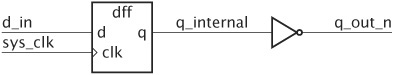
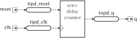
To illustrate how blocks can be used for partitioning a design, we develop a model for a counter, including detailed pin-to-pin propagation delays and some error checking. We can specify the propagation delays as combinations of input delays before the function block and output delays after the function block, as shown in Figure 23.1. The function block implements the behavior of the counter with zero delay.
The entity declaration for this counter is
entity counter is
 generic ( tipd_reset,             -- input prop delay on reset
           tipd_clk,               -- input prop delay on clk
           topd_q : delay_length;  -- output prop delay on q
           tsetup_reset,           -- setup: reset before clk
           thold_reset :           -- hold time: reset after clk
             delay_length );
 port ( reset,                     -- synchronous reset input
        clk : in bit;              -- edge-triggered clock input
        q : out bit_vector );      -- counter output
end entity counter;
We can separate the delay, function and error-checking aspects of the model into separate blocks within the architecture body, as follows:
   architecture detailed_timing of counter is
    signal reset_ipd,                   -- data input port delayed
           clk_ipd : bit;               -- clock input port delayed
    signal q_zd : bit_vector(q'range);  -- q output with zero delay
   begin
    input_port_delay : block is
    begin
      reset_ipd <= reset after tipd_reset;
      clk_ipd <= clk after tipd_clk;
    end block input_port_delay;

    functionality : block is

      function increment ( bv : bit_vector ) return bit_vector is
        variable result : bit_vector(bv'range) := bv;
        variable carry : bit := '1';
      begin
        for index in result'reverse_range loop
          result(index) := bv(index) xor carry;
          carry :=  bv(index) and carry;
          exit when carry = '0';
        end loop;
        return result;
      end function increment;
      signal next_count : bit_vector(q'range);
    begin
      next_count <= increment(q_zd) when reset_ipd = '0' else
                    (others => '0'),
      q_zd <= next_count when clk_ipd = '1' and clk_ipd'event;
    end block functionality;
    output_port_delay : block is
    begin
      q <= q_zd after topd_q;
    end block output_port_delay;
    timing_checks : block is
    begin
      -- check setup time: reset before clk
      ...
      -- check hold time: reset after clk
      ...
    end block timing_checks;

   end architecture detailed_timing;
The first block, input_port_delay, derives delayed versions of the input ports. These are used in the second block, functionality, the zero-delay behavioral implementation of the counter. This block consists of two concurrent signal assignment statements that together implement a finite-state machine. One statement calculates the next count value using the increment function locally declared within the block, and the other implements an edge-triggered register. The signal next_count, also locally declared within the block, is used to connect the two statements. The output of the state machine is used in the third block, output_port_delay, to apply the delay between the function block and the output port. The final block outlined in the architecture body, timing_checks, contains processes that verify correct setup and hold times for the reset signal.
Since a block contains a collection of concurrent statements, and a block statement is itself a concurrent statement, it is perfectly legal to nest blocks one inside another. The same visibility rules that we described for subprograms also apply for items declared in nested blocks. However, in practice, we would rarely write a model with nested blocks. If the design hierarchy is that complex, it is better to use separate entities and component instantiation statements to partition the design. The main reason VHDL allows complex nesting of blocks is that the block structure is used as the underlying mechanism for implementing other VHDL constructs, such as component instantiation (described in Chapter 13) and generate statements (described in Chapter 14). The language definition defines these constructs in terms of the substitution of blocks containing the contents of the architecture body being instantiated or the contents of the generate statement.
As we mentioned in Section 18.1, a block statement forms a concurrent region in a design. When we write external names, we need to include the label of a block in the pathname for any item declared in the block or in an entity instantiated in the block.
Example 23.6. Referring to a block in an external pathname
Suppose the counter design of Example 23.5 in instantiated with a test bench architecture. We can use an external name in the test bench to refer to the next_count signal. The test bench outline is as follows:
   architecture verifying of test_bench is

    signal clk, reset : bit;
    signal duv_q : bit_vector(7 downto 0);

    alias duv_next_count is
      <<signal duv.functionality.next_count :
                 bit_vector(duv_q'range)>>;
    ...
   begin
    duv : entity work.counter(detailed_timing)
      generic map ( ... )
      port map ( clk => clk, reset => reset, q => duv_q );
    ...
   end architecture verifying;
The counter is instantiated using the label duv. In the external name, the relative pathname starts with duv, followed by the block label functionality and then the signal name next_count.
Another aspect of block statements, also arising from their use as the underlying mechanism for component instantiation, is the possibility of including generic and port interface lists. These allow us to make explicit the interface between the block and its enclosing architecture body or enclosing block. The formal generics and ports can be used within the block in exactly the same way that those of an entity are used within a corresponding architecture body. The actual values for genericts are supplied by a generic map in the block header, and the actual signals associated with the formal ports are supplied by a port map. These are all shown in the syntax rule for block statements on page 744. Since this facility is rarely used in actual model writing, we do not dwell on it.
In Chapter 13 we showed how to configure a design whose hierarchy was formed by instantiating components. We configure an architecture body containing nested block statements in a similar way. When we write configuration declarations for such architecture bodies, the configuration information must mirror the block structure of the architecture body. We introduce a further level of detail in the syntax rules for configuration declarations, showing how to configure architecture bodies containing blocks.
   configuration_declaration  ⇐
      configuration identifier of entity_name is
          block_configuration
      end  [configuration] [identifier];
   block_configuration  ⇐
      for (architecture_name | block_statement_label)
           {   block_configuration
               |   for component_specification
                       [ binding_indication ; ]
                       [ block_configuration  ]
                  end for ; }
      end for ;
The difference here is that we have added a block statement label as an alternative to an architecture name at the point where we specify the region containing concurrent statements. Furthermore, we have allowed a block configuration as an alternative to component configuration information within that region. If we put these together, we can see how to write the configuration information for an architecture body containing block statements. At the top level of the configuration declaration, we write a block configuration naming the architecture body, just as we have done in all of the previous examples. Within it, however, we include block configurations that name and configure each block.
Example 23.7. Configuration of a design partitioned with blocks
Suppose we need to write a model for an integrated circuit that takes account of propagation delays through input and output pads. The entity declaration and architecture body are shown below. The architecture body is divided into blocks for input delay, function and output delay. The operation of the circuit is described structurally, as an interconnection of cells within the function block.
   entity circuit is
    generic ( inpad_delay, outpad_delay : delay_length );
    port ( in1, in2, in3 : in bit;  out1, out2 : out bit );
   end entity circuit;
   --------------------------------------------------
   architecture with_pad_delays of circuit is
    component subcircuit is
      port ( a, b : in bit;  y1, y2 : out bit );
    end component subcircuit;
    signal delayed_in1, delayed_in2, delayed_in3 : bit;
    signal undelayed_out1, undelayed_out2 : bit;
   begin
    input_delays : block is
    begin
      delayed_in1 <= in1 after inpad_delay;
      delayed_in2 <= in2 after inpad_delay;
      delayed_in3 <= in3 after inpad_delay;
    end block input_delays;
    functionality : block is
      signal intermediate : bit;
    begin
      cell1 : component subcircuit
        port map ( delayed_in1, delayed_in2,
                   undelayed_out1, intermediate );
      cell2 : component subcircuit
        port map ( intermediate, delayed_in3,
                   undelayed_out2, open );
    end block functionality;
    output_delays : block is
    begin
      out1 <= undelayed_out1 after outpad_delay;
      out2 <= undelayed_out2 after outpad_delay;
    end block output_delays;
   end architecture with_pad_delays;
A configuration declaration for this design is
   configuration full of circuit is
    for with_pad_delays -- configure the architecture
      for functionality    -- configure the block
        for all : subcircuit
          use entity work.real_subcircuit(basic);
        end for;
      end for;
    end for;
   end configuration full;
The configuration binds the instances of the component subcircuit within the block functionality to an entity real_subcircuit with architecture basic. The block configuration starting with “for with_pad_delays” specifies the architecture of circuit that is being configured. Within it, the block configuration starting with “for functionality” specifies the configuration of the contents of the block labeled functionality. It, in turn, contains a component configuration for the two component instances. Note that there are no block configurations for the other two blocks in the design, since they do not contain any component instances. They only contain concurrent signal assignment statements, which represent leaf nodes of the design hierarchy.
As designs become more complex, designers are increasingly using intellectual property (IP) provided by IP vendors. IP providers invest considerable effort in developing their products, and may be loath to release them without protecting their investment. From the IP provider’s point of view, there are two potential places where their IP may be compromised. First, the IP provider must transmit the IP to a customer. During that process, a malicious third party could eavesdrop on the transmission and intercept the IP. Second, the customer must receive, store, and use the IP. During that process, an unscrupulous customer could reuse the IP without compensating the provider. Hence, the customer is technically treated as a malicious third party, though it would not be politic to express the relationship in those terms! The real recipient of the IP is the customer’s tool, which must use the IP only in ways approved by the IP provider and must avoid disclosing the IP to the customer.
One way of protecting IP is for the provider to encrypt it in a form that can be decrypted and used by a customer’s tools, but that cannot be read by the customer. VHDL provides a flexible set of features to support such protection. Before we describe them in detail, we will first review some of the basic principles and protocols for encryption so that we can understand how to use the language features.
Information to be communicated between two parties can be protected by transforming it with a cipher. A cipher is a function that takes plain text and a string of bits called a key as input and produces cipher text as output. This process is called encryption. The reverse process, decryption, takes the cipher text and a key as input and reproduces the original plain text. The quality of a cipher is determined by the difficulty of determining the plain text from the cipher text without the key. A good cipher will yield significantly different cipher text for minor changes to the key used for encryption.
There are two forms of cipher in widespread use. A symmetric cipher uses the same key for both encryption and decryption. The key is called a secret key, since it must be kept secret between the communicating parties. Should the secret be revealed to a third party, they could decrypt any intercepted encrypted information. Examples of symmetric ciphers are the Data Encryption Standard (DES), and the Advanced Encryption Standard (AES).
An asymmetric cipher uses a pair of related keys, one for encryption and the other for decryption. Key pairs are generated in such a way that it is infeasible to determine either key from the other. Information encrypted with one key of a pair can only be decrypted with the other key of the pair. Examples of asymmetric ciphers are RSA and ElGamal. Asymmetric ciphers are used in protocols where each communicating party generates a key pair. They keep one key of the pair, the private key, secret. They publish the other key, the public key, through some means of dissemination that associates the public key with the communicating party’s identity. For example, they might publish it on their website. A sender of information can use an asymmetric cipher to protect information destined for a recipient. The sender encrypts the information using the recipient’s public key. Only the recipient can then decrypt the information, since only they have the corresponding private key.
While asymmetric ciphers can yield more secure communication, they involve significantly greater computation than symmetric ciphers. For that reason, most applications involving asymmetric ciphers use a two-stage encryption process called a digital envelope. First a session key is randomly generated, for use in one communication session only. Next, that session key is used with a symmetric cipher to encrypt the information. In order to communicate the session key to the recipient so that they can decrypt the information, the session key is encrypted using an asymmetric cipher with the recipient’s public key, and sent to the recipient. They are the only party able to decrypt the session key, since only they have the right private key. They can then proceed to decrypt the communicated information using the symmetric cipher with the decrypted session key. The advantage of this approach is that only a relatively small amount of information (the session key) need be processed using the computationally intensive asymmetric cipher. The bulk of the information is processed using the lighter-weight symmetric cipher.
One problem that arises in protected communication is the need to verify that received information did in fact originate with the purported sender, and that it was not changed in transit (either by corruption or maliciously) by a third party. This problem is addressed by having the sender transmit a digital signature for the information. The sender uses a hash function to compute a digest of the information. A hash function takes a (potentially large) string of bits as input and produces a small string of bits, the digest, that depends on all of the input bits. A good hash function has the property that two distinct input strings are highly unlikely to yield the same output string. Examples of hash functions include SHA1, MD2, MD5, and RIPEMD. Having computed the digest of the information, the sender encrypts it using an asymmetric cipher with their private key and transmits the result as the digital signature. A recipient decrypts the signature using the purported sender’s public key to retrieve the digest. The recipient also independently calculates the digest of the received information using the hash function. If the two digests are the same, the information has been received correctly, since only the real sender’s public key could decrypt the digest correctly, and only the real information would yield the same digest. If, on the other hand, the digests differ, then either the transmitted digest was encrypted with someone else’s key, or the transmitted message was changed. Either way, the transmission was compromised, and the recipient knows not to trust the received information.
If we are to apply cryptographic techniques to transmission of VHDL models, we need to consider the way in which the encrypted information is encoded. Plain-text VHDL models consist of printable ASCII or Latin-1 characters and are immune to the way ends of lines are encoded. Consequently, we can store and transmit plain-text models through a variety of media without being concerned about encodings. However, the process of encryption produces a string of bits, which cannot be guaranteed to be interpreted as printable characters. We cannot reliably transmit the encrypted model, since some media might transform sequences of bits interpreted as line ends, or might interpret sequences of bits as in-band control codes. To avoid these problems, we can encode the encrypted model using an encoding method that uses printable characters to represent the string of bits. A sender encrypts information and encodes it for transmission, and a recipient decodes the received information and decrypts the result. Examples of encoding methods include uuencode, base64, and quoted-printable, all of which are described by Internet message-transfer standards.
With this overview of cryptography in hand, we can now discuss the features provided in VHDL to support cryptographic protection of IP. The features use a standard set of tool directives. A tool directive is an annotation included in a VHDL design file that provides information to a tool processing the VHDL design. It does not logically form part of the design itself. The syntax for a tool directive is
tool_directive ⇐ ‘identifier { graphic_character }
A tool directive starts with the “tick” symbol, and ends at the end of the line. The identifier specifies to the tool what form of processing to perform. The remaining text, up to the end of the line, provides any additional information needed.
For IP protection, VHDL defines protect directives, in which the identifier is protect. (Although the identifier is not a reserved word, we write it and other keywords in protect directives in boldface type to indicate that they have special meanings in the directives.) The protect directives are used by an IP provider’s encryption tool to govern encryption of sections of a VHDL design and by a customer’s decryption tool to decrypt those sections. The decryption tool is typically a simulator, synthesis tool, or some other tool that deals with VHDL code. It uses the decrypted sections of the design, but does not store them in any form that could be revealed to the customer. Protect directives each takes one of three forms:
   'protect keyword
   'protect keyword = value
   'protect keyword = ( keyword = value, ... )
The keyword or keywords in a protect directive identify the kind of information conveyed by the directive. The values are literal expressions of various types. If we have a number of consecutive protect directives, we can merge them into a single directive. Thus, we can write the sequence of directives
   'protect keyword1 = value1
   'protect keyword2 = value2
   'protect keyword3
equivalently as
'protect keyword1 = value1, keyword2 = value2, keyword3
An IP provider starts the process by identifying one or more sections of a VHDL design file that they want to protect. They edit the design file to wrap each section in an encryption envelope, consisting of one or more protect directives at the start of the section, and a closing protect directive at the end of the section. The simplest form of encryption envelope is
   'protect begin
   ... -- protected source code in plain-text form
   'protect end
This simply delimits the protected source code, and assumes an encryption tool will use default information about the ciphers, keys and encoding for encryption. More elaborate encryption envelopes precede the begin directive with protect directives specifying ciphers, keys, encoding and other optional information.
The IP provider then processes the design file with an encryption tool to produce a version of the design file with each encryption envelope replaced by a corresponding decryption envelope of the following form:
   'protect begin_protected
   protect directives and encoded encrypted information
   'protect end_protected
We will use a series of examples to show how the various directives are used to form encryption and decryption envelopes for various use cases. In each case we will assume that the decryption tool has access to the required keys, and that the encryption tool knows about those keys. We will return to the topic of key exchange in Section 23.2.1.
Example 23.8. Simple encryption envelope with symmetric cipher
In one of the simplest use cases, an IP provider wants to provide protected IP to a customer for use with a single tool. We can use a symmetric cipher, for which the key is known to both the IP provider and to the customer’s decryption tool. The IP provider wraps the protected section in the source code in an encryption envelope, as follows:
   entity accelerator is
    port ( ... );
   end entity accelerator;
   architecture RTL of accelerator is
   'protect data_keyowner = "ACME IP User"
   'protect data_keyname  = "ACME Sim Key"
   'protect data_method   = "aes192-cbc"
   'protect encoding      = (enctype = "base64")
   'protect begin
    signal ...
   begin
    process ...
    ...
   'protect end
   end architecture RTL;
The IP provider leaves the information about the entity’s interface and the name of the architecture unprotected so that the customer can instantiate the design. The entire inner workings of the architecture, however, are not to be revealed to the customer. The data_keyowner and data_keyname directives specify identifiers that the encryption and decryption tools can use to retrieve the key. The data_method directive specifies the cipher to use for encryption and decryption, and the encoding directive specifies the method to use to encode the cipher text produced by the encryption tool.
The IP provider processes the original source code file with an encryption tool, which produces a modified file with the encryption envelope replaced by a decryption envelope:
   entity accelerator is
    port ( ... );
   end entity accelerator;

   architecture RTL of accelerator is
   'protect begin_protected
   'protect encrypt_agent      = "Encryptomatic"
   'protect encrypt_agent_info = "2.3.4a"
   'protect data_keyowner = "ACME IP User"
   'protect data_keyname  = "ACME Sim Key"
   'protect data_method   = "aes192-cbc"
   'protect encoding=(enctype="base64", line_length=40, bytes=4006)
   'protect data_block
   encoded cipher-text
   ...
   'protect end_protected
   end architecture RTL;
The encrypt_agent and encrypt_agent_info directives provide information about the encryption tool. This can help in tracking down any problems that might arise. The directives specifying the key, cipher, and encoding method are replicated in the decryption envelope. In the case of the encoding directive, further information about the maximum line length for the encoded cipher text and the number of bytes of cipher text is also provided. The encoded cipher text then starts immediately after the data_block directive. The end_protected directive marks the end of the decryption envelope.
Example 23.9. Digital envelope encrypted for a single customer
One of the problems with using a symmetric cipher to encrypt IP is that the risk of the secret key being divulged. We can avoid that risk by using a digital envelope to transmit the IP. The IP provider includes directives in the encryption envelope to specify a cipher and key to use to encrypt a session key. The IP provider can also specify the symmetric cipher to use to encrypt the data with the session key. The design file with the revised encryption envelope is
   entity accelerator is
    port ( ... );
   end entity accelerator;

   architecture RTL of accelerator is
   'protect key_keyowner = "ACME IP User"
   'protect key_keyname  = "ACME Sim Key"
   'protect key_method   = "rsa"
   'protect key_block
   'protect data_method  = "aes192-cbc"
   'protect encoding     = (enctype = "base64")
   'protect begin
    signal ...
   begin
    process ...
    ...
   'protect end
   end architecture RTL;
The key_keyowner and key_keyname directives specify identifiers that the encryption tool can use to retrieve the customer’s public key. The key_method directive specifies the cipher to use to encrypt the session key. The key_block directive marks the end of the key information. Its presence in the encryption envelope specifies use of a digital envelope, since the preceding key directives can be omitted, implying default values. The data_method directive specifies the cipher to use for encryption and decryption with the session key. The encoding directive specifies the method to use to encode both the encrypted session key and the encrypted section of the model.
The IP provider processes this source code file with an encryption tool, which generates a session key and produces a modified file with the encryption envelope replaced by a decryption envelope specifying a digital envelope:
   entity accelerator is
    port ( ... );
   end entity accelerator;

   architecture RTL of accelerator is
   'protect begin_protected
   'protect encrypt_agent      = "Encryptomatic"
   'protect encrypt_agent_info = "2.3.4a"
   'protect key_keyowner = "ACME IP User"
   'protect key_keyname  = "ACME Sim Key"
   'protect key_method   = "rsa"
   'protect encoding=(enctype="base64", line_length=40, bytes=256)
   'protect key_block
   encoded cipher-text for session key
   'protect data_method   = "aes192-cbc"
   'protect encoding=(enctype="base64", line_length=40, bytes=4006)
   'protect data_block
   encoded cipher-text for model code
   ...
   'protect end_protected
   end architecture RTL;
The directives specifying the key and cipher for encrypting the session key are replicated in the decryption envelope. The encoding directive is also replicated to specify the encoding for the encrypted session key, augmented with information about the maximum line length for the encoded cipher text and the number of bytes in the encrypted session key. The encoded cipher text for the session key then starts immediately after the key_block directive. Next, the data_method directive specifying the cipher for the model code is replicated in the decryption envelope. The encoding directive is also replicated here, augmented with information about the maximum line length and the number of bytes. The encoded cipher text for the model code starts immediately after the data_block directive. The end_protected directive marks the end of the decryption envelope.
Example 23.10. Digital envelope encrypted for multiple customers or tools
In Example 23.8 and Example 23.9, the IP is encrypted in a form that can be decrypted by a single customer or by a single tool. If the IP provider wants to distribute the IP to multiple customers or to a customer for use with multiple tools, he or she would have to generate multiple versions using the encryption tool, once per customer. We can avoid this repetition by using a variation on the digital envelope approach. Again, we specify that a session key be used to encrypt the model code. However, that session key is then encrypted multiple times, once per customer or customer’s tool. The revised source file with the encryption envelope is
   entity accelerator is
    port ( ... );
   end entity accelerator;

   architecture RTL of accelerator is
   'protect key_keyowner = "ACME IP User1"
   'protect key_keyname  = "ACME Sim Key"
   'protect key_method   = "rsa"
   'protect key_block
   'protect key_keyowner = "ACME IP User2"
   'protect key_keyname  = "ACME Synth Key"
   'protect key_method   = "elgamal"
   'protect key_block
   'protect key_keyowner = "ACME IP User3"
   'protect key_keyname  = "ACME P&R Key"
   'protect key_method   = "aes192-cbc"
   'protect key_block
   'protect data_method  = "aes192-cbc"
   'protect encoding     = (enctype = "base64")
   'protect begin
    signal ...
   begin
    process ...
    ...
   'protect end
   end architecture RTL;
Each group of key directives specifies information for encryption of a session key for decryption by a given decryption tool. The first two groups specify encryption using asymmetric ciphers, as is normally done in digital envelopes. However, we can also use a symmetric cipher to encrypt the session key, as specified in the third group of key directives.
As in the earlier examples, the IP provider processes this source code file with an encryption tool, which generates a session key and produces a modified file with the encryption envelope replaced by a decryption envelope specifying a digital envelope:
   entity accelerator is
    port ( ... );
   end entity accelerator;
   architecture RTL of accelerator is
   'protect begin_protected
   'protect encrypt_agent      = "Encryptomatic"
   'protect encrypt_agent_info = "2.3.4a"
   'protect key_keyowner = "ACME IP User1"
   'protect key_keyname  = "ACME Sim Key"
   'protect key_method   = "rsa"
   'protect encoding=(enctype="base64", line_length=40, bytes=256)
   'protect key_block
   encoded cipher-text for session key
   'protect key_keyowner = "ACME IP User2"
   'protect key_keyname  = "ACME Synth Key"
   'protect key_method   = "elgamal"
   'protect encoding=(enctype="base64", line_length=40, bytes=256)
   'protect key_block
   encoded cipher-text for session key
   'protect key_keyowner = "ACME IP User3"
   'protect key_keyname  = "ACME P&R Key"
   'protect key_method   = "aes192-cbc"
   'protect encoding=(enctype="base64", line_length=40, bytes=256)
   'protect key_block
   encoded cipher-text for session key
   'protect data_method   = "aes192-cbc"
   'protect encoding=(enctype="base64", line_length=40, bytes=4006)
   'protect data_block
   encoded cipher-text for model code
   ...
   'protect end_protected
   end architecture RTL;
In this case, the decryption envelope includes a group of key directives and a key block corresponding to each group of key directives in the encryption envelope. Each of the targeted decryption tools, when it processes the decryption envelope, checks whether it has access to the key specified by each group of key directives. If it has one of the keys, it can use that key to decrypt the session key, and thus decrypt the model code.
Example 23.11. Digital signature for authentication of the provider
Suppose our IP provider delivers encrypted IP by making it available for download from a file server. They use our public key to deliver the IP in digital envelope form. An unscrupulous third-party IP provider could seek to besmirch the name of our trusted IP provider by spoofing their server and providing a buggy version of the IP. Since the IP is encrypted using our public key, which is widely known, we would not be aware of the switch.
The solution is for our trusted IP provider to include a digital signature in the delivered model. The encryption envelope, revised from that in Example 23.10, is
   entity accelerator is
     port ( ... );
   end entity accelerator;

   architecture RTL of accelerator is
   'protect key_keyowner = "ACME IP User"
   'protect key_keyname  = "ACME Sim Key"
   'protect key_method   = "rsa"
   'protect key_block
   'protect data_method  = "aes192-cbc"
   'protect digest_keyowner   = "GoodGuys IP Author"
   'protect digest_keyname    = "GoodGuys Signing Key"
   'protect digest_key_method = "rsa"
   'protect digest_method     = "sha1"
   'protect digest_block
   'protect encoding = (enctype = "base64")
   'protect begin
     signal ...
   begin
      process ...
      ...
    'protect end
   end architecture RTL;
The digest directives in the encryption envelope specify that a digital signature should be generated for the model code contained in the envelope. The digest_method directive specifies the hash function for computing the digest, and the digest_keyowner, digest_keyname and digest_key_method directives specify the cipher and key to use to encrypt the digest. The digest_key_method directive must specify an asymmetric cipher, since digital signatures are predicated on the use of such ciphers.
The IP provider processes this source code file with an encryption tool, which computes and encrypts the digest to form the digital signature. It uses the private key of the key pair specified by the digest key directives. It includes the digest in the decryption envelope corresponding to the encryption envelope:
   entity accelerator is
     port ( ... );
   end entity accelerator;

   architecture RTL of accelerator is
   'protect begin_protected
   'protect encrypt_agent      = "Encryptomatic"
   'protect encrypt_agent_info = "2.3.4a"
   'protect key_keyowner = "ACME IP User"
   'protect key_keyname  = "ACME Sim Key"
   'protect key_method   = "rsa"
   'protect encoding=(enctype="base64", line_length=40, bytes=256)
   'protect key_block
   encoded cipher-text for session key
   'protect data_method   = "aes192-cbc"
   'protect encoding=(enctype="base64", line_length=40, bytes=4006)
   'protect data_block
   encoded cipher-text for model code
   ...
   'protect digest_keyowner   = "GoodGuys IP Author"
   'protect digest_keyname    = "GoodGuys Signing Key"
   'protect digest_key_method = "rsa"
   'protect digest_method     = "sha1"
   'protect digest_block
   'protect encoding=(enctype="base64", line_length=40, bytes=16)
   'protect digest_block
   encoded cipher-text for digest
   ...
   'protect end_protected
   end architecture RTL;
Our trusted IP provider places this model on the file server for us to download. Now suppose the unscrupulous third-party IP provider performs their network hack and substitutes a buggy model. In their first attempt, they substitute the buggy code, encrypted with a session key that they generate, and encrypt the session key with our public key. Our decryption tool successfully decrypts the session key and uses it to decrypt the model. However, since we want to verify that we have the right model, the decryption tool computes the digest of the decrypted model using the hash function specified in the digest_method directive. The tool also uses the public key of the key pair identified in the digest key directives to decrypt the transmitted digest. Since the model code is different from the original code provided by the trusted IP provider, the two digests are not the same. Our decryption tool alerts us to this fact, and we contact our trusted IP provider to attempt to remedy the problem.
Now suppose the unscrupulous third-party IP provider realizes their ruse was unsuccessful, and tries a different tack. As well as substituting the buggy model, suitably encrypted, they also generate a digital signature for the buggy model and substitute it for the real digital signature. They use their own private key to encrypt the digest, and include digest key directives that identify their key pair. Again, our decryption tool successfully decrypts the model and calculates the digest. The tool also attempts to decrypt the transmitted digest in order to compare with the computed digest. At this point, there are two possible outcomes. First, if the tool does not have access to the unscrupulous provider’s public key, it will be unable to proceed and will warn us that it could not verify the digital signature. Alternatively, if the tool does have access to the unscrupulous provider’s public key, it will use it to decrypt the transmitted digest and compare it with the computed digest. In this case, the digests will match. It will be up to us to check that signature verification was performed with the key we expected. This illustrates that we need to be vigilant when checking digital signatures, so that we are not duped by a simple key substitution. We will discuss this more in Section 23.2.1, where we address the issue of key exchange.
Example 23.12. Viewport for accessing a declaration in a protected model
An IP provider may wish to allow limited access to some items declared within the protected source code. In Examples 18.2 and 18.3 in Section 18.1, we showed a test bench monitoring the internal state of the control section of a design under verification. An IP provider can allow such access by including a viewport directive in the encryption envelope. An example is
   entity accelerator is
     port ( ... );
   end entity accelerator;

   architecture RTL of accelerator is
   'protect data_keyowner = "ACME IP User"
   'protect data_keyname  = "ACME Sim Key"
   'protect data_method   = "aes192-cbc"
   'protect encoding      = (enctype = "base64")
   'protect viewport=(object="accelerator:RTL.state", access="RW");
   'protect begin
     signal state : std_ulogic_vector(3 downto 0);
    ...
   begin
    process ...
    ...
   'protect end
   end architecture RTL;
While most of the inner workings of the architecture are not revealed to the customer, the viewport directive provides the pathname of the object representing the internal state signal and grants read/write access. The IP provider processes the source code file with an encryption tool, which includes the viewport directive in the decryption envelope:
   entity accelerator is
     port ( ... );
   end entity accelerator;

   architecture RTL of accelerator is
   'protect begin_protected
   'protect encrypt_agent      = "Encryptomatic"
   'protect encrypt_agent_info = "2.3.4a"
   'protect viewport=(object="accelerator:RTL.state", access="RW");
   'protect data_keyowner = "ACME IP User"
   'protect data_keyname  = "ACME Sim Key"
   'protect data_method   = "aes192-cbc"
   'protect encoding=(enctype="base64", line_length=40, bytes=4006)
   'protect data_block
   encoded cipher-text
   ...
   'protect end_protected
   end architecture RTL;
The customer can instantiate the IP in a design and use an external name to refer to the state signal:
   architecture monitoring of tb is
    ...
   begin
    ... -- clock and reset generation

    accelerator_duv : entity work.accelerator(rtl)
      port map ( ... );

    monitor : process (clk) is
      use std.textio.all;
      file state_file : text open write_mode is state_file_name;
      alias accelerator_state is
        <<signal accelerator_duv.state :
                   std_ulogic_vector(3 downto 0)>>;
    begin
      if falling_edge(clk) then
        write(L, accelerator_state); writeline(state_file, L);
      end if;
    end process monitor;
   end architecture monitoring;
While the viewport directive provides access to the internal signal, it does not provide complete information. The IP provider would also need to provide documentation describing the type of the signal and other relevant information.
Now that we have seen how protection envelopes are formed in various scenarios, we will describe the details of VHDL’s IP protection mechanism. As we have mentioned, it is based on a set of tool directives. The full list of directives is as follows:
‘protect beginIndicates the beginning of the source code to be encrypted in an encryption envelope.
Indicates the end of an encryption envelope.
‘protect begin_protectedIndicates the beginning of a decryption envelope.
‘protect end_protectedIndicates the end of a decryption envelope.
‘protect author= “author name”Identifies the author of the protected IP. If this directive appears in an encryption envelope, the encryption tool copies it unchanged to the corresponding decryption envelope.
‘protect author_info= “author info”Provides further information about the author of the protected IP, such as an organization name or contact details. If this directive appears in an encryption envelope, the encryption tool copies it unchanged to the corresponding decryption envelope.
‘protect encrypt_agent= “encrypt agent name”This directive must appear in a decryption envelope, and identifies the encryption tool that produced the decryption envelope.
‘protect encrypt_agent_info= “encrypt agent info”This directive may appear in a decryption envelope, and provides further information about the encryption tool that produced the decryption envelope.
‘protect key_keyowner= “key owner name”Identifies the owner of a key or key pair used to encrypt a session key.
‘protect key_keyname= “key name”Used together with the key owner name to identify a particular key or key pair used to encrypt a session key.
‘protect key_method= “cipher name”Specifies the cipher used to encrypt a session key.
‘protect key_blockIn an encryption envelope, specifies use of a digital envelope. In the corresponding decryption envelope, indicates the beginning of the encoded cipher text of the session key.
‘protect data_keyowner= “key owner name”Identifies the owner of a key or key pair used to encrypt the source code.
‘protect data_keyname= “key name”Used together with the key owner name to identify a particular key or key pair used to encrypt the source code.
‘protect data_method= “cipher name”Specifies the cipher used to encrypt the source code.
‘protect data_blockIn a decryption envelope, indicates the beginning of the encoded cipher text of the source code.
‘protect digest_keyowner= “key owner name”Identifies the owner of the key pair used to encrypt the digest in a digital signature.
‘protect digest_keyname= “key name”Used together with the key owner name to identify a particular key pair used to encrypt the digest in a digital signature.
‘protect digest_key_method= “cipher name”Specifies the asymmetric cipher used to encrypt the digest in a digital signature.
‘protect digest_method= “hash function name”Specifies the hash function used to compute the digest in a digital signature.
‘protect digest_blockIn an encryption envelope, specifies use of a digital signature. In the corresponding decryption envelope, indicates the beginning of the encoded cipher text of the digest.
‘protect encoding= (enctype= “encoding name”,line_length=integer,bytes=integer)In an encryption envelope, this directive specifies the encoding to be used for cipher text in the corresponding decryption envelope. The
line_lengthkeyword and value are optional and specify the maximum line length for encoded text. Text longer than this amount is split into multiple lines. Thebyteskeyword and value are also optional and are ignored in an encryption envelope in any case.In a decryption envelope, this directive appears preceding each key, data, and digest block. It specifies the encoding, maximum line length, and number of bytes of cipher text encoded in the block.
‘protect viewport= (object= “object pathname”,access= “access type”)Identifies an object declared within the protected source code for which access is granted. If this directive appears in an encryption envelope, the encryption tool copies it unchanged to the corresponding decryption envelope.
The pathname consists of the names of regions enclosing the declaration, starting with the design unit name and continuing with the names of nested regions, separated by “.” characters, for example,
"my_entity.cycle_monitor.cycle_count"
If the object is declared within an architecture, the design unit name is the combination of the entity name and the architecture name, separated by a colon, for example,
"my_entity:RTL.current_state"
If the object is declared within a package body, the design unit name consists of the package name, followed by “
:body”, for example,"IP_pkg:body.trace_file"
The access type string must be one of “
R”, “W”, or “RW”(or the lowercase equivalents), indicating read access, write access, or read/write access, respectively.'protect decrypt_license = ( library = "library name", entry = "acquisition routine name", feature = "feature name", exit = "release routine name", match = integer )
This directive specifies information for acquiring a decryption license. If the directive appears in an encryption envelope, the encryption tool copies it unchanged to the corresponding decryption envelope. If the directive appears in a decryption envelope, a decryption tool must attempt to acquire the specified license. If acquisition is successful, it continues decrypting the model. Otherwise, it is expected to stop further decryption.
The library name string identifies the object library in the decryption tool’s host file system containing routines for license management. The tool should call the routine identified by the acquisition routine name, passing the feature name string as an argument, to acquire a license. The tool should compare the return value of the routine with the match integer. If they are equal, acquisition succeeded. When the tool has completed decryption, it should relinquish the license by calling the routine identified by the release routine name.
'protect runtime_license =
( library = "library name",
 entry = "acquisition routine name", feature = "feature name",
 exit = "release routine name", match = integer )
This directive specifies information for acquiring a runtime license. If the directive appears in an encryption envelope, the encryption tool copies it unchanged to the corresponding decryption envelope. If the directive appears in a decryption envelope, a decryption tool must attempt to acquire the specified license. If acquisition is successful, the tool may continue with analysis and execution of the model. Otherwise, it is expected not to execute the model. The information in this directive is the same as that in a
decrypt_licensedirective.‘protect comment= “comment string”This directive allows the IP author to provide comments in the model. If the directive appears in an encryption envelope, either preceding or within the source code, the encryption tool copies it unchanged to the corresponding decryption envelope. If it is within the source code, the encryption tool skips over it when encrypting the source code.
Note, incidentally, that we have split a number of the longer directives over multiple lines, for reasons of presentation here. In practice, each directive must appear entirely on one line in a VHDL model.
Several directives use strings to specify ciphers, encodings, and hash functions. VHDL defines particular string values for these directives. If a tool supports the given cipher, encoding, or hash function, it must use the defined string value to specify it. A tool may also support other methods, in which case it uses an implementation-defined string value. Table 23.1 shows the string values for specifying ciphers. Every tool must support at least the DES cipher. Table 23.2 shows the string values for specifying encodings. Every tool must support at least uuencode and base64. Table 23.3 shows the string values for specifying hash functions. Every tool must support at least SHA1 and MD5.
Table 23.1. Strings for specifying ciphers
String | Cipher | Cipher type |
|---|---|---|
“des-cbc” | DES in CBC mode. | Symmetric |
“3des-cbc” | Triple DES in CBC mode. | Symmetric |
“aes128-cbc” | AES in CBC mode with 128-bit key. | Symmetric |
“aes192-cbc” | AES in CBC mode with 192-bit key. | Symmetric |
“aes256-cbc” | AES in CBC mode with 256-bit key. | Symmetric |
“blowfish-cbc” | Blowfish in CBC mode. | Symmetric |
Twofish in CBC mode with 128-bit key. | Symmetric | |
“twofish192-cbc” | Twofish in CBC mode with 192-bit key. | Symmetric |
“twofish256-cbc” | Twofish in CBC mode with 256-bit key. | Symmetric |
“serpent128-cbc” | Serpent in CBC mode with 128-bit key. | Symmetric |
“serpent192-cbc” | Serpent in CBC mode with 192-bit key. | Symmetric |
“serpent256-cbc” | Serpent in CBC mode with 256-bit key. | Symmetric |
“cast128-cbc” | CAST-128 in CBC mode. | Symmetric |
“rsa” | RSA. | Asymmetric |
“elgamal” | ElGamal. | Asymmetric |
“pgp-rsa” | OpenPGP RSA key. | Asymmetric |
Table 23.2. Strings for specifying encodings
String | Encoding methods |
|---|---|
“uuencode” | IEEE Std 1003.1™-2001 (uuencode Historical Algorithm) |
“base64” | IETF RFC 2045, also IEEE Std 1003.1 (uuencode -m) |
“quoted-printable” | IETF RFC 2045 |
“raw” | Identity transformation; no encoding is performed, and the data may contain non-printing characters. |
Table 23.3. Strings for specifying hash functions
Digest method string | Required/optional | Hash function |
|---|---|---|
“sha1” | Required | Secure Hash Algorithm 1 (SHA-1). |
“md5” | Required | Message Digest Algorithm 5. |
“md2” | Optional | Message Digest Algorithm 2. |
“ripemd-160” | Optional | RIPEMD-160. |
We can now describe the rules for forming an encryption envelope in a model. The rules allow for considerable flexibility, but we must at least include the begin and end directives to mark out the source code to be encrypted.
We can precede the begin directive with a key_block directive if we want to specify use of digital envelopes. We can specify the cipher and key to use to encrypt the session key by including a key_method and a key_keyowner directive (and optionally a key_keyname directive). If we don’t specify the cipher and key, the encryption tool chooses a default cipher and key. The key_method, key_keyowner and key_keyname directives can appear in any order, but must immediately precede the key_block directive. We can include more than one group of key-related directives, as we described in Example 23.10.
We can also precede the begin directive with a data_method directive if we want to specify the cipher to use to encrypt the source code. If we are not using digital envelopes and we include a data_method directive, we must also include a data_keyowner directive and optionally a data_keyname directive to identify the key. If we are using digital envelopes, the encryption tool generates the session key, so we do not include directives to identify the key. If we omit the data_method directive, the encryption tool chooses a default cipher. All of the directives relating to encryption of the source code must appear together in an encryption envelope.
If we want to include a digital signature, we precede the begin directive with a digest_block directive. We can specify the cipher and key to use to encrypt the digest by including a digest_key_method and a digest_keyowner directive (and optionally a digest_keyname directive). If we don’t specify the cipher and key, the encryption tool chooses a default cipher and key. Similarly, we can specify the hash function to use by including a digest_method directive. If we don’t specify a hash function, the encryption tool chooses a default hash function. The digest_key_method, digest_keyowner, digest_keyname, and digest_method directives can appear in any order, but must immediately precede the digest_block directive.
Beyond these specifications, we can include directives to identify the IP author, describe licenses and viewports, and specify the encoding to use. If we don’t specify the encoding, the encryption tool chooses a default encoding. We can also include comment directives anywhere within the encryption envelope, including in the source code between the begin and end directives.
The rules that an encryption tool must follow to form a decryption envelope are somewhat more prescriptive. Groups of directives must appear in a specified order, even if the corresponding directives in the encryption envelope appeared in a different order or distributed among other directives, though not all groups are required in every decryption envelope. The layout of a decryption envelope is
   'protect begin_protected
   author directives
   license directives
   encrypt agent directives
   viewport directives
   key block directives
   data block directives
   digest block directives
   'protect end_protected
The author, license, and viewport directives are those that appear in the encryption envelope, if any. The encrypt_agent directive and optionally and encypt_agent_info directive are included by the encryption tool. If a digital envelope is used, there is a group of key block directives for each encryption of the session key. The directives occur in the following order, with only the key_keyname directive being optional:
   key_keyowner directive
   key_keyname directive
   key_keymethod directive
   encoding directive
   key_block directive
   encoded cipher text for session key
The data block directives occur in the following order, with the data_keyowner and (optional) data_keyname directives only appearing if a digital envelope is not being used:
   data_keyowner directive
   data_keyname directive
   data_method directive
   encoding directive
   data_block directive
   encoded cipher text for source code
If a digital signature is used, the digest block directives occur in the following order, with only the digest_keyname directive being optional:
   digest_keyowner directive
   digest_keyname directive
   digest_key_method directive
   digest_method directive
   encoding directive
   digest_block directive
   encoded cipher text for digest
In our description of IP exchange so far we have assumed that the IP provider’s encryption tool and the customer’s decryption tool each have the required keys. What we have glossed over is how the tools get the keys. This is a very important topic, since protection of IP from disclosure relies on the security of the encryption and decryption keys. Should a key become known to an unauthorized party, the encrypted IP can be decrypted and disseminated. Normally, when encryption is used to secure communication between two parties, the parties are assumed to have an interest in the security of the encrypted messages and can be trusted to keep the keys secret. However, as we mentioned earlier, when an IP provider delivers a model to a customer, it is the customer’s tool that is really the communicating party. The IP provider may not trust the customer not to look at the code or use it in some unauthorized way. A further complication is that the customer may have to provide his or her tool’s key to an IP provider, creating an opportunity for the customer to copy the key and subsequently decrypt the code. Given these considerations, we can see that exchange of keys can be quite complicated. VHDL does not specify how keys should be exchanged; that is left to negotiation between IP providers, tool vendors, and customers. The following discussion, drawn from the VHDL standard, explores some of the issues.
Many applications that require secure exchange of keys rely on public key infrastructure (PKI). Parties to communication generate, or are given, key pairs for use with asymmetric ciphers. Each party keeps their private key secret, and publishes their public key, for example, in a directory. In order to establish that a public key does, in fact, belong to a given party, the public key is digitally signed by a trusted authority. The signed public key is represented in the form of a digital certificate, containing the key and the signature. The trusted authority is called a certification authority (CA). Many PKI systems have a hierarchy of CAs, allowing a certificate signed by a subordinate CA to be signed by a superior CA, allowing trust to be distributed hierarchically. One or more root CAs are required to be globally trusted.
Key exchange for IP protection may be built upon public key infrastructure. For example, a vendor of a decryption tool may embed a private key of a key pair in the tool and register the public key with a CA. The tool can then generate a key pair for the tool’s user, keeping the private key secret and signing the public key with both the vendor’s private key and the user’s private key. This allows verification that the public key originates with the instance of the vendor’s tool owned by the tool user. That public key may then be used by IP authors to provide IP for that use of that tool only. Similar mechanisms might also be employed within tools to allow exchange of private keys among tools without disclosure to the tools’ user.
In addition to providing for secure key exchange, a decryption tool must take measures to ensure that stored keys are not disclosed to the tool user. If a tool user could read a tool’s stored keys, the user could decrypt IP independently of the tool. One way of ensuring security of a tool’s keys is for the tool to encrypt its key store using a secret key embedded in the tool in a disguised manner, and to provide for update and re-encryption of the secret key in case it is compromised.
VHPI is an application-programming interface (API) to VHDL tools. Using VHPI, a program written in a language such as C or C++ can access information about a VHDL model during analysis, elaboration, and execution of the model. VHPI allows development of add-in tools, such as linters, profilers, code coverage analyzers, timing and power analyzers, and external models, among others. Use of the VHPI to develop such tools is quite complex, and is beyond the scope of this book. Instead, we will describe the way in which we can invoke VHPI programs as part of a VHDL simulation.
VHPI programs are divided into two classes: foreign models and foreign applications. A foreign model corresponds to an architecture or a subprogram decorated with the ’foreign attribute, predefined in the package standard as follows:
attribute foreign : string;An architecture or subprogram decorated with this attribute is not elaborated or executed in the same way as a normal architecture or subprogram. Instead, the value of the attribute is used to identify the VHPI program that implements the behavior of the architecture or subprogram, respectively.
A foreign application does not have a counterpart in the VHDL code. It is executed as part of simulation and performs application-specific processing. Both forms of VHPI program can use API calls to obtain information about the VHDL model, to react to changes in the simulation state, and to cause changes in the simulation state.
VHDL-87, -93, and -2002
These versions of VHDL do not provide a standard API for foreign models or applications. Instead, simulation vendors have provided proprietary APIs for use with their tools. Such APIs are not portable between tools.
VHDL-87
The predefined attribute ‘foreign is not provided in VHDL-87. There is no standard mechanism to define foreign language interfaces.
If we are to instantiate a foreign model as part of a VHPI design, we need to identify where the VHPI program code is to be found. Typically, the provider of the foreign model would provide documentation listing the names of libraries and functions to which we should refer. The most straightforward method of referring to the VHPI program code is to provide the information in the value of the ‘foreign attribute in a form known as direct binding. For a foreign architecture, we write the attribute value in the following form:
"VHPIDIRECT object_lib_path elab_function exec_function"
The keyword VHPIDIRECT specifies standard direct binding, and must be written in uppercase. The object_lib_path is a host-dependent path and file name identifying the binary object library in the host file system. It can contain any characters; however, if a space character is required, we must precede it with a backslash character, and if a backslash character is required, we must double the backslash. The elab_function is the name of a function within the object library that performs elaboration for the foreign architecture. It is called to elaborate each instance of the foreign architecture during elaboration of the enclosing design. The exec_function is similarly the name of a function in the object library that performs simulation for the foreign architecture. It is called once for each instance of the foreign architecture during the initialization phase of simulation.
In the attribute value, we can substitute the keyword null for the object library path. In that case, the host system locates the object library in an implementation-dependent way. It might, for example, use an environment variable containing a list of pathnames. We can also substitute the keyword null for the elaboration function name if the foreign model does not require any action during elaboration. In both cases, the keyword null must be written in lowercase.
Example 23.13. Foreign processor core model
Suppose a foreign model for a CPU32 processor core is provided in an object library called cpu32.a that we have installed in the directory /usr/local/cpu32. The elaboration and execution functions for a bus-functional version are named cpu32_bf_elab_f and cpu32_bf_exec_f, respectively. An entity and architecture that use standard direct binding for the bus-functional version are:
   entity cpu32 is
     generic ( ... );
     port ( ... );
   end entity cpu_32;

   architecture bus_functional of cpu32 is
     attribute foreign of bus_functional : architecture is
       "VHPIDIRECT /usr/local/cpu32/cpu32.a " &
       "cpu32_bf_elab_f cpu32_bf_exec_f";
    begin
   end architecture bus_functional;
The attribute value for standard direct binding for a foreign subprogram takes a similar form:
"VHPIDIRECT object_library_path exec_function"
In this case, the execution function name identifies a function that performs the action of the foreign subprogram. It is called whenever the foreign subprogram is called during simulation. For foreign subprograms, we can substitute the keyword null for the execution function name. In that case, the execution function name is taken to be the same as that of the foreign subprogram declared in the VHDL model, using the case of letters in the VHDL declaration.
Example 23.14. Foreign display subprograms
Suppose we are given subprograms that show 7-segment display digits graphically on the screen during simulation. The subprograms are in the library displaylib.a, and include a function named create_digit and a procedure named update_digit. We can declare corresponding foreign subprograms in a package as follows:
   package display_pkg is

     impure function create_digit (title : in string)
                                  return natural;
     attribute foreign of create_digit : function is
       "VHPIDIRECT displaylib.a null";
    procedure update_digit (id : in natural;
                            val : in bit_vector(0 to 7));
    attribute foreign of update_digit : procedure is
       "VHPIDIRECT displaylib.a null";
   end package display_pkg;
An alternative way of identifying the VHPI program code for a foreign model is to use a tabular registry, which is a text file containing the identifying information. A tool can be supplied with any number of tabular registry files, each describing one or more foreign models or applications. The way in which we specify use of a tabular registry file is tool-dependent. It might, for example, involve use of a command-line option or an entry in an options-setting file. Each line of a tabular registry is an entry describing one foreign model, foreign application, or library of VHPI programs. The file can also contain comment lines, starting with characters “--”, and blank lines.
A foreign architecture is described by a line of the following form in a tabular registry:
object_lib_name model_name vhpiArchF elab_function exec_function
The object_lib_name is a logical name for the binary object library containing the VHPI program code. The host system maps the logical name to a physical object library in some host-dependent way. The model_name is an identifier for the foreign architecture in the object library. Both the library logical name and the model name can be written as a normal identifier or, if non-standard characters are required, as an extended identifier delimited by backslash characters. The keyword vhpiArchF indicates that the line in the tabular registry describes a foreign architecture. It must be written using the combination of uppercase and lowercase letters shown here. The elab_function and exec_function are the names of the elaboration function and execution function, respectively, in the object library. They serve the same purpose as described in Section 23.3.1, and, in a similar way, the elaboration function name can be replaced by the keyword null.
Having described a foreign architecture in a tabular registry file, we can specify a ‘foreign attribute in the form of an indirect binding to use the foreign architecture for a VHDL architecture. This form of attribute value is
"VHPI object_lib_name model_name"
The object_lib_name and model_name identifiers must correspond to the library logical name and model name identifiers specified in an entry in a tabular registry. The foreign architecture described in that entry is used for each instance of the VHDL architecture decorated with the attribute.
Example 23.15. Foreign processor core model using indirect binding
Suppose the provider of the CPU32 processor core model described in Example 23.13 also provides a tabular registry file for binding the bus-functional model. The file contains the following entry:
cpu32lib cpu32-bf vhpiArchF cpu32_bf_elab_f cpu_bf_exec_fWe decorate the architecture with the ‘foreign attribute using indirect binding for the bus-functional model:
   architecture bus_functional of cpu32 is
     attribute foreign of bus_functional : architecture is
       "VHPI cpu32lib cpu32-bf";
   begin
   end architecture bus_functional;
Tabular registration and indirect binding for a foreign subprogram are similar. An entry in a tabular registry file for a foreign procedure takes the form:
object_lib_name model_name vhpiProcF null exec_function
and for a foreign function:
object_lib_name model_name vhpiFuncF null exec_function
In both cases, the object_lib_name and model_name serve the same purpose as for a foreign architecture, and the exec_function is the name of the function in the object library that implements the subprogram’s actions. The function name can be replaced by the keyword null, in which case the execution function is taken to be the same as the model name. The ’foreign attribute value for indirect binding to a foreign subprogram is the same as that for indirect binding to a foreign architecture, namely,
"VHPI object_lib_name model_name"
The library name and model name are used in the same way to locate the tabular registry entry for the foreign subprogram.
Example 23.16. Foreign display subprograms using indirect binding
The provider of the display subprograms described in Example 23.14 might provide a tabular registry file for the subprograms including the following entries:
   displaylib create_digit vhpiFuncF null null
   displaylib update_digit vhpiProcF null null
The second null in each entry indicates that the execution function names for the subprograms are the same as the foreign model names, namely, create_digit and update_digit. We declare the foreign subprograms and use indirect binding in the ‘foreign attribute values as follows:
   package display_pkg is

    impure function create_digit (title : in string)
                                  return natural;

    attribute foreign of create_digit : function is
     "VHPI displaylib create_digit";

    procedure update_digit (id : in natural;
                             val : in bit_vector(0 to 7));

    attribute foreign of update_digit : procedure is
      "VHPI displaylib update_digit";

   end package display_pkg;
We can use the tabular registration feature described in Section 23.3.2 to describe a VHPI application to be run as part of a simulation. A line in the file for a foreign application takes the form:
object_lib_name application_name vhpiAppF reg_function null
The object_lib_name is a logical name identifying the binary object library containing the program code, and the application_name is an identifier for the foreign application in the object library. The rules for these names are the same as those for names identifying foreign models. Thus, they can be written as normal identifiers or extended identifiers. The keyword vhpiAppF indicates that the line in the tabular registry describes a foreign application and must be written using the combination of uppercase and lowercase letters shown here. The reg_function is the names of a function in the object library that is called at the start of simulation, before elaboration or initialization, to initialize the state of the foreign application. This is all the information we need to supply to the tool to include a foreign application in a simulation. The registration function performs any further application-specific operations required.
Example 23.17. Registration of a power-estimation application
A third-party tool supplier might provide a tool for estimating dynamic power consumption based on activity during simulation of a model. The tool’s program code is installed in a binary object library in the host file system, with a logical name powerestlib mapping to the library file. The application is named powerest, and the registration function in the library is called powerest_reg_f. The supplier provides a tabular registry file with the following contents:
   -- VHPI tabular registry for the PowerEst foreign application.
   -- Map library name powerestlib to the pathname for the
   -- powerestlib.a file in your installation.
   powerestlib powerestlib vhpiAppF powerest_reg_f null
We invoke the simulator with a command-line option identifying this tabular registry file to include the power estimator tool in a simulation.
The final form of entry in a tabular registry file describes a library of VHPI programs, including foreign models or applications. The form of the entry is
object_lib_name null vhpiLibF reg_function null
As before, the object_lib_name is a logical name identifying the binary object library containing the program code. The reg_function is the names of a function in the object library that is called at the start of simulation. It uses the VHPI API to register each foreign model or application. This form of registration is convenient when a large suite of VHPI programs is provided.
VHDL provides a facility, postponed processes, that is useful in delta-delay models. A process is made postponed by including the keyword postponed, as shown by the full syntax rule for a process:
   process_statement  ⇐
       [process_label :]
       [postponed]  process  [(( signal_name  { ,  ... })  | all  ) ]  [ is ]
           [ process_declarative_item  ]
      begin
           { sequential_statement }
      end  [ postponed ]  process  [  process_label  ]  ;
The difference between a postponed process and a normal process lies in the way in which they are resumed during simulation. In our discussion of the simulation cycle in Chapter 5, we said that a normal process is triggered during a simulation cycle in which one of the signals to which it is sensitive changes value. The process then executes during that same simulation cycle. A postponed process is triggered in the same way, but may not execute in the same cycle. Instead, it waits until the last delta cycle at the current simulation time and executes after all non-postponed processes have suspended. It must wait until the non-postponed processes have suspended in order to ensure that there are no further delta cycles at the current simulation time. In addition, during initialization, a postponed process is started after all normal processes have been started and have suspended.
When we are writing models that use delta delays, we can use postponed processes to describe “steady state” behavior at each simulation time. The normal processes are executed over a series of delta delays, during which signal values are determined incrementally. Then, when all of the signals have settled to their final state at the current simulation time, the postponed processes execute, using these signal values as their input.
Example 23.18. Assertion based on steady-state values of signals
We can write an entity interface for a set-reset flipflop as follows:
   entity SR_flipflop is
     port ( s_n, r_n : in bit;  q, q_n : inout bit );

   begin

     postponed process (q, q_n) is
     begin
       assert now = 0 fs or q = not q_n
         report "implementation error: q /= not q_n";
     end postponed process;

   end entity SR_flipflop;
The entity declaration includes a process that verifies the outputs of the flipflop. Every implementation of the interface is required to produce complementary outputs. (The condition “now = 0 fs” is included to avoid an assertion violation during initialization.)
A dataflow architecture of the flipflop is
   architecture dataflow of SR_flipflop is
   begin

    gate_1 : q <= s_n nand q_n;
    gate_2 : q_n <= r_n nand q;

   end architecture dataflow;
The concurrent signal assignment statements gate_1 and gate_2 model an implementation composed of cross-coupled gates. Assume that the flipflop is initally in the reset state. When s_n changes from ‘1’ to ‘0’, gate_1 is resumed and schedules a change on q from ‘0’ to ‘1’ after a delta delay. In the next simulation cycle, the change on q causes gate_2 to resume. It schedules a change on q_n from ‘1’ to ‘0’ after a delta delay. During the first delta cycle, q has the new value ‘1’, but q_n still has its initial value of ‘1’. If we had made the verification process in the entity declaration a non-postponed process, it would be resumed in the first delta cycle and report an assertion violation. Since it is a postponed process, it is not resumed until the second delta cycle (the last delta cycle after the change on s_n), by which time q and q_n have stabilized.
It is important to note that the condition that triggers a postponed process may not obtain when the process is finally executed. For example, suppose a signal s is updated to the value ‘1’, causing the following postponed process to be triggered:
   p : postponed process is
    ...
   begin
    ...
    wait until s = '1';
    ...  -- s may not be '1'!!
   end postponed process p;
Because the process is postponed, it is not executed immediately. Instead, some other process may execute, assigning ‘0’ to s with delta delay. This assignment causes a delta cycle during which s is updated to ‘0’. When p is eventually executed, it proceeds with the statements immediately after the wait statement. However, despite the appearance of the condition in the wait statement, s does not have the value ‘1’ at that point.
Since each postponed process waits until the last delta cycle at a given simulation time before executing, there may be several postponed processes triggered by different conditions in different delta cycles, all waiting to execute. Since the cycle in which the postponed processes execute must be the last delta cycle at the current simulation time, the postponed processes must not schedule transactions on signals with delta delay. If they did, they would cause another delta cycle at the current simulation time, meaning that the postponed processes should not have executed. The restriction is required to avoid this paradox.
In previous chapters, we described a number of concurrent statements that are equivalent to similar sequential statements encapsulated in processes. We can write postponed versions of each of these by including the keyword postponed at the beginning of the statement, as shown by the following syntax rules:
   concurrent_procedure_call_statement  ⇐
       [  label :  ]
       [ postponed ]  procedure_name  [ ( parameter_association_list ) ]  ;
   concurrent_assertion_statement  ⇐
       [ label : ]
       [ postponed ]  assert condition
                         [report expression ]   [ severity expression ]  ;
   concurrent_simple_signal_assignment  ⇐
      name <=  [ postponed ]   [ guarded ]   [ delay_mechanism ]  waveform ;
   concurrent_conditional_signal_assignment  ⇐
      name <=  [ postponed ]   [ guarded ]   [ delay_mechanism ]
              waveform when condition
               {  else waveform when condition }
               [ else waveform ] ;
   concurrent_selected_signal_assignment  ⇐
      with expression select  [ ? ]
          name <=  [ postponed ]   [ guarded ]   [ delay_mechanism ]
                   {  waveform when choices ,  }
                  waveform when choices ;
Inclusion of the keyword postponed simply makes the encapsulating process a postponed process. Thus, we can rewrite the postponed process in Example 23.18 as
   postponed assert now = 0 fs or q = not q_n
     report "implementation error: q /= not q_n";
In the preceding chapters, we have seen uses of association lists in generic maps, port maps and subprogram calls. An association list associates actual values and objects with formal objects. Let us now look at the full capabilities provided in association lists, shown by the following full syntax rules:
   association_list  ⇐   (  [ formal_part => ]  actual_part  )   {  , ...}
   formal_part  ⇐
      generic_name
       |  port_name
       |  parameter_name
       |  function_name (  (  generic_name  |  port_name  |  parameter_name  )  )
       |  type_mark (  (  generic_name  |  port_name  |  parameter_name  )  )
   actual_part  ⇐
       [ inertial ]  expression
       |  signal_name
       |  variable_name
       |  file_name
       |  subtype_indication
       |  subprogram_name
       |  package_name
       |  open
       |  function_name (  (  signal_name  |  variable_name))
       |  type_mark ((signal_name |variable_name  ))
The simple rules for association lists we used previously allowed us to write associations of the form “formal => actual”. When we are associating signal and variable object, the new rules allow us to write associations such as
   f1 ( formal ) => actual
   formal => f2 ( actual )
   f1 ( formal ) => f2 ( actual )
These associations include conversion functions or type conversions. We discussed type conversions in Chapter 2. They allow us to convert a value from one type to another closely related type. A conversion function, on the other hand, is an explicitly or implicitly declared subprogram or operation. It can be any function with one parameter and can compute its result in any way we choose.
A conversion in the actual part of an association is invoked whenever a value is passed from the actual object to the formal object. For a variable-class subprogram parameter, conversion occurs when the subprogram is called. For a signal associated with a port, conversion occurs whenever an updated signal value is passed to the port. For constant-class subprogram parameters and for generic constants, the actual values are expressions, which may directly take the form of function calls or type conversions. In these cases, the conversion is not considered to be part of the association list; instead, it is part of the expression. Conversions are not allowed in the remaining cases, namely, signal-class and file-class actual subprogram parameters.
Example 23.19. Conversion in the actual part
We wish to implement a limit checker, which checks whether a signed integer is out of specified bounds. The integer and bounds are represented as standard-logic vectors of the subtype word, declared in the package project_util as
subtype word is std_ulogic_vector(31 downto 0);
We can use a comparison function that compares integers represented as bit vectors. The function is declared in project_util as
function "<" ( bv1, bv2 : bit_vector ) return boolean;
The entity declaration and architecure body for the limit checker are
   library ieee;  use ieee.std_logic_1164.all;
   use work.project_util.all;
   entity limit_checker is
    port ( input, lower_bound, upper_bound : in word;
           out_of_bounds : out std_ulogic );
   end entity limit_checker;
   --------------------------------------------------
   architecture behavioral of limit_checker is
    subtype bv_word is bit_vector(31 downto 0);
    function word_to_bitvector ( w : in word ) return bv_word is
    begin
      return To_bitvector ( w, xmap => '0' );
    end function word_to_bitvector;
   begin
    algorithm : process (input, lower_bound, upper_bound) is
    begin
      if "<" ( bv1 => word_to_bitvector(input),
               bv2 => word_to_bitvector(lower_bound) )
         or "<" ( bv1 => word_to_bitvector(upper_bound),
                  bv2 => word_to_bitvector(input) ) then
        out_of_bounds <= '1';
      else
        out_of_bounds <= '0';
      end if;
    end process algorithm;
   end architecture behavioral;
The process performs the comparisons by converting the word values to bit vectors, using the conversion function word_to_bitvector. Note that we cannot use the function To_bitvector itself in the actual part of the association list, as it has two parameters, not one. Note also that the result type of the conversion function in this example must be a constrained array type in order to specify the array index range for the actual value passed to the comparison function.
Since an actual for a port can take the form of an expression involving one or more signals, and the expression could be application of a function to a signal, there is potential for ambiguity in the association. If it were interpreted as an expression, it would be equivalent to assignment to an intermediate signal and association of that signal as the actual for the port, as described in Section 5.3. That would involve a delta delay between update of the actual signal and update of the port. On the other hand, if the actual were interpreted as a conversion function applied to the actual signal, then the port is updated in the same simulation cycle as the actual signal, with no intervening delta delay. In order to resolve this ambiguity, we can include the reserved word inertial in the association to specify that the interpretation involving an implicit signal is the one to use. If we omit the reserved word and the association can be interpreted as application of a conversion function or a type conversion, that interpretation takes precedence.
Example 23.20. Using a single-parameter function in an actual part
If we were to write a function with one parameter representing some computational logic, for example:
function increment ( x : unsigned ) return unsigned;
and use it in a port map:
   op_counter : component reg16
      port map ( d_in => increment(op_count), ... );
it would be interpreted as a conversion function, which is not what we want. To make the intention explicit, we include the reserved word inertial in the port association to imply an inertial signal assignment of the expression to the anonymous intermediate signal. Thus, we would write the port map as
   op_counter : component reg16
      port map ( d_in => inertial increment(op_count), ... );
A conversion can only be included in the actual part of an association if the interface object is of mode in or inout. If the conversion takes the form of a type conversion, it must name a subtype that has the same base type as the formal object and is closely related to the type of the actual object. If the conversion takes the form of a conversion function, the function must have only one parameter of the same type as the actual object and must return a result of the same type as the formal object. If the interface object is of an unconstrained or partially constrained type, the type mark of the type conversion or the result type of the conversion function must include constraints that define any index ranges not defined by the interface object’s subtype.
A conversion in the formal part of an association is invoked whenever a value is passed from the formal object to the actual object. For a variable-class procedure parameter, conversion occurs when the procedure returns. For a signal associated with a port, conversion occurs whenever the port drives a new value. Conversions are not allowed for signal-class and file-class formal subprogram parameters.
Example 23.21. Conversion in the formal part
Suppose a library contains the following entity, which generates a random number at regular intervals:
   entity random_source is
     generic ( min, max : natural;
               seed : natural;
               interval : delay_length );
     port ( number : out natural );
   end entity random_source;
If we have a test bench including signals of type bit, we can use the entity to generate random stimuli. We use a conversion function to convert the numbers to bit-vector values. An outline of the test bench is shown below. The function natural_to_bv11 has a parameter that is a natural number and returns a bit-vector result. The architecture instantiates the random_source component, using the conversion function in the formal part of the association between the port and the signal. Each time the component instance generates a new random number, the function is invoked to convert it to a bit vector for assignment to stimulus_vector.
   architecture random_test of test_bench is

    subtype bv11 is bit_vector(10 downto 0);
    function natural_to_bv11 ( n : natural ) return bv11 is
      variable result : bv11 := (others => '0'),
      variable remaining_digits : natural := n;
    begin
      for index in result'reverse_range loop
        result(index) := bit'val(remaining_digits mod 2);
        remaining_digits := remaining_digits / 2;
        exit when remaining_digits = 0;
      end loop;
      return result;
    end function natural_to_bv11;
    signal stimulus_vector : bv11;
    ...
   begin
    stimulus_generator : entity work.random_source
      generic map ( min => 0, max => 2**10 - 1, seed => 0,
                    interval => 100 ns )
      port map ( natural_to_bv11(number) => stimulus_vector );
    ...
   end architecture random_test;
The type requirements for conversions included in the formal parts of associations mirror those of conversions in actual parts. A conversion can only be included in a formal part if the interface object is of mode out, inout, or buffer. If the conversion takes the form of a type conversion, it must name a subtype that has the same base type as the actual object and is closely related to the type of the formal object. If the conversion takes the form of a conversion function, the function must have only one parameter of the same type as the formal object and must return a result of the same type as the actual object. If the interface object is of an unconstrained or partially constrained type, the type mark of the type conversion or the parameter type of the conversion function must include constraints that define any index ranges not defined by the interface object’s subtype.
Note that we can include a conversion in both the formal part and the actual part of an association if the interface object is of mode inout. The conversion on the actual side is invoked whenever a value is passed from the actual to the formal, and the conversion on the formal side is invoked whenever a value is passed from the formal to the actual.
VHDL-87, -93, and -2002
In these versions, we cannot use a non-static expression as an actual for a port. Hence, the ambiguity between such an expression and a conversion function does not arise. These versions thus do not allow the reserved word inertial to appear in a port map.
Also, in these versions of VHDL, it is not possible to associate a resolution function with the elements of an array type to define a subtype with resolved elements. Instead, a separate array type must be defined with elements of a resolved subtype. As a consequence, the two array types are distinct, and type conversions are needed to assign a value of one type to and objects of the other.
One important use of type conversions in association lists arises in the earlier versions of VHDL when we mix arrays of unresolved and resolved elements in a model. For example, the standard-logic package declares the two types:
   type std_ulogic_vector is array (natural range <>) of std_ulogic;
   type std_logic_vector is array (natural range <>) of std_logic;
These are two distinct types, even though the element type of std_logic_vector is a subtype of the element type of std_ulogic_vector. Thus, we cannot directly associate a std_ulogic_vector signal with a std_logic_vector port, nor a std_logic_vector signal with a std_ulogic_vector port. However, we can use type conversions or conversion functions to deal with the type mismatch.
Example 23.22. Array conversions in associations
Suppose we are developing a register-transfer-level model of a computer system in an earlier version of VHDL. The architecture body for the processor is
   architecture rtl of processor is
    component latch is
      generic ( width : positive );
      port ( d : in std_ulogic_vector(0 to width - 1);
             q : out std_ulogic_vector(0 to width - 1);
             ... );
    end component latch;
    component ROM is
      port ( d_out : out std_ulogic_vector;  ... );
    end component ROM;
    subtype std_logic_word is std_logic_vector(0 to 31);
    signal source1, source2, destination : std_logic_word;
    ...
   begin
    temp_register : component latch
      generic map ( width => 32 )
      port map ( d => std_ulogic_vector(destination),
                 std_logic_vector(q) => source1, ... );
    constant_ROM : component ROM
      port map ( std_logic_word(d_out) => source2, ... );
    ...
   end architecture rtl;
We declare a latch component and a ROM component, both with unresolved ports. We also declare a constrained array subtype std_logic_word with resolved elements and a number of signals of this subtype representing the internal buses of the processor.
We instantiate the latch component and associate the destination bus with the d port and the source1 bus with the q port. Since the signals and the ports are of different but closely related types, we use type conversions in the association list. Although the types std_ulogic_vector and std_logic_vector are unconstrained array types, we can name them in the type conversion in this instance, since the component ports are constrained.
We also instantiate the ROM component and associate the source2 bus with the d_out port. Here also we use a type conversion in the association list. However, the port d_out is of an unconstrained type. Hence we may not use the name std_logic_vector in the type conversion, since it, too, is unconstrained. Instead, we use the constrained subtype name std_logic_word. The index range of this subtype is used as the index range of the port d_out in the component instance.
VHDL-87
VHDL-87 does not allow type conversions in association lists, but does allow conversion functions. If we need to convert between closely related types in an association list, we can write a function that performs the type conversion and use the function as a conversion function in the association list.
When we introduced ports in Chapter 5, we identified four modes, in, out, buffer, and inout, that control how data is passed to and from a design entity. VHDL provides a further mode, linkage. This mode may only be specified for ports of entities, blocks and components, not for generic constants or subprogram parameters.
Linkage ports were originally included in the language as a means of connecting signals to foreign design entities. If the implementation of an entity is expressed in some language other than VHDL, the way in which values are generated and read within the entity may not conform to the same transaction semantics as those of VHDL. A linkage-mode port provides the point of contact between the non-VHDL and the VHDL domains. Unless a simulator provides some additional semantics for generating and reading linkage ports, a model containing linkage ports anywhere in the hierarchy cannot be simulated.
In practice, linkage ports have not been used as originally intended. One alternative that has been developed is an extension to VHDL for analog and mixed-digital/analog modeling, called VHDL-AMS. It defines alternative classes of ports, called quantities and terminals, for dealing with analog connections. The one place where linkage ports have been used is in the Boundary Scan Description Language, which is a subset of VHDL for describing connections to circuits for test equipment. In that language, linkage ports are used for non-functional connections, such as power, ground, and unconnected pins.
[
| |
[
| |
[ | |
[ | |
[ result <= 0 after 10 ns, 42 after 20 ns, 0 after 100 ns, null after 120 ns; Assuming the driver for | |
[ | |
[
| |
[ signal request : integer := 0; signal guard : boolean := false; signal priority : resolved_integer bus := 0; disconnect priority : resolved_integer after 2 ns; ... request <= 3 after 40 ns, 5 after 80 ns, 1 after 120 ns; guard <= true after 50 ns, false after 100 ns; priority <= guarded request after 1 ns; | |
[ | |
[ | |
[ architecture rtl of ethernet_mac is signal fifo_enable : std_ulogic; ... begin rx_fifo : IP_werx_fifo port map ( ... ); ... end architecture rtl; | |
[ | |
[ architecture vhpi_implementation of control is begin end architecture vhpi_implementation; | |
[ | |
[ | |
[ component nand2 is port ( a, b : in std_ulogic; y_n : out std_ulogic ); end component nand2; Write a component instantiation statement that instantiates the gate, with inputs connected to signals | |
17. | [ subtype word is bit_vector(31 downto 0); ... subtype resolved_word is bitwise_or word; The resolution function performs a bitwise logical “or” operation on the contributing driver values. Write a procedure that encapsulates the behavior of a tristate buffer. The procedure has input signal parameters |
18. | [ |
19. | [ |
20. | [
Write the architecture body with separate blocks for input delays, function and output delays. |
21. | [ |
22. | [ |
23. | [ |
24. | [ |
25. | [ si = ai ⊕ bi ⊕ ci-1 gi = ai bi pi = ai + bi Develop a dataflow model of a 4-bit Manchester carry adder, using register-kind signals for the internal carry signals. All signals should be of a resolved-bit type. |
26. | [ |
27. | [ |
28. | [ |