
In Chapter 5 we saw how to write entity declarations and architecture bodies that describe the structure of a system. Within an architecture body, we can write component instantiation statements that describe instances of an entity and connect signals to the ports of the instances. This simple approach to building a hierarchical design works well if we know in advance all the details of the entities we want to use. However, that is not always the case, especially in a large design project. In this chapter we introduce an alternative way of describing the hierarchical structure of a design that affords significantly more flexibility at the cost of a little more effort in managing the design.
The first thing we need to do to describe an interconnection of subsystems in a design is to describe the different kinds of components used. We have seen how to do this by writing entity declarations for each of the subsystems. Each entity declaration is a separate design unit and has corresponding architecture bodies that describe implementations. An alternative approach is to write component declarations in the declarative part of an architecture body or package interface. We can then create instances of the components within the statement part of the architecture body.
A component declaration simply specifies the external interface to the component in terms of generic constants and ports. We do not need to describe any corresponding implementation, since all we are interested in is how the component is connected in the current level of the design hierarchy. This makes the architecture completely self-contained, since it does not depend on any other library units except its corresponding entity interface. Let us look at the syntax rule that governs how we write a component declaration.
   component_declaration ⇐
      component identifier [ is ]
          [ generic ( generic_interface_list ) ; ]
          [ port ( port_interface_list ) ; ]
      end component [ identifier ] ;
A simple example of a component declaration that follows this syntax rule is
   component flipflop is
    generic ( Tprop, Tsetup, Thold : delay_length );
    port ( clk : in bit;  clr : in bit;  d : in bit;
           q : out bit );
   end component flipflop;
This declaration defines a component type that represents a flipflop with clock, clear and data inputs, clk, clr and d, and a data output q. It also has generic constants for parameterizing the propagation delay, the data setup time and the data hold time.
Note the similarity between a component declaration and an entity declaration. This similarity is not accidental, since they both serve to define the external interface to a module. Although there is a very close relationship between components and entities, in fact, they embody two different concepts. This may be a source of confusion to newcomers to VHDL. Nevertheless, the flexibility afforded by having the two different constructs is a powerful feature of VHDL, so we will work through it carefully in this section and try to make the distinction clear.
One way of thinking about the difference between an entity declaration and a component declaration is to think of the modules being defined as having different levels of “reality.” An entity declaration defines a “real” module: something that ultimately will have a physical manifestation. For example, it may represent a circuit board in a rack, a packaged integrated circuit or a standard cell included in a piece of silicon. An entity declaration is a separate design unit that may be separately analyzed and placed into a design library. A component declaration, on the other hand, defines a “virtual,” or “idealized,” module that is included within an architecture body. It is as though we are saying, “For this architecture body, we assume there is a module as defined by this component declaration, since such a module meets our needs exactly.” We specify the names, types and modes of the ports on the virtual module (the component) and proceed to lay out the structure of the design using this idealized view.
Of course, we do not make these assumptions about modules arbitrarily. One possibility is that we know what real modules are available and customize the virtual reality based on that knowledge. The advantage here is that the idealization cushions us from the irrelevant details of the real module, making the design easier to manage. Another possibility is that we are working “top down” and will later use the idealized module as the specification for a real module. Either way, eventually a link has to be made between an instance of a virtual component and a real entity so that the design can be constructed. In the rest of this section, we look at how to use components in an architecture body, then come back to the question of the binding between component instances and entities.
If a component declaration defines a kind of module, then a component instantiation specifies a usage of the module in a design. We have seen how we can instantiate an entity directly using a component instantiation statement within an architecture body. Let us now look at an alternative syntax rule that shows how we can instantiate a declared component:
   component_instantiation_statement ⇐
      instantiation_label :
          [ component ] component_name
          [ generic map ( generic_association_list ) ]
          [ port map ( port_association_list ) ] ;
This syntax rule shows us that we may simply name a component declared in the architecture body and, if required, provide actual values for the generics and actual signals to connect to the ports. The label is required to identify the component instance.
Example 13.1. A four-bit register using flipflop components
We can construct a four-bit register using flipflops and an and gate, similar to the example in Chapter 5. The entity declaration is
   entity reg4 is
    port ( clk, clr : in bit;  d : in bit_vector(0 to 3);
           q : out bit_vector(0 to 3) );
   end entity reg4;
The architecture body describing the structure of this register uses the flipflop component shown on page 418.
   architecture struct of reg4 is
    component flipflop is
      generic ( Tprop, Tsetup, Thold : delay_length );
      port ( clk : in bit;  clr : in bit;  d : in bit;
             q : out bit );
    end component flipflop;
   begin

    bit0 : component flipflop
        generic map ( Tprop => 2 ns, Tsetup => 2 ns, Thold => 1 ns )
        port map ( clk => clk, clr => clr, d => d(0), q => q(0) );
    bit1 : component flipflop
        generic map ( Tprop => 2 ns, Tsetup => 2 ns, Thold => 1 ns )
        port map ( clk => clk, clr => clr, d => d(1), q => q(1) );
    bit2 : component flipflop
        generic map ( Tprop => 2 ns, Tsetup => 2 ns, Thold => 1 ns )
        port map ( clk => clk, clr => clr, d => d(2), q => q(2) );
    bit3 : component flipflop
        generic map ( Tprop => 2 ns, Tsetup => 2 ns, Thold => 1 ns )
        port map ( clk => clk, clr => clr, d => d(3), q => q(3) );
   end architecture struct;
Note that all we have done here is specify the structure of this level of the design hierarchy, without having indicated how the flipflop is implemented. We will see how that may be done in the remainder of this chapter.
VHDL-87
The keyword component may not be included in a component instantiation statement in VHDL-87. The keyword is allowed in VHDL-93 and VHDL-2002 to distinguish between instantiation of a component and direct instantiation of an entity. In VHDL-87, the only form of component instantiation statement provided is instantiation of a declared component.
Let us now turn to the issue of design management for large projects and see how we can make management of large libraries of entities easier using packages and components. Usually, work on a large design is partitioned among several designers, each responsible for implementing one or more entities that are used in the complete system. Each entity may need to have some associated types defined in a utility package, so that entity ports can be declared using those types. When the entity is used, other designers will need component declarations to instantiate components that will eventually be bound to the entity. It makes good sense to include a component declaration in the utility package, along with the types and other related items. This means that users of the entity do not need to rewrite the declarations, thus avoiding a potential source of errors and misunderstanding.
Example 13.2. Packaged component for a serial interface cell
Suppose we are responsible for designing a serial interface cell for a microcontroller circuit. We can write a package specification that defines the interface to be used in the rest of the design:
   library ieee;  use ieee.std_logic_1164.all;
   package serial_interface_defs is
    subtype reg_address_vector is std_ulogic_vector(1 downto 0);
    constant status_reg_address : reg_address_vector := B"00";
    constant control_reg_address : reg_address_vector := B"01";
    constant rx_data_register : reg_address_vector := B"10";
    constant tx_data_register : reg_address_vector := B"11";
    subtype data_vector is std_ulogic_vector(7 downto 0);
    ...    -- other useful declarations
    component serial_interface is
      port ( clock_phi1, clock_phi2 : in std_ulogic;
             serial_select : in std_ulogic;
             reg_address : in reg_address_vector;
             data : inout data_vector;
             interrupt_request : out std_ulogic;
             rx_serial_data : in std_ulogic;
             tx_serial_data : out std_ulogic );
    end component serial_interface;
   end package serial_interface_defs;
The component declaration in this package corresponds to our entity declaration for the serial interface:
   library ieee;  use ieee.std_logic_1164.all;
   use work.serial_interface_defs.all;
   entity serial_interface is
    port ( clock_phi1, clock_phi2 : in std_ulogic;
           serial_select : in std_ulogic;
           reg_address : in reg_address_vector;
           data : inout data_vector;
           interrupt_request : out std_ulogic;
           rx_serial_data : in std_ulogic;
           tx_serial_data : out std_ulogic );
   end entity serial_interface;
When other designers working on integrating the entire circuit need to instantiate the serial interface, they only need to import the items in the package, rather than rewriting all of the declarations. An outline of a design that does this is
   library ieee;  use ieee.std_logic_1164.all;
   architecture structure of microcontroller is
    use work.serial_interface_defs.serial_interface;
    ...    -- declarations of other components, signals, etc
   begin
    serial_a : component serial_interface
      port map ( clock_phi1 => buffered_phi1,
                 clock_phi2 => buffered_phi2,
                 serial_select => serial_a_select,
                 reg_address => internal_addr(1 downto 0),
                 data => internal_data_bus,
                 interrupt_request => serial_a_int_req,
                 rx_serial_data => rx_data_a,
                 tx_serial_data => tx_data_a );
    ...    -- other component instances
   end architecture structure;
Once we have described the structure of one level of a design using components and component instantiations, we still need to flesh out the hierarchical implementation for each component instance. We can do this by writing a configuration declaration for the design. In it, we specify which real entity interface and corresponding architecture body should be used for each of the component instances. This is called binding the component instances to design entities. Note that we do not specify any binding information for a component instantiation statement that directly instantiates an entity, since the entity and architecture body are specified explicitly in the component instantiation statement. Thus our discussion in this section only applies to instantiations of declared components.
We start by looking at a simplified set of syntax rules for configuration declarations, as the full set of rules is rather complicated. The simplest case arises when the entities to which component instances are bound are implemented with behavioral architectures. In this case, there is only one level of the hierarchy to flesh out. The simplified syntax rules are
   configuration_declaration ⇐
      configuration identifier of entity_name is
          for architecture_name
              {    for component_specification
                      binding_indication ;
                  end for ; }
          end for ;
      end [ configuration ] [ identifier ] ;
   component_specification ⇐
      ( instantiation_label { , ... } | others | all ) : component_name
   binding_indication ⇐ use entity entity_name [ ( architecture_identifier ) ]
The identifier given in the configuration declaration identifies this particular specification for fleshing out the hierarchy of the named entity. There may be other configuration declarations, with different names, for the same entity. Within the configuration declaration we write the name of the particular architecture body to work with (included after the first for keyword), since there may be several corresponding to the entity. We then include the binding information for each component instance within the architecture body. The syntax rule shows that we can identify a component instance by its label and its component name, as used in the component instantiation in the architecture body. We bind it by specifying an entity name and a corresponding architecture body name. For example, we might bind instances bit0 and bit1 of the component flipflop as follows:
   for bit0, bit1 : flipflop
     use entity work.edge_triggered_Dff(basic);
   end for;
This indicates that the instances are each to be bound to the design entity edge_triggered_Dff, found in the current working library, and that the architecture body basic corresponding to that entity should be used as the implementation of the instances.
Note that since we can identify each component instance individually, we have the opportunity to bind different instances of a given component to different entity/architecture pairs. After we have specified bindings for some of the instances in a design, we can use the keyword others to bind any remaining instances of a given component type to a given entity/architecture pair. Alternatively, if all instances of a particular component type are to have the same binding, we can use the keyword all instead of naming individual instances. The syntax rules also show that the architecture name corresponding to the entity is optional. If it is omitted, a default binding takes place when the design is elaborated for simulation or synthesis. The component instance is bound to whichever architecture body for the named entity has been most recently analyzed at the time of elaboration. A further possibility is that we omit bindings for one or more component instances in the design. In this case, the default binding rule attempts to find an entity with the same name as the component. The entity must be located in the same design library as the design unit in which the instantiated component is declared. If no entity is found, the component instance remains unbound (see Section 13.2.8). Relying on the default binding rules to locate and bind the right entity can make a design difficult to understand and reduces portability. The safest approach is to ensure that we bind all component instances explicitly.
A configuration declaration is a primary design unit, and as such, may be separately analyzed and placed into the working design library as a library unit. If it contains sufficient binding information so that the full design hierarchy is fleshed out down to behavioral architectures, the configuration may be used as the target unit of a simulation. The design is elaborated by substituting instances of the specified architecture bodies for bound component instances in the way described in Section 5.4. The only difference is that when component declarations are instantiated, the configuration must be consulted to find the appropriate architecture body to substitute.
Example 13.3. Configuration of a four-bit register
Let us look at a sample configuration declaration that binds the component instances in the four-bit register of Example 13.1. Suppose we have a resource library for a project, star_lib, that contains the basic design entities that we need to use. Our configuration declaration might be written as follows:
   library star_lib;
   use star_lib.edge_triggered_Dff;
   configuration reg4_gate_level of reg4 is
     for struct -- architecture of reg4
       for bit0 : flipflop
         use entity edge_triggered_Dff(hi_fanout);
       end for;
       for others : flipflop
         use entity edge_triggered_Dff(basic);
       end for;
     end for;  -- end of architecture struct
   end configuration reg4_gate_level;
The library clause preceding the design unit is required to locate the resource library containing the entities we need. The use clause following it makes the entity names we require directly visible in the configuration declaration. The configuration is called reg4_gate_level and selects the architecture struct of the reg4 entity. Within this architecture, we single out the instance bit0 of the flipflop component and bind it to the entity edge_triggered_Dff with architecture hi_fanout. This shows how we can give special treatment to particular component instances when configuring bindings. We bind all remaining instances of the flipflop component to the edge_triggered_Dff entity using the basic architecture.
In the previous section, we saw how to write a configuration declaration for a design in which the instantiated components are bound to behavioral architecture bodies. Most realistic designs, however, have deeper hierarchical structure. The components at the top level have architecture bodies that, in turn, contain component instances that must be configured. The architecture bodies bound to these second-level components may also contain component instances, and so on. In order to deal with configuring these more complex hierarchies, we need to use an alternative form of binding indication in the configuration declaration. The alternative syntax rule is
binding_indication ⇐ use configuration configuration_name
This form of binding indication for a component instance allows us to bind to a preconfigured entity/architecture pair simply by naming the configuration declaration for the entity. For example, a component instance of reg4 with the label flag_reg might be bound in a configuration declaration as follows:
   for flag_reg : reg4
     use configuration work.reg4_gate_level;
   end for;
Example 13.4. Hierarchical configuration of a counter
In Chapter 5 we looked at a two-digit decimal counter, implemented using four-bit registers. We assume that the type digit is defined as follows in a package named counter_types:
subtype digit is bit_vector(3 downto 0);
The entity declaration for the counter is
   use work.counter_types.digit;
   entity counter is
     port ( clk, clr : in bit;
            q0, q1 : out digit );
   end entity counter;
Now that we have seen how to use component declarations, we can rewrite the architecture body using component declarations for the registers, as follows:
   architecture registered of counter is

    component digit_register is
       port ( clk, clr : in bit;
              d : in digit;
              q : out digit );
     end component digit_register;
     signal current_val0, current_val1, next_val0, next_val1 : digit;
   begin
     val0_reg : component digit_register
       port map ( clk => clk, clr => clr, d => next_val0,
                  q => current_val0 );
     val1_reg : component digit_register
       port map ( clk => clk, clr => clr, d => next_val1,
                  q => current_val1 );
     -- other component instances
     ...
   end architecture registered;
We can configure this implementation of the counter with the following configuration declaration:
   configuration counter_down_to_gate_level of counter is
     for registered
       for all : digit_register
         use configuration work.reg4_gate_level;
       end for;
       ...    -- bindings for other component instances
     end for;  -- end of architecture registered
   end configuration counter_down_to_gate_level;
This configuration specifies that each instance of the digit_register component is bound using the information in the configuration declaration named reg4_gate_level in the current design library, shown in Example 13.3. That configuration in turn specifies the entity to use (reg4), a corresponding architecture body (struct) and the bindings for each component instance in that architecture body. Thus the two configuration declarations combine to fully configure the design hierarchy down to the process level.
The example above shows how we can use separate configuration declarations for each level of a design hierarchy. As a matter of style this is good practice, since it prevents the configuration declarations themselves from becoming too complex. The alternative approach is to configure an entity and its hierarchy fully within the one configuration declaration. We look at how this may be done, as some models from other designers may take this approach. While this approach is valid VHDL, we recommend the practice of splitting up the configuration information into separate configuration declarations corresponding to the entities used in the design hierarchy.
To see how to configure multiple levels within one declaration, we need to look at a more complex form of syntax rule for configuration declarations. In fact, we need to split the rule into two parts, so that we can write a recursive syntax rule.
   configuration_declaration ⇐
       configuration identifier of entity_name is
           block_configuration
       end [ configuration ] [ identifier ] ;
   block_configuration ⇐
       for architecture_name
           (    for component_specification
                   binding_indication ;
                   [ block_configuration ]
               end for ; }
       end for ;
The rule for a block configuration indicates how to write the configuration information for an architecture body and its inner component instances. (The reason for the name “block configuration” in the second rule is that it applies to block statements as well as architecture bodies. We discuss block statements in Section 23.1. Block statements are considered an advanced topic and are not discussed in this book.) Note that we have included an extra part after the binding indication for a component instance. If the architecture that we bind to an instance also contains component instances, we can nest further configuration information for that architecture inside the enclosing block configuration.
Example 13.5. A complete configuration for the counter
We can write a configuration declaration equivalent to that in Example 13.4 but containing all of the configuration information for the entire hierarchy, as follows:
   library star_lib;
   use star_lib.edge_triggered_Dff;
   configuration full of counter is
     for registered -- architecture of counter
       for all : digit_register
         use entity work.reg4(struct);
         for struct -- architecture of reg4
           for bit0 : flipflop
             use entity edge_triggered_Dff(hi_fanout);
           end for;

          for others : flipflop
             use entity edge_triggered_Dff(basic);
           end for;
         end for;  -- end of architecture struct
       end for;
       ...  -- bindings for other component instances
     end for;  -- end of architecture registered
   end configuration full;
The difference between this configuration declaration and the one in Example 13.4 is that the binding indication for instances of digit_register directly refers to the entity reg4 and the architecture body struct, rather than using a separate configuration for the entity. The configuration then includes all of the binding information for component instances within struct. This relatively simple example shows how difficult it can be to read nested configuration declarations. Separate configuration declarations are easier to understand and provide more flexibility for managing alternative compositions of a design hierarchy.
As we have seen, a configuration declaration specifies the design hierarchy for a design entity. We can make direct use of a fully configured design entity within an architecture body by writing a component instantiation statement that directly names the configuration. The alternative syntax rule for component instantiation statements that expresses this possibility is
   component_instantiation_statement ⇐
       instantiation_label :
           configuration configuration_name
           [ generic map ( generic_association_list ) ]
           [ port map ( port_association_list ) ] ;
The configuration named in the statement includes a specification of an entity and a corresponding architecture body to use. We can include generic and port maps in the component instantiation to provide actual values for any generics of the entity and actual signals to connect to the ports of the entity. This is much like instantiating the entity directly, but with all of the configuration information for its implementation included.
Example 13.6. Direct instantiation of the counter configuration
The following architecture body for an alarm clock directly instantiates the two-digit decimal counter entity. The component instantiation statement labeled seconds refers to the configuration counter_down_to_gate_level, shown in Example 13.4. That configuration, in turn, specifies the counter entity and architecture to use.
   architecture top_level of alarm_clock is
     use work.counter_types.digit;
     signal reset_to_midnight, seconds_clk : bit;
     signal seconds_units, seconds_tens : digit;
     ...
   begin
     seconds : configuration work.counter_down_to_gate_level
       port map ( clk => seconds_clk, clr => reset_to_midnight,
                  q0 => seconds_units, q1 => seconds_tens );
     ...
   end architecture top_level;
We now turn to a very powerful and important aspect of component configurations: the inclusion of generic maps and port maps in the binding indications. This facility provides a great deal of flexibility when binding component instances to design entities. However, the ideas behind the facility are somewhat difficult to grasp on first encounter, so we will work through them carefully. First, let us look at an extended syntax rule for a binding indication that shows how generic and port maps can be included:
   binding_indication ⇐
       use (   entity entity_name [ ( architecture_identifier ) ]
               | configuration configuration_name )
       [ generic map ( generic_association_list ) ]
       [ port map ( port_association_list ) ]
This rule indicates that after specifying the entity to which to bind (either directly or by naming a configuration), we may include a generic map or a port map or both. We show how this facility may be used by starting with some simple examples illustrating the more common uses. We then proceed to the general case.
One of the most important uses of this facility is to separate the specification of generic constants used for timing from the structure of a design. We can write component declarations in a structural description without including generic constants for timing. Later, when we bind each component instance to an entity in a configuration declaration, we can specify the timing values by supplying actual values for the generic constants of the bound entities.
Example 13.7. Timing generics in a configuration
Suppose we are designing an integrated circuit for a controller, and we wish to use the register whose entity declaration includes generic constants for timing and port width, as follows:
   library ieee;  use ieee.std_logic_1164.all;
   entity reg is
     generic ( t_setup, t_hold, t_pd : delay_length;
               width : positive );
     port ( clock : in std_ulogic;
            data_in : in std_ulogic_vector(0 to width - 1);
            data_out : out std_ulogic_vector(0 to width - 1) );
   end entity reg;
We can write a component declaration for the register without including the generic constants used for timing, as shown in the following architecture body for the controller:
   architecture structural of controller is
     component reg is
       generic ( width : positive );
       port ( clock : in std_ulogic;
              data_in : in std_ulogic_vector(0 to width - 1);
              data_out : out std_ulogic_vector(0 to width - 1) );
     end component reg;
     ...
   begin
     state_reg : component reg
       generic map ( width => state_type'length )
       port map ( clock => clock_phase1,
                  data_in => next_state,
                  data_out => current_state );
     ...
   end architecture structural;
The component represents a virtual idealized module that has all of the structural characteristics we need, but ignores timing. The component instantiation statement specifies a value for the port width generic constant, but does not specify any timing parameters.
Since we are operating in the real world, we cannot ignore timing forever. Ultimately the values for the timing parameters will be determined from the physical layout of the integrated circuit. Meanwhile, during the design phase, we can use estimates for their values. When we write a configuration declaration for our design, we can configure the component instance as shown below, supplying the estimates in a generic map. Note that we also need to specify a value for the width generic of the bound entity. In this example, we supply the value of the width generic of the component instance. We discuss this in more detail on page 433.
   configuration controller_with_timing of controller is
     for structural
       for state_reg : reg
         use entity work.reg(gate_level)
         generic map ( t_setup => 200 ps, t_hold => 150 ps,
                       t_pd => 150 ps, width => width );
       end for;
       ...
     end for;
   end configuration controller_with_timing;
When we simulate the design, the estimated values for the generic constants are used by the real design entity to which the component instance is bound. Later, when the integrated circuit has been laid out, we can substitute, or back annotate, the actual timing values in the configuration declaration without having to modify the architecture body of the model. We can then resimulate to obtain test vectors for the circuit that take account of the real timing.
Another important use of generic and port maps in a configuration declaration arises when the entity to which we want to bind a component instance has different names for generic constants and ports. The maps in the binding indication can be used to make the link between component generics and ports on the one hand, and entity generics and ports on the other. Furthermore, the entity may have additional generics or ports beyond those of the component instance. In this case, the maps can be used to associate actual values or signals from the architecture body with the additional generics or ports.
Example 13.8. Remapping generics and ports in a configuration
Suppose we need to use a two-input-to-four-output decoder in a design, as shown in the outline of an architecture body below. The component declaration for the decoder represents a virtual module that meets our needs exactly.
   architecture structure of computer_system is

   component decoder_2_to_4 is
       generic ( prop_delay : delay_length );
       port ( in0, in1 : in bit;
              out0, out1, out2, out3 : out bit );
     end component decoder_2_to_4;
     ...
   begin
     interface_decoder : component decoder_2_to_4
       generic map ( prop_delay => 4 ns )
       port map ( in0 => addr(4), in1 => addr(5),
                  out0 => interface_a_select,
                  out1 => interface_b_select,
                  out2 => interface_c_select,
                  out3 => interface_d_select );
     ...
   end architecture structure;
Now suppose we check in our library of entities for a real module to use for this instance and find a three-input-to-eight-output decoder. The entity declaration is:
   entity decoder_3_to_8 is
     generic ( Tpd_01, Tpd_10 : delay_length );
     port ( s0, s1, s2 : in bit;
            enable : in bit;
            y0, y1, y2, y3, y4, y5, y6, y7 : out bit );
   end entity decoder_3_to_8;
We could make use of this entity in our design if we could adapt to the different generic and port names and tie the unused ports to appropriate values. The following configuration declaration shows how this may be done.
   configuration computer_structure of computer_system is
     for structure
       for interface_decoder : decoder_2_to_4
         use entity work.decoder_3_to_8(basic)
         generic map ( Tpd_01 => prop_delay, Tpd_10 => prop_delay )
         port map ( s0 => in0, s1 => in1, s2 => '0',
                    enable => '1',
                    y0 => out0, y1 => out1, y2 => out2, y3 => out3,
                    y4 => open, y5 => open, y6 => open, y7 => open );
       end for;
       ...
     end for;
   end configuration computer_structure;
The generic map in the binding indication specifies the correspondence between entity generics and component generics. In this case, the component generic prop_delay is to be used for both entity generics. The port map in the binding indication similarly specifies which entity ports correspond to which component ports. Where the entity has extra ports, we can specify how those ports are to be connected. In this design, s2 is tied to ‘0’, enable is tied to ‘1’, and the remaining ports are left unassociated (specified by the keyword open).
The two preceding examples illustrate the most common uses of generic maps and port maps in configuration declarations. We now look at the general mechanism that underlies these examples, so that we can understand its use in more complex cases. We use the terms local generics and local ports to refer to the generics and ports of a component. Also, in keeping with previous discussions, we use the terms formal generics and formal ports to refer to the generics and ports of the entity to which the instance is bound.
When we write a component instantiation statement with a generic map and a port map, these maps associate actual values and signals with the local generics and ports of the component instance. Recall that the component is just a virtual module used as a template for a real module, so at this stage we have just made connections to the template. Next, we write a configuration declaration that binds the component instance to a real entity. The generic and port maps in the binding indication associate actual values and signals with the formal generics and ports of the entity. These actual values and signals may be the locals from the component instance, or they may be values and signals from the architecture body containing the component instance. Figure 13.1 illustrates the mappings. It is this two-stage association mechanism that makes configurations so powerful in mapping a design to real modules.
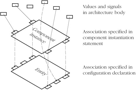
Figure 13.1. The generic and port maps in the component instantiation and the configuration declaration define a two-stage association. Values and signals in the architecture body are associated, via the local generics and ports, with the formal generics and ports of the bound entity.
Figure 13.1 shows that the actual values and signals supplied in the configuration declaration may be local generics or ports from the component instance. This is the case for the formal generics Tpd_01 and Tpd_10 and for the formal ports s0, s1, y0, y1, y2 and y3 in Example 13.8. Every local generic and port of the component instance must be associated with a formal generic or port, respectively; otherwise the design is in error. The figure also shows that the configuration declaration may supply values or signals from the architecture body. Furthermore, they may be any other values or signals visible at the point of the component instantiation statement, such as the literals ‘0’ and ‘1’ shown in the example. Note that while it is legal to associate a signal in the architecture body with a formal port of the entity, it is not good practice to do so. This effectively modifies the structure of the circuit, making the overall design much more difficult to understand and manage. For example, in the configuration in Example 13.8, had we associated the formal port s2 with the signal addr(6) instead of the literal value ‘0’, the operation of the circuit would be substantially altered. Note also that the two-level mapping of generics applies not only to generic constants, but also to generic types, subprograms, and packages.
The preceding examples show how we can use generic and port maps in binding indications to deal with differences between the component and the entity in the number and names of generics and ports. However, if the component and entity have similar interfaces, we can rely on a default binding rule. This rule is used automatically if we omit the generic map or the port map in a binding indication, as we did in the earlier examples in this section. The default rule causes each local generic or port of the component to be associated with a formal generic or port of the same name in the entity interface. If the entity interface includes further formal generics or ports, they remain open. If the entity does not include a formal with the same name as one of the locals, the design is in error. So, for example, if we declare a component as
   component nand3 is
     port ( a, b, c : in bit := '1';  y : out bit );
   end component nand3;
and instantiate it as
   gate1 : component nand3
     port map ( a => s1, b => s2, c => open, y => s3 );
then attempt to bind to an entity declared as
   entity nand2 is
     port ( a, b : in bit := '1';  y : out bit );
   end entity nand2;
with a component configuration
   for gate1 : nand3
     use entity work.nand2(basic);
   end for;
an error occurs. The reason for the error is that there is no formal port named c to associate with the local port of that name. The default rule requires that such a correspondence be found, even though the local port is unconnected in the architecture body.
We have seen that we can specify the binding for a component instance either by naming an entity and a corresponding architecture body, or by naming a configuration. A third option is to leave the component instance unbound and to defer binding it until later in the design cycle. The syntax rule for a binding indication that expresses this option is
binding_indication ⇐ use openIf we use this form of binding indication to leave a component instance unbound, we cannot include a generic map or port map. This makes sense: since there is no entity, there are no formal generics or ports with which to associate actual values or signals.
A scenario in which we may wish to defer binding arises in complex designs that can be partially simulated before all subsystems are complete. We can write an architecture body for the system, including component declarations and instances as placeholders for the subsystems. Initially, we write a configuration declaration that defers bindings of the subsystems. Then, as the design of each subsystem is completed, the corresponding component configuration is updated to bind to the new entity. At intermediate stages it may be possible to simulate the system with some of the components unbound. The effect of the deferred bindings is simply to leave the corresponding ports unassociated when the design is elaborated. Thus the inputs to the unbound modules are not used, and the outputs remain undriven.
Example 13.9. Deferred binding in a computer system model
Following is an outline of a structural architecture for a single-board computer system. The design includes all of the components needed to construct the system, including a CPU, main memory and a serial interface.
   architecture structural of single_board_computer is
     ...  -- type and signal declarations
     component processor is
       port ( clk : in bit;  a_d : inout word; ... );
     end component processor;
     component memory is
       port ( addr : in bit_vector(25 downto 0); ... );
     end component memory;

     component serial_interface is
       port ( clk : in bit;
              address : in bit_vector(3 downto 0); ... );
     end component serial_interface;
   begin
     cpu : component processor
       port map ( clk => sys_clk, a_d => cpu_a_d, ... );
     main_memory : component memory
       port map ( addr => latched_addr(25 downto 0), ... );
     serial_interface_a : component serial_interface
       port map ( clk => sys_clk,
                  address => latched_addr(3 downto 0), ... );
     ...
   end architecture structural;
However, if we have not yet designed an entity and architecture body for the serial interface, we cannot bind the component instance for the interface. Instead, we must leave it unbound, as shown in the following configuration declaration:
   library chips;
   configuration intermediate of single_board_computer is
     for structural
       for cpu : processor
         use entity chips.XYZ3000_cpu(full_function)
         port map ( clock => clk, addr_data => a_d, ... );
       end for;
       for main_memory : memory
         use entity work.memory_array(behavioral);
       end for;
       for all : serial_interface
         use open;
       end for;
       ...
     end for;
   end configuration intermediate;
We can proceed to simulate the design, using the implementations of the CPU and main memory, provided we do not try to exercise the serial interface. If the processor were to try to access registers in the serial interface, it would get no response. Since there is no entity bound to the component instance representing the interface, there is nothing to drive the data or other signals connected to the instance.
We complete this chapter with a discussion of configuration specifications. These provide a way of including binding information for component instances in the same architecture body as the instances themselves, as opposed to separating the information out into a configuration declaration. In some respects, this language feature is a relic of VHDL-87, which did not allow direct instantiation of entities in an architecture body. In VHDL-93 and VHDL-2002, if we know the interface of the entity and want to use it “as is,” we can instantiate it directly, without having to write a corresponding component declaration. The main remaining use of configuration specifications is to bind a known entity to component instances in cases where our idealized module is different from the entity. Using a component declaration to describe the idealized module may make the design easier to understand. The syntax rule for a configuration specification is
   configuration_specification ⇐
       for component_specification
           binding_indication ;
       [ end for ; ]
A configuration specification is similar to a component configuration, so we need to take care not to confuse the two. The component specification and binding indication are written in exactly the same way in both cases. However, a configuration specification does not provide an opportunity to configure the internal structure of the architecture to which the component instance is bound. That must be done in a separate configuration declaration. If we write a configuration specification for a component instance, it must be included in the declarative part of the architecture body or block that directly contains the component instance.
The effect of a configuration specification in an architecture body is exactly the same as if the binding indication had been included in a configuration declaration. Thus, we can bind a component instance to a design entity, and we can specify the mapping between the local generics and ports of the component instance and the formal generics and ports of the entity.
Example 13.10. A configuration specification binding a gate component
Suppose we need to include a two-input nand gate in a model, but our library only provides a three-input nand gate, declared as
   entity nand3 is
     port ( a, b, c : in bit;  y : out bit );
   end entity nand3;
We can write our model using a component declaration to show that we really would prefer a two-input gate, and include a configuration specification to handle the difference in interfaces between the component instance and the entity. The architecture is
   library gate_lib;
   architecture ideal of logic_block is
     component nand2 is
       port ( in1, in2 : in bit;  result : out bit );
     end component nand2;
     for all : nand2
       use entity gate_lib.nand3(behavioral)
       port map ( a => in1, b => in2, c => '1', y => result );
     end for;
     ...  -- other declarations
   begin
     gate1 : component nand2
       port map ( in1 => s1, in2 => s2, result => s3 );
     ...  -- other concurrent statements
   end architecture ideal;
VHDL-87, -93, and -2002
In these versions of VHDL, the reserved words end for cannot be included in a configuration specification. For example, the configuration specification in Example 13.10 must be written as
   for all : nand2
     use entity gate_lib.nand3(behavioral)
     port map ( a => in1, b => in2, c => '1', y => result );
We have now seen that there are two places where we can specify the mapping between the local generics and ports of a component instance and the formal generics and ports of the bound entity. The mappings can be specified either in a configuration specification or in a separate configuration declaration. We must now consider the possibility of having two binding indications for a given component instance, one in each of these places. VHDL does, in fact, allow this. The first binding indication, in the configuration specification in the architecture body, is called the primary binding indication. The second binding indication, in the configuration declaration, is called an incremental binding indication. The primary binding indication must at least specify the entity or configuration to which the instance is bound and may also include generic and port maps. If there is a primary binding indication, the incremental binding indication can either repeat the entity part exactly as specified in the primary binding indication, or it can omit the entity part. The full syntax rule for a binding indication allows for the entity part to be omitted in this case (see Appendix B). The incremental binding indication can also include generic and port maps, and the associations in them override those made in the primary binding indication, with some restrictions. An incremental binding indication must include at least one of the entity part, a port map or a generic map, since it must not be empty. Further, the only generics that can be incrementally bound are generic constants, not generic types, subprograms, or packages. We look at the various possibilities for incremental binding, with some examples.
The first possibility is that the primary binding indication for a component instance leaves some of the formal generic constants or ports of the entity unassociated. In this case, the incremental binding indication can “fill in the gaps” by associating actual values and with the unassociated generic constants and ports.
Example 13.11. Incremental binding of unassociated generic constants and ports
Following is an architecture body for the control section of a processor, including a register component to store flag bits.
   architecture structural of control_section is
     component reg is
       generic ( width : positive );
       port ( clk : in std_ulogic;
              d : in std_ulogic_vector(0 to width - 1);
              q : out std_ulogic_vector(0 to width - 1) );
     end component reg;
     for flag_reg : reg
       use entity work.reg(gate_level)
       port map ( clock => clk, data_in => d, data_out => q );
     end for;
     ...
   begin
     flag_reg : component reg
       generic map ( width => 3 )
       port map ( clk => clock_phase1,
                  d(0) => zero_result, d(1) => neg_result,
                  d(2) => overflow_result,
                  q(0) => zero_flag, q(1) => neg_flag,
                  q(2) => overflow_flag );
     ...
   end architecture structural;
The configuration specification binds the register component instance to the following register entity:
   library ieee;  use ieee.std_logic_1164.all;
   entity reg is
     generic ( t_setup, t_hold, t_pd : delay_length;
               width : positive );
     port ( clock : in std_ulogic;
            reset_n : in std_ulogic := 'H';
            data_in : in std_ulogic_vector(0 to width - 1);
            data_out : out std_ulogic_vector(0 to width - 1) );
   end entity reg;
This entity has additional formal generic constants t_setup, t_hold and t_pd for timing parameters, and an additional port, reset_n. Since the component declaration does not include corresponding local generic constants and ports, and the configuration specification does not specify values or signals for the formal generic constants and ports, they are left open in the architecture body.
The configuration declaration for the design, shown below, contains an incremental binding indication for the register component instance. It does not specify an entity/architecture pair, since that was specified in the primary binding indication. It does, however, include a generic map, filling in values for the formal generic constants that were left open by the primary binding indication. The generic map also associates the value of the local generic constant width with the formal generic constant width. The port map in the incremental binding indication associates the literal value ‘1’ with the formal port reset_n.
   configuration controller_with_timing of control_section is
     for structural
       for flag_reg : reg
         generic map ( t_setup => 200 ps, t_hold => 150 ps,
                       t_pd => 150 ps, width => width )
         port map ( reset_n => '1' );
       end for;
       ...
     end for;
   end configuration controller_with_timing;
The second possibility is that the primary binding indication associates actual values with the formal generic constants of the entity bound to the component instance. In this case, the incremental binding indication can include new associations for these formal generic constants, overriding the associations in the primary binding indication. This may be useful in the back-annotation stage of design processing. Estimates for values of generic constants controlling propagation delay can be included in the primary binding indication and the design simulated before doing physical layout. Later, when actual delay values have been calculated from the physical layout, they can be included in incremental binding indications in a configuration declaration without having to modify the architecture body in any way.
Example 13.12. Incremental rebinding of generic constants
The following outline of an architecture body for the interlock control logic of a pipelined processor declares a nor-gate component with a generic constant for the input port width, but with no generic constants for timing parameters.
   architecture detailed_timing of interlock_control is
     component nor_gate is
       generic ( input_width : positive );
       port ( input : in std_ulogic_vector(0 to input_width - 1);
              output : out std_ulogic );
     end component nor_gate;
     for ex_interlock_gate : nor_gate
       use entity cell_lib.nor_gate(primitive)
       generic map ( width => input_width,
                     Tpd01 => 250 ps, Tpd10 => 200 ps );  -- estimates
     end for;
     ...
   begin
     ex_interlock_gate : component nor_gate
       generic map ( input_width => 2 )
       port map ( input(0) => reg_access_hazard,
                  input(1) => load_hazard,
                  output => stall_ex_n);
     ...
   end architecture detailed_timing;
The architecture includes a configuration specification for the instance of the gate component, which binds it to a nor-gate entity that does include generic constants for timing. The generic map in the configuration specification supplies estimates of the timing as actual values for the generic constants.
This model can be simulated with these estimates by configuring it as follows:
   configuration interlock_control_with_estimates
     of interlock_control is
     for detailed_timing
     end for;
     ...
   end configuration interlock_control_with_estimates;
Since there is no further configuration information supplied for the nor-gate instance, the estimated timing values are used. After the design has been laid out and the real timing values have been determined, the configuration declaration can be updated as follows:
   configuration interlock_control_with_actual
     of interlock_control is
     for detailed_timing
       for ex_interlock_gate : nor_gate
         generic map ( Tpd01 => 320 ps, Tpd10 => 230 ps );
       end for;
       ...
     end for;
   end configuration interlock_control_with_actual;
An incremental binding indication has been added, supplying the new values for the generic constants. When the design is simulated with this updated configuration, these new values override the estimates specified in the primary binding indication in the architecture body.
The third possibility to consider is that the primary binding indication associates actual signals with the formal ports of the entity. In this case, the incremental binding indication cannot override the associations, since to do so would modify the structure of the design.
The final case that arises is one in which a component instantiation associates actual values and signals with local generic constants and ports, but the primary binding indication does not explicitly associate actual values or signals with formal generic constants or ports of the same name. In this case, the default binding rule normally causes the local generic constants to be associated with formal generic constants of the same name and local ports to be associated with formal ports of the same name. However, we can preempt this default rule by supplying alternative associations for the formal generic constants and ports in the incremental binding indication.
Example 13.13. Incremental binding in place of default association
Following is an outline of an architecture body for a block of miscellaneous logic. It includes a component declaration for a three-input nand gate and an instance of the component with an actual value supplied for a local timing generic. The primary binding indication binds the instance to a three-input nand gate entity, but does not specify the mappings between the local generic and ports and the formal generic and ports.
   architecture gate_level of misc_logic is
     component nand3 is
       generic ( Tpd : delay_length );
       port ( a, b, c : in bit;  y : out bit );
     end component nand3;
     for all : nand3
       use entity project_lib.nand3(basic);
     end for;
     ...
   begin
     gate1 : component nand3
       generic map ( Tpd => 2 ns )
       port map ( a => sig1, b => sig2, c => sig3, y => out_sig );
     ...
   end architecture gate_level;
The configuration declaration for this design shown below overrides the default mapping. It supplies an actual value for the formal timing generic Tpd, instead of using the value of the local generic of that name. It maps the local port c onto the formal port a, and the local port a onto the formal port c. The local ports b and y map onto the formal ports of the same names.
   configuration misc_logic_reconfigured of misc_logic is
     for gate_level
       for gate1 : nand3
         generic map ( Tpd => 1.6 ns )
         port map ( a => c, c => a, b => b, y => y );
       end for;
     end for;
   end configuration misc_logic_reconfigured;
VHDL-87
VHDL-87 does not allow incremental binding. It is an error if a design includes both a configuration specification and a component configuration for a given component instance. If we expect to revise the associations in a generic map or port map of a configuration specification, we should omit the configuration specification and write the initial associations in the configuration declaration. Later, when we need to revise the associations, we can simply edit the configuration declaration without changing the architecture containing the component instance.
[ | |||||||||||||
[ | |||||||||||||
[ | |||||||||||||
[ | |||||||||||||
[ architecture register_transfer of digital_filter is ... component multiplier is port ( ... ); end component multiplier; begin coeff_1_multiplier : component multiplier port map ( ... ); ... end architecture register_transfer; Write a configuration declaration that binds the multiplier component instance to a multiplier entity called | |||||||||||||
[ | |||||||||||||
[ | |||||||||||||
[ component multiplexer is port ( s, d0, d1 : in bit; z : out bit ); end component multiplexer; ... serial_data_mux : component multiplexer port map ( s => serial_source_select, d0 => rx_data_0, d1 => rx_data_1, z => internal_rx_data ); Write a binding indication that binds the component instance to the following entity in the current working library, using the most recently analyzed architecture and specifying a value of 3.5 ns for the propagation delay. entity multiplexer is generic ( Tpd : delay_length := 3 ns ); port ( s, d0, d1 : in bit; z : out bit ); end entity multiplexer; | |||||||||||||
[ | |||||||||||||
[ entity nand4 is generic ( Tpd_01, Tpd_10 : delay_length := 2 ns ); port ( a, b, c, d : in bit := '1'; y : out bit ); end entity nand4; We bind the entity to the component instance for gate1 : nand3 use entity get_lib.nand4(basic); end for; Write the generic and port maps that comprise the default binding indication used in this configuration. | |||||||||||||
[ | |||||||||||||
[ | |||||||||||||
13. | [ | ||||||||||||
14. | [ | ||||||||||||
15. | [ | ||||||||||||
16. | [ | ||||||||||||
17. | [ | ||||||||||||
18. | [ entity XYZ1234A is generic ( T_phi_out, T_d_z : delay_length; debug_trace : boolean := false ); port ( phi1, phi2 : in std_ulogic; -- 2 phase clock cs : in std_ulogic; -- chip select a : in std_ulogic_vector(1 downto 0); -- address d : inout std_ulogic_vector(1 downto 0); -- data int_req : out std_ulogic; -- interrupt rx_d : in std_ulogic; -- rx serial data tx_d : out std_ulogic ); -- tx serial data end entity XYZ1234A; Write a configuration declaration that binds the | ||||||||||||
19. | [ S = (A ⊕ B) ⊕Cin Cout = A ⋅ B + (A ⊕ B) ⋅ Cin Write behavioral models of entities corresponding to each of the gate components and a configuration declaration that binds each component instance in the full adder to the appropriate gate entity. | ||||||||||||
20. | [ | ||||||||||||
21. | [ | ||||||||||||
22. | [ M(a,b,c) = a ⋅ b ⋅ c + a ⋅ b ⋅ c ¯ + a ⋅ b ¯ ⋅ c + a ¯ ⋅ b ⋅ c Develop a structural model of a three-input majority circuit, using inverter, and-gate and or-gate components with standard-logic inputs and outputs. Also develop behavioral models for the inverter and gates, including generic constants in the interfaces to specify propagation delays for rising and falling output transitions. Include configuration specifications in the structural model to bind the component instances to the entities. The configuration specifications should include estimated propagation delays of 2 ns for all gates. Next, develop a configuration declaration for the majority circuit that includes incremental bindings to override the estimated delays with actual propagation delays as shown below.
| ||||||||||||
23. | [
The stopwatch counter is initially reset to 00’00”00, with the display showing the counter time and the minute and second indicators on. In this state, pressing the start/stop button starts counting, with the display showing the counter time. Pressing the start/stop button again stops counting. Successive presses of start/stop continue or stop counting, with the display showing the counter time. If the lap/reset button is pressed while the counter is stopped and the display is showing the counter time, the counter is reset to 00’?00” 00. If the lap/reset button is pressed while the counter is running, the display freezes the time at which the lap/reset button was pressed, the counter continues running and the minutes and seconds indicators flash at a 1 Hz rate to indicate that the counter is still running. If the start/stop button is pressed, the counter stops, the minutes and seconds indicators stop flashing and the displayed time is unchanged. Successive presses of start/stop continue or stop counting, with the displayed time unchanged and the minutes and seconds indicators flashing when the counter is running. Pressing the lap/reset button while the display is frozen causes it to return to displaying the current counter time, whether the counter is running or stopped. The first model in your suite should be a behavioral model. Test your behavioral model by writing a test bench for it. You should write a configuration declaration for the test bench that binds the unit under test to the behavioral stopwatch model. Next, refine your stopwatch model to a structural design, including a control sequencer, registers, counters, decoders and other components as required. Develop behavioral models corresponding to each of these components, and write a configuration for the stopwatch that binds the behavioral models to the component instances. Revise the test bench configuration to use the structural model, and compare its operation with that of the behavioral model. Continue this process of refinement by implementing the control sequencer as a finite-state machine with next-state logic and a state register and by implementing the other components using successively lower-level components down to the level of flipflops and gates. At each stage, develop configuration declarations to bind entities to component instances, and test the complete model using the test bench. |