In Chapter 4, we looked at the functionality that SIP (Session Initiation Protocol) provides from the end user’s point of view. In Chapter 6, we learned a bit more about the network perspective: SIP messages and how they are exchanged between the SIP entities. In this chapter, we take a closer look into the internals of the protocol itself, how its functionality is internally organized and achieved. From that perspective, we will see a model that splits the protocol functionality into several layers. The interest of this approach, apart from giving us a deeper insight into the way SIP works, lies in the fact that many SIP software implementations use a similar layered approach in order to implement the SIP functions. Most specifically, that is the case of the JAIN SIP API (Application Programming Interface), which we will be looking at in the next chapter. So a good understanding, especially of the transaction layer, is crucial to fully understand how JAIN SIP applications work. Last, we will look into the SIP dialog concept. The SIP dialog is a crucial concept for building User Agents (UAs)and advanced SIP applications on top of UAs or Back-to-Back User Agents (B2BUAs).
[RFC 3261] structures the SIP functionality in several layers. This means that SIP protocol behavior is described, in this specification, as a set of fairly independent processing stages with only a loose coupling between each stage. These processing stages can be seen as layers that obtain services from the layer below and provide services to the layer above. This is very much in the same way as different protocol layers in the TCP/IP suite also communicate to each other in order to achieve the complete functionality for end users. This layered approach for SIP in [RFC 3261] does not dictate how SIP implementations should be made; however, many SIP implementations follow this model to some extent, and offer APIs for some of the layers. That is the case of the JSIP API, which offers mainly an interface for a SIP transaction layer. We will start using the JSIP interface in the next chapter once the concepts in this chapter are clearly understood.
Because the layers described in this section are internal layers within SIP, which is itself sitting at the application layer in the TCP/IP model, I will refer to them as sublayers. I think this helps to better understand where SIP stands in the context of the TCP/IP suite, and also avoids confusions between the SIP transport layer (called “SIP transport sublayer” in this book) and the TCP/IP transport layer (called simply “transport layer” in this book). As we will see, the SIP transport sublayer is a layer within SIP, and therefore pertains to the application layer, whereas the transport layer (e.g., UDP, TCP) is a full TCP/IP layer on its own. These two layers are contiguous layers, and therefore need to communicate to each other.
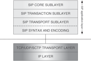
Next is a top-down list of the SIP sublayers. Higher layers are closer to the actual SIP application and the end-user view, whereas lower layers are closer to the next layer down in the TCP/IP protocol suite.
SIP core sublayer: This is the sublayer where the service logic specific to each SIP entity is implemented. It may have five different components, called cores, corresponding to the different SIP entities: UAC (User Agent Client), UAS (User Agent Server), registrar, stateful proxy, and stateless proxy.
SIP transaction sublayer: This is the sublayer where the transaction processing is implemented. It contains a service logic that is common to many SIP entities. It comprises two components: a client side called client transaction, and a server side called server transaction.
SIP transport sublayer: This is the sublayer responsible for actual transmission and reception of the SIP messages. It has two components: a client side called client transport, and a server side called server transport.
SIP syntax and encoding function: Rather than a sublayer, this represents a function that needs to be invoked in order to encode/decode the SIP messages when they are sent/received through the TCP/IP socket interface.[1] For the purpose of the following discussion, we will consider this function to be a part of the SIP transport sublayer.
Figure 7.1 shows the SIP layer, with its sublayers, in the context of the rest of the TCP/IP protocol suite.
In order for the reader to realize how the different sublayers are used by the different SIP entities, in this section we depict the internal sublayers within each of the SIP entities.
A SIP UA (Figure 7.2) implements the UAC-core, UAS-core, transaction, and transport sublayers.
A registrar (Figure 7.3) implements the registrar-core, transaction, and transport sublayers.
A stateful proxy (Figure 7.4) implements the stateful-proxy-core, transaction, and transport sublayers. Proxies will be studied in Chapter 13.
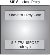
A stateless proxy (Figure 7.5) implements the stateless-proxy-core and transport sublayers. It has no transaction sublayer. Proxies will be studied in Chapter 13.
Now that the SIP protocol layers have been outlined, we will now look a bit more in detail into each of them.
This is the highest layer. It is the layer where the specific functionalities of SIP entities are implemented. Different SIP entities have different service logics in this layer, although they might share the logic in the other layers. These service logics are called SIP cores. So, all the SIP entities contain a core that distinguishes them from each other. The SIP core sublayer contains a number of SIP cores, one for each SIP entity: UAC, UAS, stateless proxy, stateful proxy, and registrar. Actually, a registrar is a type of UAS, but, given its relevance, it is given a special name and considered as a separate core. It is important to bear in mind that these SIP entities are logical elements, not physical ones. A physical implementation might act as different SIP entities. Usually SIP registrars and proxies are bundled together in the same box, typically referred to as a SIP server.
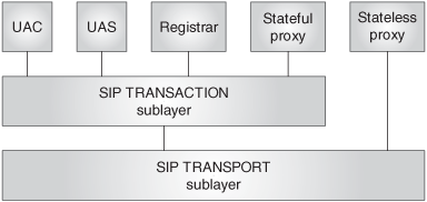
The SIP cores implemented in this layer can be split into two types: transaction users and transport users.
A SIP core is said to be a transaction user if it makes use of the transaction sublayer below. In order to send a request, a transaction user creates a client transaction instance in the transaction sublayer below, and passes to it the request, along with the destination IP address, port, and transport to which to send the request. Likewise, incoming responses are received from the same client transaction instance.
The following cores are transaction users: UAC core, UAS core, stateful-proxy core, registrar core.
A transport user is said to be an entity that uses the SIP transport sublayer. In that sense, the transaction sublayer is a transport user. There is only one SIP core that is not a transaction user but a transport user, meaning that it directly communicates with the transport sublayer, bypassing the transaction sublayer, in order to implement its functionality. Such a core is the stateless-proxy core. Proxies, both stateless and stateful, will be examined in Chapter 13.
Figure 7.6 shows the transport users and the transaction users and their relationship with the rest of the SIP sublayer components.
SIP, as an application-layer protocol, makes use of transport-layer protocols such as UDP or TCP to send and receive requests and responses. We saw in Chapter 3 that TCP provides a reliable transport service. Therefore, when SIP uses TCP as the transport, it knows that the messages will be reliably delivered to the destination. On the other hand, SIP can also use UDP as a transport, and this protocol does not offer a reliable message-delivery service. Therefore, SIP, when forwarding a message to the UDP layer for transmission, does not have the guarantee that the message will reach the destination. In order to cope with this limitation when using UDP, SIP implements, as part of the application layer, a service logic that guarantees reliable delivery of messages. This logic basically utilizes retransmissions of messages upon expiration of timers in order to guarantee reliability in message delivery. This piece of service logic resides mainly in the transaction sublayer. Actually, this is its main function, though this layer also offers other functions, as we will see in the next sections. The transaction sublayer is utilized by the transaction user irrespective of the used network transport protocol (TCP/UDP/SCTP [Stream Control Transmission Protocol]), but its full functionality is exploited mainly when SIP uses UDP.
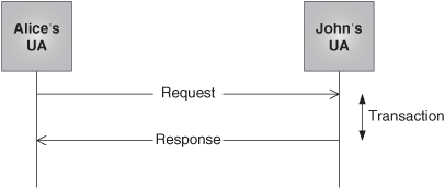
The mechanism that is used in order to implement this reliability at the application layer revolves around the transaction concept. As we said in the previous chapter, any SIP message is either a request or a response. A SIP transaction consists of a single request and any response to that request, which include zero or more provisional responses and one or more final responses. The transaction sublayer assures reliable message delivery within each transaction. It contains the logic needed to handle transactions and retransmit messages. Figure 7.7 shows a SIP transaction composed of a request and the corresponding response.
The transaction sublayer is located between the transaction user and the SIP transport sublayer. On one hand, it receives messages from the transaction user and passes them to the SIP transport layer for transmission in the network. On the other hand, it receives messages from the transport layer (coming from the network) and passes them to the transaction user. This is depicted in Figure 7.8.
Transactions have a client side and a server side. The client side is known as a client transaction, and the server side as a server transaction. The client transaction sends the requests and receives the responses, whereas the server transaction receives the requests and sends back the responses.
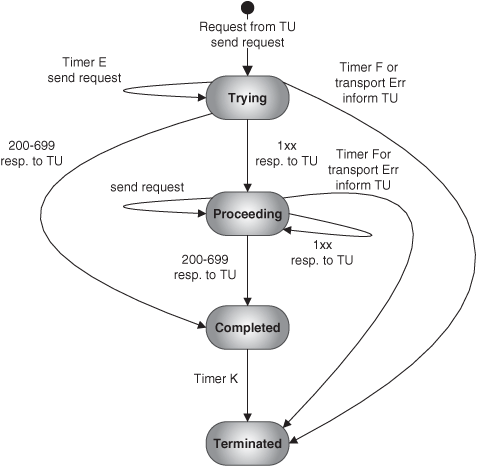
Client and server transactions provide their functionality through the maintenance of a state machine. The state machines are different depending on the type of transaction: INVITE or non-INVITE transaction. The state machines for the client transactions in the different cases are shown in Figures 7.9, 7.10. The state machines for the server transactions are shown in Figures 7.11, and 7.12. These are included for information, but will not be explained in detail in this book. Readers are referred to RFC 3261 for a detailed explanation of the state machines.
The client and server transactions are logical functions that are embedded in any number of elements. Specifically, they exist within User Agents and stateful-proxy servers.
The transaction layer is not a mere relay of messages between software layers. It offers two main services to the transaction user.
The first one is the correlation of messages pertaining to the same transaction. This is particularly useful for SIP entities, such as proxies, that need to handle a lot of transactions simultaneously, and therefore need to know to which transaction a particular incoming message corresponds in order to apply the proper service logic. A response belongs to the same transaction as a request if the two following conditions are met:
Both request and response have the same value as the “branch” parameter in the top Via header field.
Both request and response have the same value as the “method” parameter in the Cseq header field.[2]
The second function, as was already mentioned, is the reliable transmission of SIP messages within the transaction. This aspect is particularly useful when using nonreliable transports such as UDP. In such cases, the transaction layer implements the retransmission mechanisms necessary to assure reliable delivery. The transaction layer also filters out the retransmission in the receiving end so that the SIP core layer is not bothered by them. All in all, the transaction layer frees the transaction user from the need of implementing the necessary mechanisms in order to guarantee reliable delivery of messages in those cases where a nonreliable transport protocol, such as UDP, is used.
The transaction sublayer provides reliability in a hop-by-hop fashion—that is, between peer-transaction sublayer elements. In case the signaling transmission path goes through various proxies, transactions provide reliability in each hop, not in an end-to-end way. This is shown in Figure 7.13.
The way reliable delivery is implemented by the transaction sublayer depends on the type of transaction. We consider the split between non-INVITE transactions and INVITE transactions.
Non-INVITE transactions implement a two-way handshake. For unreliable transports, requests are retransmitted by the client transaction at specified intervals. On the other hand, the server transaction will retransmit responses if a new request arrives. Once a final response has been sent by the server transaction, it will still wait for some time (timer J) to see if it receives a new retransmission of the request, which would indicate that the response was not transmitted successfully. After timer J expires, the server transaction is terminated. This behavior is reflected in the transaction-state machines shown in Figures 7.9 and 7.11.
In Figure 7.14, a generic non-INVITE transaction between Alice and John is shown. We assume that the transport is UDP and that some messages are lost, so that we can see the retransmissions in action.
Non-INVITE transactions are expected to complete rapidly. For instance, when a REGISTER request reaches a registrar, the registrar will populate the Location Service and immediately send a response. On the other hand, when Alice sends an INVITE request to John, he needs to press a button in order to accept Alice’s incoming call, and that might take some time. INVITE transactions normally require human input to complete, and therefore they typically have an extended duration. The long delays expected for sending a response argue for a three-way handshake, as opposed to the two-way handshake in non-INVITE transactions. In the next paragraphs, we explain the reason for this.
As soon as a request is sent, the client transaction will retransmit the request at specified intervals until a provisional response is received (provisional responses do not normally need human input to be generated). At that point, retransmissions are stopped; there is no point in continuing with the retransmissions because the UAC is just waiting for the UAS to accept the call, which may take some time. This is as opposed to what happens in non-INVITE transactions, where the client transaction does not stop sending retransmissions until a final response is received.
So, if the client transaction for the INVITE requests stops sending retransmissions after the first provisional response is received, how can the server transaction be sure, after sending back a final response, that the response has been received by the client transaction? In order to solve this issue, the INVITE transaction departs slightly from the simple request/response model and introduces a three-way handshake. In this model, after receiving a final response, the client transaction should send an ACK message so that the server transaction can be sure that the final response was successfully delivered. After sending the final response, the server transaction will retransmit it at the occurrence of either of these two events: a new INVITE is received, or a timer, called timer G, expires. Once a final response has been sent by the server transaction, it will still wait for some time (timer H) to receive the ACK. If timer H fires, it implies that no ACK was received, and thus the server transaction is terminated and an error condition reported to the transaction user.
This way of dealing with final responses and ACK messages is, though, applied only for final responses with status codes from 300 to 699—that is, in failure scenarios. Why is this so, and what happens with the 2xx responses? In order to answer this question, we have to remember that the transaction layer offers reliable delivery only in a hop-by-hop approach. What this means is that a transaction-aware SIP entity assures that messages are received by the next transaction-aware SIP entity. It is the next transaction-aware entity (for instance, a SIP stateful proxy) that takes responsibility for delivering the message to the next entity. And this process is repeated in every hop until the message gets to the target UA. The 2xx responses are considered too important to use this hop-by-hop reliability mechanism. This type of response typically triggers additional procedures in the UA media layer, so it is crucial to have an end-to-end-reliability approach when handling them. What this means is that retransmission of 2xx messages and generation of ACK messages is considered a function of the SIP core layer, and not of the transaction sublayer. A corollary of all this is that the ACK message, when sent as a result of the reception of 2xx responses, is not part of the INVITE transaction, whereas if the received response had status code between 300 and 699, the subsequent ACK would be part of the INVITE transaction.
This behavior is reflected in the state machines for INVITE transactions shown in Figures 7.10 and 7.12.
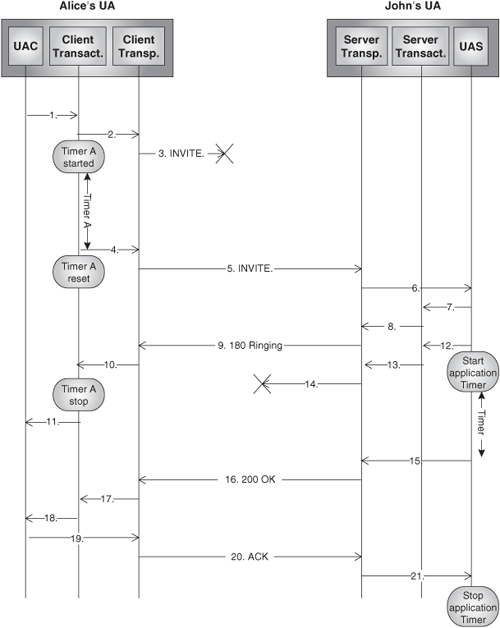
We will now look at a practical example in order to illustrate the behavior of client and server transactions. We will show the most complex case of an INVITE transaction—first in a direct scenario (without proxies), and then in the typical SIP trapezoid architecture. In the following examples, the transport protocol is considered to be UDP so as to highlight the transaction-layer functions related to providing reliability in the message exchange.
Let us assume that Alice wants to set up a voice call with John, and her UA is able to determine the IP address and port to use in order to set up the call directly to John. Figure 7.15 shows the example.
Alice will produce some input (i.e., press a button), and the UAC core will generate an INVITE, create a new client transaction, and pass the message to it.
The client transaction will pass the message to the SIP transport sublayer for transmission, and start Timer A.
The network happens to be congested at that moment, and so an IP router in the path discards the UDP datagram.
Timer A expires, and the client transaction passes the INVITE request again to the client transport. The client transaction resets timer A.
The client transport sends the request, and, in this case, the INVITE reaches John’s UA.
The SIP transport sublayer receives the request and passes it to the UAS core.
The UAS core creates a new server transaction, alerts John by locally generating a ringing tone, creates a 180 provisional response, and forwards the response to the recently created server transaction.
The server transaction passes the response to the transport sublayer for transmission.
The 180 Ringing response reaches Alice’s UA.
The transport sublayer passes the message to the appropriate client transaction.
The client transaction stops timer A and passes the message to the UAC core. The UAC core generates a local ringing tone to let Alice know that John is being alerted.
John accepts the call. The UAS core generates a 200 OK response, starts a timer, and passes the message to the server transaction.[3]
The server transaction passes the response to the transport sublayer and is automatically terminated.
The transport sublayer transmits the response, but a new congestion situation in a router in the path cause the message to be dropped.
The timer in step 12 fires, and causes the UAS core to pass the message again for transmission, this time directly to the transport sublayer because the transaction is now terminated.
The 200 OK is now received by the transport layer in Alice’s UA.
The transport layer in Alice’s UA passes the 200 OK response to the client transaction.
The client transaction forwards the message to the UAC core and is destroyed.
The UAC core will generate an ACK request and pass it directly to the transport sublayer for transmission.
ACK message reaches the transport sublayer in John’s UA.
The message is passed to the UAS core, which stops the timer.
In this case, for simplicity reasons, we will not show the SIP transport sublayers. Figure 7.16 shows the call flow.
The SIP transport sublayer is responsible for the actual transmission/reception of requests and responses over/from network transports. So, the SIP transport sublayer:
Determines the transport connection over which requests and responses need to be sent or received.
Instructs the transport layer to create transport connections.
Instructs the transport layer to listen for incoming messages.
Instructs the transport layer to send or receive SIP messages.
Forwards received responses from the transport layer to the appropriate transport user (either a client transaction or the UA core).
Is responsible for framing SIP messages.
Handles transport-layer errors.
The network transport-layer functionality is normally exposed by the socket API implemented by the operating system. In those cases, it would be the SIP transport sublayer, the one responsible for managing the socket API (creating sockets, sending and receiving data through them, and so on). Any upper layer that uses the SIP transport sublayer is called the transport user.
The SIP transport sublayer is split into client transport and server transport. Let us look more in detail at the functions of each.
The client transport is responsible for receiving requests from the transport user and transmitting them over the network. It is also responsible for receiving responses from the network and forwarding them to the appropriate transport user.
The user of the transport layer passes to the client transport the request, an IP address, port, and transport. Before the request is sent, the client transport inserts an address (IP address, port) into the “sent-by” field in the Via header. This address is used to help the server route responses back to the client (see the section “Sending Responses”), and typically corresponds to the IP address of the host where the client transaction is located, and to the port used as source port for sending the request. If the port is absent, the default value depends on the transport. It is 5060 for UDP, TCP, and SCTP; 5061 for TLS (Transport Layer Security).[4]
The behavior of the client transaction depends on the value of the transport passed by the transport user.
If the requested transport is reliable (TCP or SCTP), and the request is destined to an IP address, port, and transport to which an existing connection is open, the client transport would use that connection to send the request. If there is no match, the client would create a new connection and send the request over the new connection. The client transport must be prepared to receive the responses to the request over the used connection. In addition, the client must also be prepared to receive incoming connections on the port contained in the Via header.
If the requested transport is not reliable (UDP), then the client transport will directly send the message to the indicated address. The client transport must be prepared to receive responses on the port contained in the Via header.
When receiving a response, the client transport will try to match it to an existing client transaction. If there is a match, the client transport passes the response to the appropriate client transaction. If there is no match, the client transport passes the response directly to the SIP core.
The server transport is responsible for receiving requests from the network and forwarding them to the transport user.
A transport server is typically listening on port 5060 for UDP, TCP, and SCTP (5061 for TLS), or any other port on which it knows that requests may be received. When the transport server receives a request, it will check what is the real IP address from which the request was received. If that address is different from the one contained in the “sent-by” field of the Via header, then the server transport will add a “received” parameter into the Via header, set to the value of the originator’s IP address.
Next, the server transport will pass the request to a server transaction (if the request can be matched to an existing server transaction) or to the SIP core.
The way to send the response depends on what transport was used in the request.
If the request was sent over a reliable transport protocol, such as TCP or SCTP, the response must be sent on the existing connection over which the request was received. If such a connection does not exist anymore, a new connection should be opened to the IP address in the “received” parameter and the port in the Via header.
If the request was sent over UDP, the response will be sent to the IP address in the “received” parameter and the port in the Via header. If no “received” parameter exists, the response will use the IP address in the “sent-by” field of the Via header instead.
In order to illustrate some of the concepts related to the behavior of the SIP transport sublayer, let us look at how a simple registration procedure would work from the transport perspective.
Let us assume that John receives SIP services from a SIP provider called “Sea.” This provider offers a registrar service identified by the following SIP URI (Universal Resource Identifier):
sip: registrar.sea.com
The provider also offers a DNS (Domain Name System) service that maps that URI into the actual address (1.1.1.1), port (5060), and transport (TCP) on which the registrar expects to receive requests.
The SIP provider communicates to John, as part of the subscription information, the SIP URI of the registrar and the IP addresses of the DNS service. John configures his User Agent with all this data.
When John starts up his UA, the UAC core component will look into the preconfigured SIP URI for the registrar, and will resolve it to an IP address, port, and transport—in this case: 1.1.1.1, 5060, and TCP. After that, the following steps will take place:
The UAC core builds a REGISTER request, creates a client transaction, and forwards the request to it, together with the IP address, port, and transport.
The client transaction receives the request, creates the necessary state, and executes its functions, after which it passes the request—together with the IP address, port, and transport—to the client transport.
Given that the requested transport is TCP, the client transport will check if there is an existing TCP connection that links with the requested IP address and port. Given that the UA was just started, we will assume that there exists no valid TCP connection, so the client transport will establish a new TCP connection to IP 1.1.1.1 and port 5060, and send the request over it. Before sending the message, the client transport adds its IP address into the Via header of the request.
The client transport will listen for responses to the request on the newly created connection.
The registrar is listening for new connections on port 5060. It accepts the new connection from John and receives the request on that connection. The server transport will check the Via header. Given that the IP address in the Via header corresponds to the same IP address from which the request was received, it does not add a “received” parameter.
The server transport finds no match for the request to an existing transaction, and therefore passes the request to the UAS core, which will create a new server transaction.
The UAC core will update the bindings in the Location Service, generate a successful 200 OK response, and pass it to the recently created server transaction.
The server transaction will execute its functions and pass the response to the server transport. The server transport will check that the request corresponding to the actual response was sent over a TCP connection, so it will send the response back to the UAC over the same TCP connection.[5]
The client transport will receive the response over the original connection, find a match for the corresponding client transaction, and pass the response to the client transaction.
The client transaction passes the response to the UAC core, which notifies John that the UA is now registered.
This function represents the actual encoding of the SIP messages for transmission on the wire. The data passed by the SIP transport sublayer to the socket API for transmission over the TCP/IP suite needs to comply with the SIP syntax and encoding rules.
Encoding rules for SIP are specified using Augmented Backus-Naur Form (ABNF) grammar [RFC 4234].
When a SIP UA sends an INVITE request to another UA, and the latter responds with a 200 OK response, a peer-to-peer relationship is created between the two UAs—a relationship that will persist for the duration of the call. This peer-to-peer relationship is called a SIP dialog, and it represents a context in which to interpret SIP messages. In [RFC 3261], the INVITE request is the only one that can create dialogs, but other methods defined in SIP extensions may also set up dialogs (e.g., the SUBSCRIBE method, which we will see in Chapter 15).
So, what is the use of dialogs?
First of all, UAs need to be able to ascertain what messages pertain to a particular dialog. Let us imagine that there are several dialogs established against the same UAS. At a certain point in time, the UAS core receives a BYE request to terminate one of those dialogs. In order to know what dialog needs to be terminated, the UAS needs to identify to which dialog the BYE request belongs.
Second, once a dialog has been established, new requests can be sent by any of the participating User Agents. In order to route these new mid-dialog requests, the UA uses some information that it stored during the dialog-initiation phase. This information context will be used to facilitate proper routing and sequencing of new messages generated within that dialog. Furthermore, this context information might vary during the dialog, and it is important to keep it updated.
Third, in some cases, there are end-user applications built on top of the UA core that may need to store states associated with each dialog. For instance, we might consider a voice-mail application built on top of a UAS. The users can set up a session toward this UAS. Once the session has been established, the users can interact with the application by dialing DTMF (Dual-Tone Multi-Frequency) in order to decide what actions they want to execute: listen to stored voice messages, delete messages, change the welcome message, and so on. Typically, Voice Mail Systems (VMSs) implement a call-flow logic that requires maintaining some state associated to each user so that the application can know in every moment where in the call flow a particular user is. In other words, the application needs to maintain the state associated with the dialog.
The three examples above highlight the need for UAs to be able to:
Unambiguously identify dialogs.
Store the state associated with each dialog, and use it to generate future in-dialog requests.
Dialogs are identified at each UA (local and remote) with a dialog ID. The dialog ID consists of a call-identifier value, a local tag, and a remote tag. The Call-ID is the same in both User Agents, and the local tag in a UA is identical to the remote tag in its peer. Figure 7.17 shows the parameters at each UA that make up the dialog ID.
Dialog identification is carried in the signaling, and so, by looking at the content of a SIP message, the UAS can learn to which dialog the message pertains. Let us see how.
If UA1 is the one that initiates the dialog, then it generates a Call-ID header and a tag in the From header, and includes them in the outgoing request. When UA2 receives the request, it generates a tag in the To header, and stores the following dialog ID:
Call identifier = Call-ID in the incoming request
Local tag = tag generated for the To header
Remote tag = tag present in From header of the request
After that, UA2 sends back the response. When UA1 receives the response, it stores the following dialog ID:
Call identifier = Call-ID in the outgoing request
Local tag = Tag present in From header of the request
Remote tag = Tag present in To header of the response
Figure 7.18 shows how the dialog ID is created.
For new requests within the dialog, the rule to fill in Call-ID, From tag, and To tag is:
Call-ID = Call identifier
From tag = Local tag
To tag = Remote tag
Therefore, once the dialog ID has been created in each UA, whenever a new mid-dialog request comes, the UAS can determine—out of the value of Call-ID, From tag, and To tag—the value of the dialog ID to which that request pertains.
A UA stores some information for each dialog. This information is used for routing and sequencing of subsequent requests within the dialog.
The pieces of state information are:
Dialog ID—. Used to identify the dialog.
Local sequence number—. Used to order requests from the User Agent to its peer.
Remote sequence number—. Used to order requests from its peer to the User Agent.
Local URI—. The address of the local party.
Remote URI—. The address of the remote party.
Remote target—. The address from the Contact header field of the request or response.
“Secure” Boolean—. Determines if the dialog is secure (i.e., use the sips: scheme).
Route set—. An ordered list of URIs. The route set is the list of servers that need to be traversed to send a request to the peer.
A dialog is created through the generation of 2xx or 1xx responses to an INVITE request. A dialog established by a nonfinal response to a request is in the “early” state, and it is called an early dialog. Once a dialog is created, the UAC and UAS fill in the pieces of dialog-state information. When either of the UAs generates a new request within the dialog, they use the stored state to construct the new messages following some rules. The main rules for request creation within a dialog are explained next. We will assume for this discussion that it is UA1 that originates the dialog-initiating INVITE request.
If UA1 generates a new request, the URIs in From and To headers must be equal to the URIs in From and To headers in the dialog-creating INVITE.
If UA2 generates a new request, the URIs in From and To headers must be exchanged with respect to the URIs in From and To headers in the dialog-creating INVITE.
Request-URI in new mid-dialog requests must be set to the value of the remote target. UA1 ’s remote target is the Contact header-field value in the response to the initial INVITE, whereas UA2 ’s remote target is the Contact header-field value in the initial INVITE request.
Route header is set to the value of the route set. UA1’s route set equals the value of the Record-Route header received in the response to the INVITE, but in reverse order. UA2’s route set contains the value of the Record-Route header received in the initial INVITE request.
Cseq header field in new requests must be equal to the stored local sequence number increased by 1.
Rules 1 and 2 just define how the URIs in the From and To header fields are configured. Rules 3 and 4 determine how new requests are routed, either directly to the Contact Address of the peer, if the Route set is empty, or according to the route-set values that were filled in based on the values that the proxies traversed by the initial INVITE set in the Record-Route header field. Rule 5 is meant to help in the sequencing of messages so that if a UA receives a mid-dialog request with a Cseq header field value lower than the remote sequence number, it will reject the request with a 500 (Server Internal Error) response.
At this point in the book, we hope that the reader has a good understanding of SIP operation and of the way it works internally. Armed with this knowledge, we can now start looking at how to program on top of a SIP implementation and build SIP-enabled communication applications. This will be the topic of the next chapter.
[1] The socket API is a popular programming interface to the transport and internetwork layer in the TCP/IP suite.
[2] The method is needed because a CANCEL request constitutes a different transaction, but shares the same value as the “branch” parameter of the request that it cancels.
[3] Because the server transaction will be destroyed as soon as the UAS core receives this final response, it is necessary to periodically pass the response directly to the transport sublayer until the ACK arrives, hence the timer that is started at this step.
[4] In Chapter 14, “Securing Multimedia Communications,” we will explain TLS utilization in the remit of SIP.
[5] This requires the server transport to maintain an association between server transactions and transport connections.
