In this chapter, we will tackle the integration of IP multimedia networks with the existing fixed (PSTN[1]) and mobile (PLMN[2]) circuit-switched networks in order to enable different types of communication scenarios. We begin the chapter by explaining what the motivation for the integration is. Then we present the high-level architecture that enables the identified scenarios. After that, we will look into specific aspects of the integration, such as addressing, protocol translation, and protocol encapsulation.
We have seen that IP multimedia communications encompass the exchange of different types of media. Telephone calls can be seen as a type of multimedia sessions where just audio is exchanged. Although performing telephony call signaling and transporting the associated audio media over IP yields significant advantages over traditional circuit-switched telephony, we are not yet in the all-IP promised land; therefore, there is a need for IP communication networks to interwork with the existing PSTN and PLMN networks. We will assume that these mentioned circuit-switched networks offer, toward other networks, an ISDN User Part (ISUP)[3] interface in the signaling plane and a TDM[4] interface in the media plane. Henceforth, during this chapter, for the sake of simplicity, we will refer to just the interworking with PSTN, even though the same considerations would apply to the interworking with PLMN.
Such an IP/PSTN interworking can enable various types of communication scenarios:
Scenario 1. IP origination–PSTN termination: A SIP UA calls a user in the PSTN network.
Scenario 2. PSTN origination–IP termination: A phone in the PSTN originates a call toward an IP user.
Scenario 3. PSTN origination–IP transit–PSTN termination: A PSTN user calls another PSTN user, but the call is routed through an IP domain. There may be several reasons for this scenario, such as transmission costs optimization or provision of advanced voice services to PSTN users.
The first and second scenarios require that signaling and media are converted from the IP domain to the PSTN domain and vice versa. These scenarios require a “translation” function. The signaling protocols in the PSTN (e.g., ISUP) do not offer the same functionality as SIP—and, vice versa, SIP does not offer the same functionality as ISUP. Therefore, not all the protocol features and the services these protocols implement will be maintained when going from one domain to the other.
The third scenario, on the other hand, requires that all the original protocol features and services are preserved during the IP transit. That is, it requires that signaling information is passed transparently between the two PSTN domains. This is achieved through an “encapsulation” function.
[RFC 3372] describes the architectures needed to support the previous scenarios. These will be detailed in the next sections.
Irrespective of the scenario, there is always a piece of equipment needed in order to perform the integration between the IP and PSTN domains. Such an element is called a gateway. A gateway is a device that has both circuit-switched and IP connectivity, and is capable of making the conversion between the protocols in one and the other domain. Figure 18.1 shows this idea.
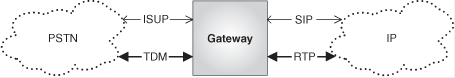
The protocol conversion in the gateway takes place at both the signaling plane and the media plane.
In the signaling plane, the protocol conversion occurs between SIP and ISUP (or BICC).[5]
More specifically, an IP/PSTN gateway can perform two operations at the signaling plane:
Protocol translation back and forth between ISUP and SIP.
ISUP encapsulation in SIP messages, and ISUP decapsulation from SIP messages.
Both protocol translation and encapsulation are described in subsequent sections.
In the media plane, the conversion occurs between RTP, in the IP side, and TDM (Time Division Multiplex) in the PSTN side. It is worth mentioning that TDM and RTP will still contain PCM[6] -encoded voice.
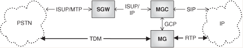
An IP/PSTN gateway can be split into the following components:
The Media Gateway (MG[7]): It is the entity that performs the interworking at the media plane between the IP and PSTN domains. It is controlled by the MGC.
The Media Gateway Controller (MGC): It is the entity that controls the Media Gateway. It also performs the mapping, at the application level between the signaling protocols (ISUP-SIP), in the IP and PSTN domains. The MGC is sometimes referred to as a “softswitch” or “call agent.”
The Signaling Gateway (SGW): It is the entity that performs the signaling interworking at the transport level (MTP[8] -SCTP/IP) between the IP and PSTN domains.
The standard protocol used by the MGC to control the MG is called Gateway Control Protocol (GCP) specified in [RFC 3525] and [H.248.1].
The split-GW components are shown in Figure 18.2.
Let us now see the architecture for the different scenarios.
In this scenario, in addition to the need for a gateway that performs protocol translation, we need to tackle two additional aspects:
How to address a PSTN user from an IP endpoint.
How to route the call to the gateway.
The first aspect is resolved by having the IP endpoint use a new type of URI, the TEL URI, which will be discussed in the next sections.
Unless a SIP UA connects directly to a PSTN gateway, the second aspect is resolved by the SIP network, typically by the outbound SIP proxy for the originating user. The proxy translates the telephone like address (TEL URI) into a SIP URI, with the host part of that URI pointing to a gateway. There are several different options in order to implement such a translation:
The proxy server may translate all TEL URIs into the same SIP host name.
The proxy server may select a different gateway for different TEL URIs prefixes based on static configuration.[9]
The proxy server may use a gateway location protocol such as TRIP to select a gateway. TRIP (Telephony Routing over IP Protocol) is defined in [RFC 3219], and is part of the framework for gateway location defined in [RFC 2871].
Option 1 is used in small deployments. Option 2 is frequently used by VoIP service providers. Option 3 is conceived to cope with more-generic cases of Internet-wide provision of VoIP services and deployment of gateways.
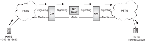
Figure 18.3 shows the architecture for Scenario 1. In the figure, we refer to the legacy PSTN phones as POTS (Plain Old Telephone System) terminals, which is a common terminology.

In this scenario, in addition to the need for a gateway that performs protocol translation, we also need to consider:
How to address an IP user from a PSTN telephone.
How to route the call from the gateway to the IP endpoint.
Regarding the first aspect, PSTN phones do not offer the capability of entering a sip or sips URI, but just a collection of digits that represent a telephone number. Therefore, in order to enable this scenario, we need to allocate telephone numbers to IP users who want to have the possibility of receiving calls from the PSTN. In other words, these users will need to have a TEL URI identity (possibly in addition to the SIP URI identity). The gateway would receive a telephone address, would convert it into a TEL URI, and would resolve the TEL URI into SIP URI by using an ENUM query. ENUM service is described in subsequent sections. Once the gateway has a SIP URI identifying the IP user, routing proceeds as per normal SIP mechanisms.
This scenario is depicted in Figure 18.4.
Scenario 3 implies that a call originated in the PSTN and addressed to a PSTN endpoint is transited through an IP infrastructure. A typical reason for doing this is for transmission cost optimization. Instead of using a TDM network to route the calls between PSTN users, the operator may want to leverage existing cheaper IP infrastructure (Figure 18.5). Another common reason is that the operator may want to apply enhanced telephony services to its customers (Figure 18.6). These services may be difficult to implement in a pure PSTN environment, whereas they might be easily enabled in an IP and SIP domain. As an example of this, just consider telephony services that require complex call leg manipulation. In the PSTN, the IN[10] standards needed to support those functions are not widely implemented or are very expensive, whereas SIP natively supports those functions, and SIP applications can be easily developed over cost-effective SIP application servers.

In this scenario, in addition to the protocol translation, addressing, and routing functions that we saw in previous scenarios, there is the need to transparently carry the ISUP signaling within SIP messages. That is referred to as the protocol encapsulation function, and it is critical so as not to lose any PSTN functionality during the IP transit. ISUP encapsulation is described in subsequent sections.
The TEL URI is a URI scheme defined by [RFC 3966]. It is used to describe resources identified by telephone numbers.
Phone lines in the PSTN are identified by an [E.164] number. In order for a UA to be able to place a call to a PSTN user, it must somehow address the INVITE message to a telephone number. However, we have seen that addresses in SIP are in the form of URIs, mainly sip or sips URIs. In order to overcome this problem, [RFC 3966] defines a new URI scheme called the TEL URI. The TEL URI consists of a telephone number, and identifies a resource in the telephone network. An example of a TEL URI might be:
tel: + 34610456822
Another use of TEL URIs is for allowing calls from PSTN to IP users. PSTN phones do not allow the user to introduce a sip URI in order to place a call to an IP user. In order to enable this scenario, IP users need to be given an identity in the form of a TEL URI so that they can be reached from the PSTN.[11]
A TEL URI complies with the following format:
“tel:” telephone-subscriber
where telephone-subscriber may indicate a global number or a local number.
Global numbers follow the E.164 recommendation from ITU, and are composed by the “+” character followed by a country code (CC) and national subscriber number (NSN). For example, the following URI points to a phone number in the United Kingdom (CC=44):
tel: + 441259551634
Local numbers belong to private numbering plans, and have meaning only within a certain context. They may, for instance, represent extensions within a PBX, or telephones within a certain geographic area. The following example shows a TEL URI that represents an extension within a PBX at ocean.com. TEL URIs representing a local number must include the phone-context element:
tel: 4444; phone-context=pbx1.ocean.com
[RFC 3761] defines a mechanism for using the DNS for storage of E.164 numbers. This mechanism allows resolving telephone numbers into SIP addresses of record.
The solution uses an NAPTR resource record. NAPTR RRs were described in Chapter 6.
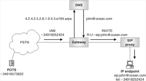
In order to illustrate how it works, let us consider a scenario where Mary, a PSTN user, calls John, who is a SIP user. John has two identities: a SIP URI and a TEL URI. The SIP URI is the identity that he gives to other multimedia users so that they can reach him using SIP, whereas he advertises the TEL URI among his colleagues who, like Mary, still have only an old PSTN phone, so that they also can reach him for simple voice calls.
His TEL URI is:
tel: + 12015551634
and his SIP URI is:
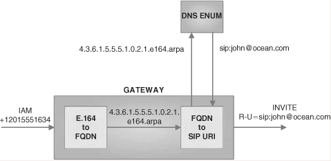
Therefore, Mary dials +12015551634, and the call is routed by the PSTN operator, based on the analysis of the called-party number, to the PSTN/IP gateway. In order to translate the telephone number into a routable SIP URI, the gateway performs the following steps:
Converts the received telephone number into an FQDN by applying the following rules:
Removes the “+” sign.
Puts dots between each digit.
Reverses the order of the digits.
Appends the string “.e164.arpa” to the end.
The resulting domain name would be: 4.3.6.1.5.5.5.1.0.2.1.e164.arpa.
The gateway queries the DNS ENUM system for such a domain name.
DNS ENUM returns a NAPTR record that includes the new sip URI:
Figure 18.7 shows the different steps in this process.
In order to allow the translation between telephone numbers and SIP addresses of record, [RFC 3761] defines an enumservice. The enumservice for SIP is “E2U + sip.” Table 18.1 shows a possible NAPTR record for our previous example.
We can see that the NAPTR query returns a rewrite rule using the regexp field.
In order to convert between SIP and ISUP and vice versa, three aspects need to be considered:
Message mapping
Parameter mapping
State machine alignment
The gateway implements a set of rules that govern the mapping between SIP and ISUP at message level. For instance, one such rule might state that when an INVITE is received in the IP side, an IAM (Initial Address Message) should be sent in the PSTN side.[12] A potential mapping between ISUP and SIP messages has been described in [RFC 3398].
Likewise, the gateway needs to decide how to map signaling parameters from one protocol to the other. Because the protocols do not offer exactly the same functionality, there will be parameters lost in the translation, or some parameters will have to be filled in by the gateway. There are, though, some parameters for which implementing the correct mapping is critical, such as those that carry routing information. For example, the Called Party Number could be mapped onto the SIP “To” header field and Request-URI, and so on.
The protocol translation topic is a complex one and, moreover, requires substantial knowledge about the protocols in the PSTN, which are not the focus of this book. Therefore, we will show just a couple of simple call flows that allow the reader to understand how the mapping works.
The SIP and ISUP protocol state machines also need to be aligned because the message sequence in SIP is not exactly the same as the message sequence in ISUP.
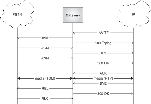
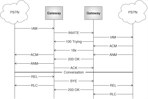
The gateway receives an INVITE message from the IP side, and translates it into an Initial Address Message (IAM). When the telephone rings, the PSTN generates an Address Complete Message (ACM) toward the gateway. The gateway translates it into an 18x provisional response. Later on, the PSTN user answers the call, and the PSTN generates an ANswer Message (ANM), which is translated by the gateway into a 200 OK final response. The IP endpoint will generate an ACK, which has no equivalent in the PSTN.
In order to terminate the session, the IP endpoint sends a BYE request that is converted by the gateway into an ISUP Release (REL) message. The gateway will acknowledge the BYE request as soon as it receives the request. The PSTN will generate a Release Complete (RLC) message as soon as it receives the REL message.
This scenario is shown in Figure 18.8.
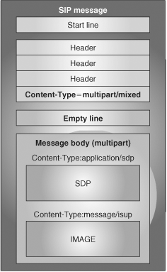
As we saw before, Scenario 3 requires that the ISUP signaling is transparently carried between the ingress and egress gateways. In order to achieve this, the ISUP MIME media type has been defined [RFC 3204].
Therefore, ISUP signaling will be carried in the message body of SIP messages as a MIME object. Given that SIP also needs to transport the SDP content, the actual content carried on SIP will be of type multipart. This is shown in Figure 18.11.
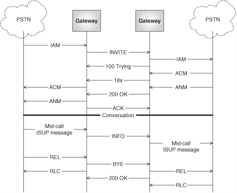
In the protocol encapsulation scenarios, there are cases where a PSTN signaling message is received in the middle of a call and needs to be carried through the IP network to the egress gateway. The question here is: What SIP method to use in order to encapsulate the mid-call ISUP message?
The SIP core specification defines two methods that can be used in the middle of a session. One is re-INVITE, and the other one is BYE. The former updates the session parameters and also modifies the dialog state. The latter terminates the session. Therefore, these methods are not valid for our purposes. What we are looking for is a method that can be used for communicating mid-session signaling information along the signaling path of a call, and that modifies neither the session nor the dialog state.
[RFC 2976] defines a new SIP method, INFO, that can be used to solve this problem. It can be sent by SIP UAs at any moment during the session (provided the UAs support this extension), and it does not modify the dialog state. The mid-call ISUP message is carried in the body of the INFO message.[13] This is shown in Figure 18.12.
At this point, some reader might ask himself or herself: How does the gateway know whether it has to apply just protocol translation (as in Scenarios 1 and 2), or apply both translation and encapsulation (Scenario 3)?
The answer to this question is that the gateway does not know—it will always apply both. This means that in Scenario 2, the User Agent will receive an encapsulated ISUP object that it does not understand. The approach taken by [RFC 3372] and [RFC 3398] is that if the UA does not understand ISUP, it should ignore the ISUP content in the SIP body.
In this chapter, we analyzed an aspect that is critical in order to offer SIP-based voice services: interoperability with the existing fixed (PSTN) and mobile (PLMN) circuit-switched networks. We focused mainly on voice, which is, by far, the main service offered in circuit-switched networks. However, PSTN (or, more precisely, ISDN) and PLMN can also offer circuit-switched-based video services. Video services in the circuit-switched network are considerably more complex than their voice counterparts because they require additional in-band signaling. Consequently, they were not covered in this chapter.
[1] PSTN stands for Public Switched Telephone Network.
[2] PLMN stands for Public Land Mobile Network.
[3] ISUP is the call-signaling protocol used between core network elements in PSTN and PLMN.
[4] TDM stands for Time Division Multiplexing. It is the type of multiplexing that is used in traditional circuit-switched networks. It is based on allocating a different time slot to each individual voice conversation.
[5] Some circuit-switched networks have evolved toward supporting other protocols, such as BICC (Bearer Independent Call Control). BICC is a call control protocol based on ISUP that allows us to offer the same narrowband services that ISUP supports, only over a broadband backbone network.
[6] PCM (Pulse Code Modulation) is a type of voice encoding that is traditionally used in telephone networks. It consists of sampling the voice signal at regular intervals (typically at 8,000 samples per second), and then digitizing each of the samples. PCM encoding can also be transported on RTP, as we saw in Chapter 10.
[7] MG is the terminology used in IETF specs to refer to a media gateway, though, in the industry jargon, it is more frequent to use the term MGW.
[8] MTP (Message Transfer Part) is the layer 2 (link) and 3 (network) protocol traditionally used in circuit-switched networks to carry signaling information.
[9] For instance, based on the TEL URI prefix, different gateways could be selected for breakout to different national networks or to an international point of interconnection.
[10] IN stands for Intelligent Network, and refers to a set of ITU standards for enabling circuit-switched networks (such as the PSTN) with enhanced and customizable call control capabilities. IN for PLMN is referred to as CAMEL and is defined by the 3GPP.
[11] The use of TEL URI to identify SIP users might also be for convenience. When a SIP-to-SIP call is established, the calling party may want to use a telephone number, simply because that’s how he or she knows the other party. In addition, some people may not want to reveal their SIP URI (e.g., [email protected]), but want to hide behind a number.
[12] IAM is the name of the message used for initiating a call in ISUP.
[13] Some examples of ISUP mid-call message are:
Call progress (CPG)
Facility (FAC)
User-to-User (UUS)
CPG and FAC may be used for Supplementary Services (e.g., to indicate call hold to remote party).