
11
The Service Discovery Protocol
A Bluetooth piconet is quite different from a traditional LAN. Rather than connecting to a network, you connect straight to another device. Connections can change quickly, and in this dynamic environment, the structuring normally provided by a network manager is missing.
In a normal LAN, you find a connection to a printer, and once found, it stays in place for months, or years. Bluetooth is designed to allow you to walk into an area and find a printer without having to preconfigure settings. When you’ve used the printer, you can walk away and forget its details. Service Discovery Protocol (SDP) is the part of Bluetooth that allows this to happen. SDP provides the means to find a device that will print for you or to browse through the range of other services Bluetooth devices in the area can offer you.
Figure 11–1 shows SDP’s position in the Bluetooth protocol stack. SDP relies on L2CAP links being established between SDP client and server. Once an L2CAP link has been established, it can be used to find out about services and how to connect to them. L2CAP does not handle connections to services itself, it merely provides information. So, to find and connect to a service offered by an SDP server, a client must go through the following steps:
Figure 11–1 SDP’s position in the Bluetooth protocol stack.
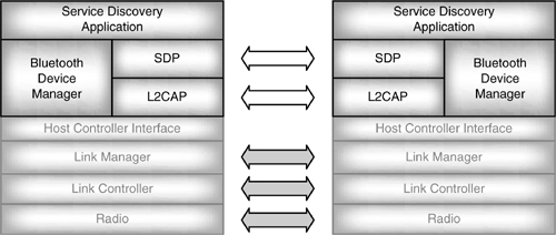
- Establish L2CAP connection to remote device using channel identified by PSM=0x0001.
- Search for specific class of service, or browse for services.
- Retrieve attributes needed to connect to the chosen service.
- Establish a separate (non-SDP) connection to use the service.
The L2CAP channel used for SDP can be dropped once it is no longer needed, or it may be left open if the client is likely to want to query the server’s database for more SDP services.
The L2CAP Protocol and Service Multiplexer (PSM) value for SDP is defined as 0x0001. Having a known PSM means that once an ACL link has been established, the SDP client automatically knows the number to use to establish a link with the SDP server on the remote device.
Bluetooth does not define a man machine interface for service discovery; it merely defines the protocol to exchange data between a server offering services and a client wishing to use them.
11.1 SDP Client/Server Model
An SDP server is any Bluetooth device which offers a service or services to other Blue-tooth devices (a service is a feature usable by another device). Information about services is maintained in SDP databases. Each SDP server maintains its own database; there is no centralized database.
SDP clients use services provided by servers. To allow them to do this, servers and clients exchange information about services using service records.
- A device wanting to find out about services in the area is an SDP client.
- A device offering services is an SDP server. Devices can simultaneously be both clients (using services) and servers (offering services).
11.2 The SDP Database
The SDP database is simply a set of records describing all the services which a Bluetooth device can offer to another Bluetooth device. SDP provides the means for another device to look at these records.
11.2.1 Service Attributes
An SDP service is described by service attributes, which provide the information a client needs to use the service.
Each attribute has a 16 bit identifier and a value, as shown in Figure 11–2. Attribute values can be text strings, Boolean values, or integers.
Figure 11–2 Structure of an SDP service attribute.

Attributes are used to pass information on services and on the hierarchy of services available. Each attribute in the record describes a different aspect of a service. Version 1.0b of the Bluetooth standard defines twenty-eight types of attributes:
- ServiceRecordHandle—A 32 bit number uniquely identifying a service record within a server.
- ServiceClassIdList—The type of services covered by this service record.
- ServiceRecordState—A 32 bit number that is changed whenever any attribute in the record changes. This allows a client to cache information and easily check if it’s up to date.
- ServiceID—A unique identifier for this instance of the service. The same service will have different ServiceID values on different servers.
- ProtocolDescriptorList—The protocols needed to use the service.
- BrowseGroupList—A list of groups used when browsing for services (see section 11.3).
- LanguageBasedAttributeList—A list of languages which a service record supports. Each language listed has a language identifier, an identifier for how characters are encoded, and an attribute ID. Adding a language attribute ID to the attribute ID of a string value gives the attribute ID for retrieving the string in that language.
- ServiceInfoTimeToLive—A 32 bit integer giving an estimate of the number of seconds until the service record will next change (allows clients with cached information to poll for changes).
- ServiceAvailability—An 8 bit integer reflecting the fraction of the maximum number of clients which the service is already serving, roughly (1-(current clients/maximum clients)) *0xFF.
- BluetoothProfileDescriptorList—A list of Bluetooth profiles supported by a service.
- DocumentationURL—A URL for documentation on the service.
- ClientExecutableURL—A URL for an executable that is needed to use the service.
- IconURL—A URL for an icon that the client’s user interface may use to represent the service.
- ServiceName—A string with the service’s name for use by the client’s user interface.
- ServiceDescription—A string describing the service, for use by the client’s user interface.
- ProviderName—A string with the name of the service provider.
- VersionNumberList—A list of versions supported.
- ServiceDatabaseSet—A 32 bit integer which changes when any service record on a server changes. This allows a client to cache information and easily check if it’s up to date.
- GroupId—Identifier for a group of services, used when browsing services (see section 11.3).
- RemoteAudioVolumeControl—Whether remote volume control is supported (for headsets).
- External Network—Used by the cordless telephony protocol to identify the type of telephone network the telephone is connected to. The value is one of: PSTN=1, ISDN=2, GSM=3, CDMA=4, analog cellular=5, packet-switched=6, or other=7.
- Service Version—Version number of the service, e.g., 0x0100 means version 1.00.
- Supported Data Stores List—Used by the synchronization profile.
- Supported Formats List—Used by the object push profile, a list of the formats of objects which can be pushed. The format value is a Uint8 and is one of: phone-book=1, calendar=3, notes=5, messages=6.
- Fax Class 1 Support—Used by the FAX profile; a Boolean describing whether industry-standard Class 1 FAX is supported.
- Fax Class 2.0 Support—Used by the FAX profile; a Boolean describing whether industry-standard Class 2.0 FAX is supported.
- Fax Class 2 Support—Used by the FAX profile; a Boolean describing whether manufacturer-specific Class 2 FAX is supported.
- Audio Feedback Support—Used by the dialup networking profile: a Boolean value which describes whether audio feedback is provided on an SCO channel during call setup.
Some of the attributes are specific to Bluetooth profiles. It is likely that as more Bluetooth profiles are defined, more types of attributes will be defined for them.
11.2.2 Data Elements
Attributes have values, and those values can have various types and sizes. So that a device receiving an attribute knows what type and size it is receiving, attributes are sent in data elements which begin with data element descriptors that describe the type and size of the attribute being sent.
The first byte of a data element contains the data element type descriptors; the first five bits are the data element type descriptor, and the next three bits are the data element size descriptor.
The data element type descriptor gives the type of attribute in the data element. There are nine different types numbered as follows:
- 0—The null type.
- 1—Unsigned integer.
- 2—Signed 2’s complement integer.
- 3—Universally Unique Identifier (UUID).
- 4—String of text.
- 5—Boolean, true or false.
- 6—A sequence of data elements, all of which make up the data.
- 7—A sequence of data elements, one of which must be chosen, called a data sequence alternative.
- 8—Uniform Resource Locator (URL).
The data element size descriptor gives the size of the attribute in the data element. It starts off with a size index. If the size index is 0, 1, 2, 3, or 4, it gives the length of the attribute which follows:
- 0—1 byte, or 0 bytes if it’s a null data element.
- 1—2 bytes.
- 2—4 bytes.
- 3—8 bytes.
- 4—16 bytes.
If the size index is 5, 6, or 7, it is followed by the size:
- 5—Data size is in next 1 byte.
- 6—Data size is in next 2 bytes.
- 7—Data size is in next 4 bytes.
Why have such a complex system where sometimes there is a size field and sometimes there isn’t? It would have been possible to forget about having to always send the size in a 32 byte field, but many attributes will fit into 1, 2, 4, 8, or 16 bytes. Thus, for these attributes, it saves a significant amount of bandwidth to just use the size index and not send a separate size field. The data element type descriptor leaves three spare bits in its byte. These three bits are just enough to use for the size index, so this index isn’t using any extra bytes in the PDU. On the other hand, it’s not possible to avoid sometimes sending the size information separately because attributes which are made up of sequences and attributes which are text strings can be very long, so their length can’t be adequately described by the size indexes.
Examples of data elements are the easiest way to understand how the data element descriptor structures work. Figure 11–3 has an example of a data element containing a 16 bit integer. The first five bits have the type; this is 1, which indicates that the attribute is an unsigned integer. The size index is 1, which says the attribute is two bytes long. The attribute’s data then follows: first the least significant byte, then the most significant byte.
Figure 11–3 Data element containing a 16 bit integer.
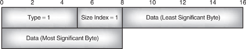
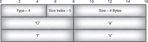
Figure 11–4 has an example of a data element containing the string “Cats”. The first five bits have the type; this is 4, which indicates that the attribute is a text string. The size index is 5, which says the attribute size is in the next byte. The attribute’s size in bytes is then given. Since characters are encoded one byte per character, this size is also the length of the string. The attribute’s data, “Cats,” then follows.
Figure 11–4 Data element containing a text string.
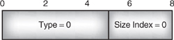
Sometimes there is no attribute data to put in a parameter, but the parameter still has to be sent. In these cases, a null data element is used. A null data element is shown in Figure 11–5; it’s type is 0, indicating a null. The size index is also 0. Normally, this would mean one byte of data, but in combination with the null type, it means that there is no attribute data following.
Figure 11–5 Data element containing a null.
Sometimes a parameter needs to carry several attributes. To do this, a data element sequence or data element alternative is used. Both of these allow a list of attributes to be sent. In a data element sequence, all of the attributes are to be used; in a data element alternative, only one attribute is chosen to be used.
Figure 11–6 shows an example data element sequence. This sequence contains a list of UUIDs—such a list might be sent as a ServiceSearchRequest parameter by a client trying to find out whether a server supported one of a set of services.
Figure 11–6 Data element containing a data element sequence.

The first two bytes describe the sequence: the type is 6 for data element sequence. Because the sequence takes up six bytes, the size doesn’t fit in the size index, so an index of 5 is used to indicate that the size comes in the next byte. The size byte gives the length in bytes of the whole sequence.
Each data element in the data element sequence has its own data element descriptors. Both elements are UUIDs, so they both have a data element type descriptor of 3. Both UUIDs are two bytes long, so both data elements have a SizeIndex of 1.
There is no particular significance to the way the bytes are split up in the diagram; they have just been split up into two byte rows for convenience. However, the splitting up of the Dial Up Networking UUID illustrates the byte order that SDP uses with the most significant byte being sent first and least significant byte sent last.
A data sequence alternative is sent in a similar way, with one set of data element descriptors for the whole sequence, and then a data element descriptor for each data element in the sequence.
11.2.3 Service Records
Attributes are values describing a service which a server is making available to clients. A service record holds all the information a server provides to describe a service, so it is made up of a series of attributes. The class of the service defines the meanings of the attributes, so an attribute might mean something different in different service records.
Table 11–1 shows an example of the Bluetooth headset’s service record, which illustrates how a service record is made up. The first part of the service record deals with the services offered by the device. The headset service is made up of two services: the headset service and the generic audio service on which the headset service is based. The service record then goes on to list the protocols that are needed to use the headset service. The headset service requires L2CAP and RFCOMM. The channel number of the RFCOMM server is needed before a device can access RFCOMM, so along with the protocol descriptor for RFCOMM, there is an extra protocol specific parameter. The client device knows how to use RFCOMM, so it knows that this protocol specific parameter is the channel number; retrieving this number allows the client to begin using RFCOMM.
Table 11–1 Service Records for a Bluetooth Headset

Next comes a BluetoothProfileDescriptorList, which lists the profiles which the service supports. Profiles should only be listed if the device fully supports them, so it is possible for a device to have no list of profiles in any of its service records (for example, a Bluetooth development system may not support any profiles). Naturally, the headset service implements the headset profile, so the unique identifier for this profile is given, followed by a version number. The headset profile is based upon the serial port profile, and all profiles require the generic access profile. But as support of these two profiles is implicit in support of the headset profile, there is no need to explicitly list them. In fact, because the generic access profile is required for all other profiles, it has not even been assigned its own service class UUID in Bluetooth’s assigned numbers, so it is not possible to list it in an SDP service record.
The record finishes with some extra attributes needed to use the headset profile: the name given by the service provider to the headset service, which defaults to “Headset”, but could be changed by the service provider; and finally, an entry to inform the client that this headset does not support the optional feature allowing remote setting of headset volume by an audio gateway.
Note that one ServiceRecord may contain the ServiceName in several languages. The client adds different offsets to the AttributeID to get the attribute in different languages. The device’s primary language is given the offset 0x0100, so to get the Service-Name in the primary language, the client would add 0x0100 to the base ServiceName attribute ID of 0x0000 to give 0x0100.
To find out what the language offsets are for a device, the client would request the LanguageBaseAttributeIDList, which has attribute ID = 0x0006.
11.3 Browsing SDP Records
To make it easier to find the service you want, services are arranged in a hierarchy structured as a tree which can be browsed. Clients begin by examining the root of the hierarchy, then follow the hierarchy out to the leaf nodes, where individual services are described.
It is up to each service provider to decide what services will be browsable and how the browsing hierarchy will be constructed. For example, a smart phone offering several different services to other Bluetooth devices could have the browse structure shown in Figure 11–7.
Figure 11–7 A possible SDP browsing hierarchy for a cellular phone.

The service provider has chosen to organize the services into two groups. The audio group covers audio gateway services, which allow Bluetooth headsets to connect to cellular connections and local Bluetooth intercom connections. The organizer group includes calendar facilities, which include the ability to synchronise calendars and alarms.
An alarm facility is common to many mobile phones, but is not defined under Blue-tooth, so the alarms category shows how SDP can be used to publish information about new services not defined in the Bluetooth specification. A user of the alarms service would have to know something about how it worked so that they could connect to it, but any parameters necessary to connect to this particular instance of the alarms service could be retrieved via SDP. For instance, the alarms service might provide the ability to set alarms via an RFCOMM connection, so the RFCOMM channel for connecting to the alarms service could be retrieved by querying the SDP service records for the alarms service.
11.3.1 Browse Groups and Browse Group Lists
Service classes are used to identify services. Each service class record includes a BrowseGroupList attribute. The value of the BrowseGroupList is a list of the UUIDs of all the browse groups associated with the service.
Table 11–2 shows the set of service records used for browsing the hierarchy in Figure 11–7. Each group entry lists the IDs of any groups above it and its own group ID. The services don’t just list the IDs of the groups they belong to.
Table 11–2 Service Records for a Possible SDP Browsing Hierarchy for a Cellular Phone
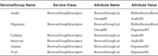
The top level of the browsing tree is called PublicBrowseRoot and has the UUID 0x1002 (this is the short form, the long form of this is 0x00001002-0000-1000-7007-00805F9B34FB). All browsing hierarchies have this top level. Because there is no entry above the PublicBrowseRoot, and all devices know its Group ID, there is no need to include an entry for the PublicBrowseRoot in the table.
11.4 Universally Unique Identifiers (UUIDs)
Universally Unique Identifiers (UUIDs) are 128 bit numbers. Each record has a UUID attribute; these are used to search for a record. The Bluetooth standard specifies UUIDs for the attributes needed for the Bluetooth profiles.
11.4.1 UUIDs Assigned by the Bluetooth Specification
The Bluetooth specification’s UUIDs are likely to be used a lot, so to save bandwidth transferring them and space storing them, they can be shortened to 32 bit or 16 bit forms. This is possible because all the Bluetooth specification’s UUIDs are based in the same Bluetooth base UUID: 0x00000000-0000-1000-7007-00805F9B34FB.
To compare a pair of UUIDs, they must be converted into the same format. The rules for converting UUIDs assigned by the Bluetooth specification are quite simple:
- To convert a 16 bit UUID into a 32 bit UUID, it is just zero-extended to 32 bits. For example, the 16 bit UUID 0x1265 becomes the 32 bit UUID 0x00001265.
- To convert a 16 or 32 bit UUID into a full 128 bit UUID, it is multiplied by 296 and added to the Bluetooth base UUID. For example:
0x1265*296 + 0x00000000-0000-1000-7007-00805F9B34FB = 0x00001265-0000-1000-7007-00805F9B34FB
11.4.2 UUIDs Assigned by Manufacturers
A manufacturer defining a new service is allowed to allocate its own UUIDs. This could easily lead to clashes of IDs, so SDP uses a method of allocating UUIDs which makes them extremely unlikely to be duplicated.
A UUID is made up of the following parts:
- time_low—32 least significant bits of the timestamp (bits 0 to 31).
- time_mid—16 bits of the middle field of the timestamp (bits 32 to 47).
- time_high_and_version—A 16 bit value:
- least significant 12 bits are the most significant 12 bits of the timestamp (bits 48-59).
- most significant 4 bits are the version.
- clock_seq_hi_and_reserved—An 8 bit value:
- 6 least significant bits are the 6 most significant bits of the clock sequence (bits 8 to 13).
- 2 most significant bits are the variant (this may be set to 10).
- clock_seq_low—The low field of the clock sequence.
- node—The unique node identifier.
The unique node identifier is used to guarantee that the UUIDs allocated by one node are different from those allocated by other nodes. A 48 bit IEEE address is used for this field. As these are allocated uniquely, it provides a convenient guarantee that the node ID is unique. Usually, the address used will be the address of the host.
The timestamp is 60 bits of coordinated Universal Time Clock (UTC), which is the number of 100 nanosecond intervals since 00:00:00.00 on 15 October 1582. This may seem like an odd date to pick, but it is the date of the Gregorian reform of the Christian calendar, so it is the start of the most widely used system of dating in use today. This timestamp will not wrap around to zero until around 3400 A.D.
The clock sequence value is used because some systems will not have a real-time clock that is calibrated to a date, or for some other reason their value of the coordinated UTC goes backwards. This could lead to duplication of UUIDs. To get around this problem, the 14 bit clock sequence value is changed every time the UTC value goes backwards and every time the system reboots. Random numbers can be used to make sure the clock sequence value changes if the system can’t store values across a reboot. The clock sequence value ensures that even if the same UTC value is generated twice, the UUIDs will still be different.
The variant field describes the layout of the UUID. Microsoft has reserved a variant ID of 110. Variants beginning with zero are reserved for backwards-compatibility with the Network Computing System (NCS), which originated the UUID system. The variant with MSBs 10 was used in an Internet draft and is used by the DCE 1.1 Remote Procedure Call specification. The binary value 10 is used in the Bluetooth base UUID, and it may be used in the variant field to assign UUIDs for Bluetooth SDP purposes.
The version field describes how a UUID was allocated. The time-based version described here is identified by the binary sequence 00011. There are other ways of assigning UUIDs, based on functions of names or on random numbers. Each method has its own different variant value, so they each produce a different range of UUIDs. This helps to ensure that UUIDs stay unique, whatever method was used to allocate them.
The parts of the UUID are written as a series of hexadecimal digits separated by hyphens in the following order:
UUID = time_low - time_mid - time_high_and_version - clock_seq_hi_and_reserved - clock_seq_low - node
For storage and transferring in a data stream, the UUID is just treated as a sequence of octets.
The full rules on using and assigning UUIDs are available at: http://www.opengroup.org/publications/catalog/c706.htm or http://www.iso.ch/cate/d2229.html, and in the International Organization for Standardization publication ISO/IEC 11578:1996, “Information Technology—Open Systems Interconnection-Remote Procedure Call (RPC)”.
11.5 SDP Messages
To browse service classes or get information about a specific service, SDP clients and servers exchange messages. These messages are carried in SDP Protocol Data Units (PDUs). There are only seven types of SDP PDUs defined, and each has its own PDU ID to identify it:
- 0x01 = SDP_ErrorResponse.
- 0x02 = SDP_ServiceSearchRequest.
- 0x03 = SDP_ServiceSearchResponse.
- 0x04 = SDP_ServiceAttributeRequest.
- 0x05 = SDP_ServiceAttributeResponse.
- 0x06 = SDP_ServiceSearchAttributeRequest.
- 0x07 = SDP_ServiceSearchAttributeResponse.
The client always initiates SDP transactions with a request; the server always answers with a response as shown in Figure 11–8. (Note that some responses may be split across several packets.)
Figure 11–8 Message sequence chart for SDP request and response.

All SDP PDUs share a common structure as explained in section 11.5.1.
11.5.1 SDP Protocol Data Units
SDP uses Protocol Data Units (PDUs) with the structure shown in Figure 11–9. The first byte is an ID, identifying the message in the PDU. This is followed by two bytes of transaction ID. When a client sends an SDP request, it is given a transaction ID; the server copies that transaction ID into the response, so that if the client sends several requests, it can sort out which response goes with which request.
Figure 11–9 Structure of an SDP PDU.
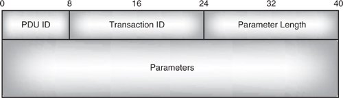
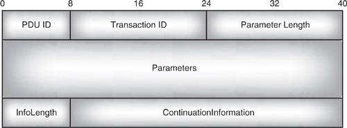
Except for the SDP_ErrorResponse, all SDP PDUs have a ContinuationState as their last parameter. This allows a message to be split across more than one PDU. If the message is not continued, the ContinuationState is a single byte set to zero. If the message is continued, then the first byte of the ContinuationState parameter begins with a single byte length field followed by some ContinuationInformation. The ContinuationInformation is a handle which can be used to request the rest of the message: the client simply repeats the request and copies the ContinuationState parameter from the partial response into the last parameter of the request. When the server receives the request, it uses the ContinuationInformation to identify where it split the response and continues the next response where it left off.
Figure 11–10 shows an SDP PDU with a ContinuationState parameter showing the parameter starting with a single byte of InfoLength, followed by the ContinuationInformation.
Figure 11–10 SDP PDU with ContinuationState parameter.
11.5.2 Searching for Services
Whether a client is starting at the public browse root and searching through the hierarchy of services, or looking for a specific service, it uses an SDP_ServiceSearchRequest. This contains a ServiceSearchPattern made up of UUIDs, which the server is to look for in its database. The server responds with an SDP_ServiceSearchResponse containing information about any service records which match the ServiceSearchPattern as shown in Figure 11–11.
Figure 11–11 Message sequence chart for SDP service search.
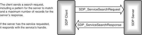
The ServiceSearchRequest has three parameters:
- ServiceSearchPattern, for the server to match in its database.
- MaximumServiceRecordCount, which tells the server the maximum number of records the client wants information on. For instance, if this is set to 2, a server that had six service Records matching the ServiceSearchPattern would only return information on the first two.
- ContinuationState, which tells the server whether the message had to be split across two PDUs.
The structure of an example SDP_ServiceSearchRequest is shown in Figure 11–12. It begins with the header used by all SDP PDUs:
- One byte of PDU ID—0x02 signifies that the PDU carries an SDP_Service-SearchRequest.
- Two bytes of transaction ID—This is copied into the response to the PDU, and helps the client tie the server’s response with this request.
- Two bytes of parameter length—This gives the total length of all the parameters which follow.
Figure 11–12 Structure of an SDP_ServiceSearchRequest.

The header is followed by the message’s parameters: ServiceSearchPattern, MaximumServiceRecordCount, and ContinuationState. The ServiceSearchPattern is made up of several parts.
- Five bits of data element type descriptor = 6 = data element sequence—This tells the server that it is to expect more data elements following.
- In the same byte are three bits of data element size descriptor = 5—This tells the server that the size of the data element sequence is given by the next byte.
- One byte of data element sequence size = 3—This tells the server to expect three bytes of data element sequence before the next parameter.
In this case, the data element sequence just contains one data element, which is made up as follows:
- Five bits of data element type descriptor = 3 = UUID—This is the ID that the server must search for in its database.
- In the same byte are three bits of data element size descriptor = 1—This tells the server that the size of the data element sequence is two bytes.
- Two bytes giving the UUID to search for.
The single UUID completes the ServiceSearchPattern parameter. This is followed by the last parameter:
- Two bytes of MaximumServiceRecordCount = 0x003. There is no need for a size or type parameter, as the server receiving the PDU knows to expect two bytes of parameter here.
The PDU contains a single byte of ContinuationState.
- ContinuationState = 0—This tells the server that this message is a fresh request, not a request for a continuation of data from a previous request.
The ContinuationState is a parameter like all the others, so the parameter length includes the lengths of the ServiceSearchPattern, the MaximumServiceRecordCount, and the ContinuationState.
Note that the ServiceSearchPattern parameter can contain up to twelve UUIDs. Because its length can vary, it begins with data element type and size descriptors, giving the length of the sequence of UUIDs. In this example, there is only one UUID, and since UUIDs can vary in length, it too must begin with data element type and size descriptors to let the server know its length. The other parameters have fixed types and lengths, so they don’t have to have data element type and size descriptors.
11.5.3 Responding to a Search for Services
A server receiving a valid SDP_ServiceSearchRequest replies with an SDP_Service-SearchResponse. This has four parameters:
- TotalServiceRecordCount—The total number of ServiceRecordHandles the server is sending. If the response is split into several PDUs, this is the sum of handles in all response PDUs.
- CurrentServiceRecordCount—The total number of ServiceRecordHandles in this PDU.
- ServiceRecordHandleList—A list of handles for services which match the Service-SearchRequest.
- ContinuationState—Whether the message had to be split across two PDUs.
The structure of an example SDP_ServiceSearchResponse is shown in Figure 11–13. (There is no significance to the way the structure has been drawn with different numbers of bytes on different lines; the diagram has just been broken up into rows at convenient places.) The SDP_ServiceSearchResponse begins with the header used by all SDP PDUs:
Figure 11–13 Structure of an SDP_ServiceSearchResponse.
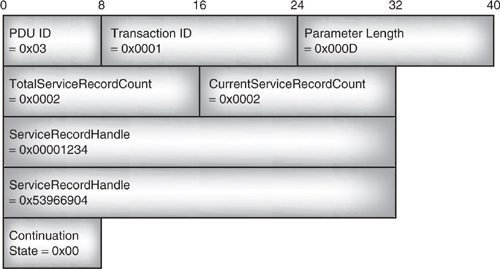
- One byte of PDU ID—0x03 signifies that the PDU carries an SDP_Service-SearchResponse.
- Two bytes of transaction ID—This is copied from the request PDU and helps the client tie this response with the correct request.
- Two bytes of parameter length—This gives the total length of all the parameters which follow.
The header is followed by the message’s parameters: TotalServiceRecordCount, CurrentServiceRecordCount, ServiceRecordHandleList, and ContinuationState:
- TotalServiceRecordCount = 2—Since the request asked for the headset service with a MaximumServiceRecordCount of 3, the client can work out that the handles for all instances of the headset service are being returned.
- CurrentServiceRecordCount = 2—This tells the client that the next parameter contains two ServiceRecordHandles. From the TotalServiceRecordCount, the client can work out that this is all the ServiceRecordHandles.
- The ServiceRecordHandleList contains a series of 32 bit ServiceRecordHandles. These are just integers which uniquely identify each service the server is offering. Because the list has to contain handles, and the handle size is fixed at 32 bits, there is no need for a data element type descriptor or a data element size descriptor, the handles can just be sent as a list of 32 bit numbers.
- Finally, one byte of ContinuationState is set to 0—This tells the server that the whole message is carried in this PDU, that is to say, there will be no continuation.
The service handles returned by this message can be used to request the SDP server for the service’s attributes.
11.5.4 Requesting the Attributes of a Service
Once a client has a service’s handle, it can use an SDP_ServiceAttributeRequest to retrieve the service’s attributes. Figure 11–14 shows an example of such a request. It begins with the header used by all SDP PDUs:
Figure 11–14 Structure of an SDP_ServiceAttributeRequest.

- One byte of PDU ID—0x04 signifies that the PDU carries an SDP_ServiceAttribute-Request.
- Two bytes of transaction ID—This is copied into the response to the PDU, and helps the client tie the server’s response with this request.
- Two bytes of parameter length—This gives the total length of all the parameters which follow.
The header is followed by the message’s parameters—ServiceRecordHandle, MaximumAttributeByteCount, AttributeIDList, and ContinuationState.
- The ServiceRecordHandle identifies the service for which attributes are being requested.
- The MaximumAttributeByteCount sets a limit on the number of bytes of attributes the server can respond with.
- The AttributeIDList identifies the attributes the client is requesting. Because several attributes can be requested, it is a sequence of data elements and begins with a data element descriptor identifying the parameter as a data element sequence. In this case, there is only one parameter, the AttributeID for a ProtocolDescriptorList. This is 0x0004, which is a 16 bit integer, so its data element Descriptor identifies it as an unsigned integer with a length of two bytes.
- ContinuationState is set to 0—This tells the server that this message is a fresh request, not a request for a continuation of data from a previous request.
11.5.5 Responding to a Request for the Attributes of a Service
The SDP_ServiceAttributeRequest in section 11.5.4 asked for the ProtocolDescriptorList associated with a headset service. Table 11–1 shows that a headset service record has a ProtocolDescriptorList with two protocols: L2CAP and RFCOMM, and the RFCOMM protocol has one parameter associated with it: the server channel number used for the headset service.
Figure 11–15 shows how the headset’s ProtocolDescriptorList is fitted into a SDP_ServiceAttributeResponse. The PDU begins with the header used by all SDP PDUs:
Figure 11–15 Structure of an SDP_ServiceAttributeResponse.

- One byte of PDU ID—0x05 signifies that the PDU carries an SDP_ServiceAttribute-Response
- Two bytes of transaction ID—This is copied from the request PDU and helps the client to tie up this response with the correct request.
- Two bytes of parameter length—This gives the total length of all the parameters which follow.
The header is followed by the message’s parameters: AttributeListByteCount, AttributeList, and ContinuationState:
- AttributeListByteCount gives the total number of bytes in the AttributeList. This must be no larger than the MaximumAttributeByteCount sent in the SDP_ServiceAttributeRequest.
The AttributeList parameter is split up into several parts:
- The Attribute List begins with a data element type descriptor identifying the AttributeList as a sequence of data elements and a data element size descriptor giving the total length of the sequence of elements. Because the sequence is fifteen bytes long, it can’t be described by the SizeIndex, so the SizeIndex is set to 5, indicating that the size is given in the following byte.
- The first data element in the sequence is an AttributeID, which identifies the following elements as a ProtocolDescriptorList.
- The first protocol supported is L2CAP. Because a ProtocolDescriptor can contain parameters, it is passed as a sequence of data elements, so it begins with a data element descriptor for a sequence. In the case of L2CAP, there are no parameters, so the list has a single data element which contains the UUID for the L2CAP protocol.
- The second protocol supported is RFCOMM. Again it begins with a data element descriptor for a sequence. In the case of RFCOMM, there is a parameter, so the list has two data elements: the UUID for the L2CAP protocol and the RFCOMM server channel number for the headset service.
- Finally, one byte of ContinuationState is set to 0—This tells the server that the whole message is carried in this PDU, that is to say, there will be no continuation.
11.5.6 Searching for a Service with an Attribute Request
Sections 11.5.2 and 11.5.4 described how a client searches for a service and how a client requests the attributes of a service. Sections 11.5.3 and 11.5.5 described how the server responds to those requests. Often clients wanting to connect to a service will want to find out the services available and some of their attributes. To speed up the process, SDP offers a message which combines a service search with an attribute request.
Figure 11–16 shows an example of an SDP_ServiceSearchAttributeRequest. It begins with the header used by all SDP PDUs:
Figure 11–16 SDP_ServiceSearchAttributeRequest message.
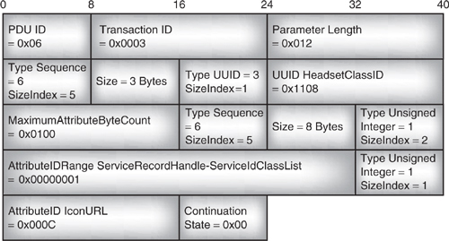
- One byte of PDU ID—0x06 signifies that the PDU carries an SDP_Service-SearchAttributeRequest.
- Two bytes of transaction ID—This is copied into the response to the PDU, and helps the client tie the server’s response with this request.
- Two bytes of parameter length—This gives the total length of all the parameters which follow.
The header is followed by the message’s four parameters: ServiceSearchPattern, MaximumAttributeByteCount, AttributeIDList, and ContinuationState.
- ServiceSearchPattern—Like the pattern in the SDP_ServiceSearchRequest, this is a sequence of patterns to search for, so it begins with the data element descriptors for a sequence. In this case, there is one element in the sequence: the UUID for the headset class. This is prefixed by its own data element descriptors giving its type (UUID) and size (2 bytes).
- MaximumAttributeByteCount—This gives the maximum number of bytes of attribute data the server is to return in response to this request. This parameter has a fixed format; it is always a 16 bit unsigned integer, so it is just sent as two bytes of data. It does not need to be sent as a data element and does not need a data element descriptor.
- AttributeIDList—Like the AttributeIDList in the SDP_ServiceSearchRequest, this is a list of attributes to retrieve from a service, except here the service is specified by the ServiceSearchPattern instead of by a handle. Since the parameter can contain a series of attributes to match, it begins with the data element descriptor for a sequence. This is followed by a series of AttributeIDs and/or AttributeIDRanges. An AttributeID is a 16 bit integer, so if the data element size descriptor has a SizeIndex=1, the data element contains two bytes and must be an AttributeID. If the data element size descriptor has a SizeIndex=2, the data element contains four bytes and must contain a pair of AttributeIDs specifying an AttributeIDRange. In the example below, the AttributeIDList contains one AttributeIDRange, which goes from ServiceRecordHandle = 0x0000 to ServiceIdClassList = 0x0001, the list also contains an IconURL attribute.
- ContinuationState is set to 0—This tells the server that this message is a fresh request, not a request for a continuation of data from a previous request.
11.5.7 Responding to a Search for a Service with an Attribute Request
Figure 11–17 shows an example of how the headset service’s ServiceRecordHandle and ServiceClassIdList can be fitted into a pair of SDP_ServiceSearchAttributeResponses. The response has been split across two response packets. This may have to be done because the SDP PDU size may be larger than the L2CAP Maximum Transmission Unit (MTU), or memory limitations in an embedded device may make it easier for it to generate a series of small responses rather than one large response.
Figure 11–17 ServiceSearchAttributeResponse message with ContinuationInformation.
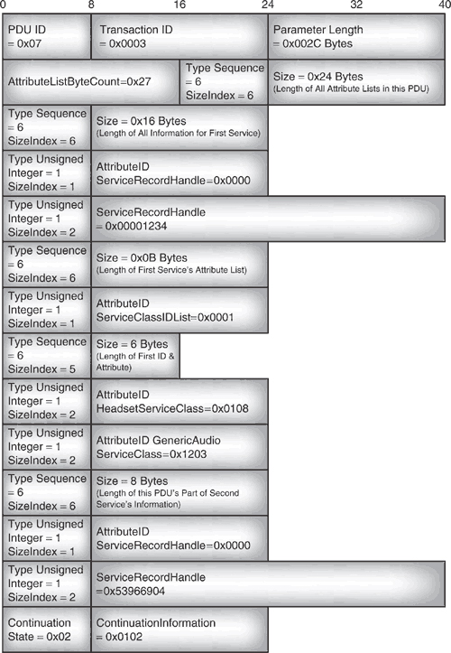
The structure is similar to the examples above, using the standard header followed by the parameters AttributeListByteCount, AttributeLists, and ContinuationState.
Note that the AttributeLists parameter is made up of a sequence of two data elements: the information retrieved for the first service and the information retrieved for the second service. (The information for the second service is incomplete because it is continued in another PDU.) This means that the AttributeLists parameter’s data element descriptor gives its type as a sequence of data elements.
The information on the first service is also a data element sequence, because it also has two data elements: the Service RecordHandle and the attribute list for the first service. The ServiceRecordHandle is a 32 bit unsigned integer, but the attribute list is again a sequence of data elements; in this case, the attributes requested for that service.
So, the PDU’s AttributeIDList consists of nested data elements with sequences inside sequences inside sequences until finally the attributes of services matching the search pattern are reached.
The example PDU given in Figure 11–17 has ContinuationState = 2, indicating that the PDU does not have a complete response and that there are two bytes of Continuation-Information. When the client receives the ServiceSearchAttributeResponse with a nonzero continuation state, it reads the ContinuationInformation, and to get the second part of the response, the client reissues the SDP_ServiceSearchAttributeRequest with the ContinuationState ContinuationInformation copied into the end of the PDU (see Figure 11–18).
Figure 11–18 ServiceSearchAttributeRequest message with ContinuationInformation.

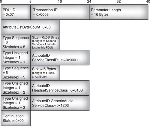
The SDP server receives the second request with a non-zero ContinuationState and uses the ContinuationInformation to work out where it stopped sending data in the first PDU. It can then send the rest of the data in a continuation PDU. Since this is the last PDU in the sequence, it has a zero value for ContinuationState.
In the second PDU, in Figure 11–19, there is only an attribute list for one service. Since there is no list of attributes for several services, and no list of service handle followed by service attributes, there are not so many levels of nested sequence data elements. Note: for simplicity, our example response omits the IconURL, so does not match the example request.
Figure 11–19 Continuation of a ServiceSearchAttributeResponse.
11.5.8 Handling Errors
If an SDP server receives a request which it can’t respond to correctly, it replies with an SDP_ErrorResponse. This carries two parameters: an ErrorCode and additional ErrorInfo.
In version 1.0b, the format of the ErrorInfo is not defined. It is difficult to know what to do with an undefined parameter. One possibility is to ignore it, but since some sort of ErrorInfo parameter is specified, some implementations might regard it as an error if one isn’t supplied, so perhaps a better solution is to send a null data element as illustrated in Figure 11–20.
Figure 11–20 Structure of an SDP_ErrorResponse PDU.
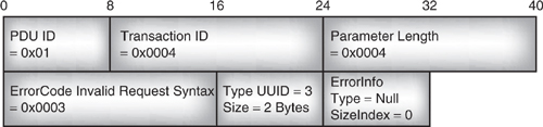
There are six possible values specified for ErrorCode:
- 0x0001—The SDP client is using an invalid or unsupported version of SDP.
- 0x0002—The request contained an invalid ServiceRecordHandle.
- 0x0003—The syntax of the request was incorrect.
- 0x0004—The PDU size of the request was invalid.
- 0x0005—The continuation state of the request was invalid.
- 0x0006—The server has insufficient resources to respond correctly to the request.
The example shown in Figure 11–20 has ErrorCode 3, which shows that it is a response to a request with invalid syntax.
11.6 Service Discovery Profile
The service discovery profile describes how applications running on an SDP client use SDP and other features of the Bluetooth protocol stack to discover services provided by Bluetooth devices within range.
The service discovery profile provides:
- A series of service primitives which an application can use to drive service discovery.
- Example operational frameworks, which are sequences showing how an application might inquire for devices, connect to them, and use service discovery in response to a user’s input.
- Message sequence charts showing the stages in setting up and using an SDP connection.
- A statement that devices supporting the SDP application profile must support pairing and authentication (though the profile does not impose particular requirements for them to be used).
Figure 11–21 shows how the various layers of the stack must each connect in turn to set up an SDP session. The SDP application profile gives examples of when these connections might be set up; for instance, a client might already be connected when it begins an SDP session, or it might only connect in response to a user requesting information.
Figure 11–21 Stages in setting up an SDP session.
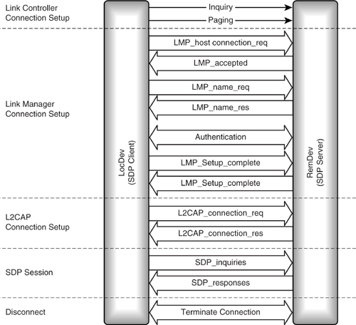
The primitives provided in the service discovery application profile include ServiceBrowse and ServiceSearch, which simply use SDP’s browsing and searching capabilities. There is also an enumerateRemDec primitive, which causes an inquiry and results in the application reporting the other Bluetooth devices in the neighborhood. Finally, there is a terminatePrimitive, which causes the link to a device to be torn down after the SDP application has finished with it.
11.7 Summary
The Service Discovery Protocol (SDP) provides a means for an SDP client to access information about services offered by SDP servers. A server can be any Bluetooth device offering a service which can be used by another Bluetooth device, and a client can be any device wanting to use a service. So, a device could be an SDP client and server at the same time.
SDP servers maintain a database of service records. Each service record provides information that a client needs to access a service. This information may include URLs for executables, documentation, and icons associated with the service. So, a client may have to follow these URLS and retrieve information from elsewhere to be able to use the service.
To use SDP, an L2CAP channel must be established between the SDP client and server. This channel has a protocol service multiplexer reserved for SDP, so that any device can easily connect to the SDP service on another device. After the SDP information has been retrieved from the server, the client must establish a separate connection to use the service (the connection used for SDP cannot be used for anything else).
Services have Universally Unique Identifiers (UUIDs) which describe them. The services defined by the Bluetooth profiles have UUIDs assigned by the standard, but service providers can define their own services and assign their own UUIDs to those services. The UUIDs are allocated by a method that guarantees they will not be duplicated, so there is no need for a central authority or a central database to allocate the UUIDs.
A UUID can be sent in a message asking a server if it supports the service identified by the UUID. Alternatively, instead of asking for a specific service, SDP can provide a mechanism for organising services in trees, along with messages for browsing through the trees to look for a service.
SDP does not define the applications needed to drive the service discovery process, nor does it define an interface to applications; this is left up to implementers. If required, it may be used alongside other service discovery methods which provide Application Programming Interfaces (APIs) such as salutation or SLP (Service Location Protocol).