
16
Low-Power Operation
Many Bluetooth devices will be battery powered. Because a Bluetooth radio can use up to 30 mA when receiving, it is important that it be used as little as possible to save battery power. Bluetooth provides low-power modes of operation to minimise nonessential operation and conserve power.
It can take several seconds to set up an ACL link, so once one has been established, devices which are likely to have more data to transfer don’t want to lose it and have to go through the delay of setting it up again. For instance, if a headset is connected to a cellular phone, it is vital that the headset can pick up a call quickly before the caller decides that nobody’s listening and hangs up. But in between calls there are long periods when no data needs to be transferred, and leaving the handset and headset fully connected would run down their batteries.
The need to keep connections going for fast response conflicts with the need to maximise battery life. The Bluetooth specification solves this dilemma by providing low-power modes. These allow devices to keep connections, but switch off receivers for as long as possible. There are three low-power modes:
- Hold—Allows devices to be inactive for a single short period.
- Sniff—Allows devices to be inactive except for periodic sniff slots.
- Park—Similar to Sniff, except parked devices give up their active member address.
The radio is the biggest power drain on a Bluetooth device, but the Voltage Controlled Oscillator (VCO) that drives the Bluetooth clock is another power hungry component which can be switched off. For devices with requirements for maximum power saving, the Bluetooth specification provides the means to switch to a less accurate lower power oscillator (LPO) when the accuracy of the normal oscillator is not needed.
16.1 Controlling Low-Power Modes
A host can check the link policy settings on a module by sending the HCI_Read_Link_Policy_Settings command. Because link policy can be different on each ACL connection, the command takes a Connection_Handle parameter to specify which connection’s link policy is being read. This handle must belong to an ACL (data) connection, not a SCO (voice) connection. The Connection_Handle and the link policy for that handle are returned in an HCI_Connection_Complete event.
The HCI_Write_Link_Policy_Settings command can be used by a host to control power saving settings on a Bluetooth module. The settings are configured on a per connection basis, so the command takes a Connection_Handle parameter as well as link policy settings. Because power saving can only be used on ACL (data) connections, the Connection_Handle parameter must be the handle of an ACL connection. This command can be used to independently disable or enable each of the low-power modes (the same command is also used to control whether or not Master Slave switch is enabled or disabled).
16.2 Hold Mode
Hold mode is used to stop ACL traffic for a specified period of time. It does not affect SCO traffic. An example of when Hold mode might be used is if a device wanted to perform an inquiry, page, or scan operation. These operations take up all the ACL slots for a known length of time, so the link may as well be held, allowing the device at the other end to switch off its receiver.
A hold message does not order a device to switch off its receiver during ACL slots; it is left entirely up to the held device to decide what to do in the free slots.
16.2.1 Requesting Hold Mode
Both Master and Slave can force or request Hold mode. A connection enters Hold mode because of a request from the local host, because a link manager at the remote end of a connection requested it to hold, or because the local link manager autonomously decided to put the connection in Hold mode.
A device may have several active connections, either because it is a Master with several Slaves, or because it is active on more than one piconet. A complete device enters Hold mode when all of its connections are in Hold mode.
The HCI_Hold_Mode command is used by the host to ask a module’s Link Manager to put a specific connection into Hold mode. This command takes three parameters:
- Connection_Handle—Identifies the connection to be put into Hold mode. The connection handle must belong to an ACL (data) connection; SCO (voice) connections cannot be held.
- Hold_Mode_Max_Interval—The longest time the connection should be held.
- Hold_Mode_Min_Interval—The shortest time the connection should be held.
The Bluetooth module will take some time to process this command, as negotiation between link managers is needed to put a device into Hold mode. So the module acknowledges the HCI_Hold_Mode command with an HCI_Command_Status event, then when Hold mode is finally entered, the module sends its host an HCI_Mode_Change event. The host sets minimum and maximum values for time in Hold mode, so it does not know the actual time which was negotiated. The HCI_Mode_Change event tells the host what value was negotiated for the hold time.
If the module has more than one active connection, this command only affects one connection; the other connections are still active. If the module only has one active connection, then the command stops all ACL traffic.
By default, a Bluetooth device in Hold mode maintains its current power state; however, a host can set the activities a module can perform during Hold mode, enabling it to save power. This is done with the HCI_Write_Hold_Mode_Activity command. Possible settings are:
- Maintain the current power state (this is the default).
- Suspend page scan.
- Suspend inquiry scan.
- Suspend periodic inquiries.
When all of a device’s connections are in Hold mode, these settings provide an opportunity for power saving. If a module is set to not do page scan, inquiry scan, and periodic inquiries, then it can enter a low-power state for the period during which it will be held.
A host can check the settings for Hold mode activity on its module by sending the HCI_Read_Hold_Mode_Activity command.
16.2.2 LMP Negotiations for Hold Mode
The Bluetooth devices at either end of the connection have to agree on the time for which the connection will be held. The Link Manager handles negotiating timing of Hold mode between devices.
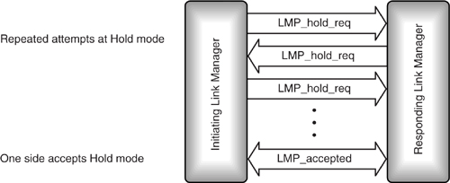
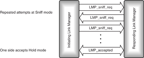
An LMP_hold_req message is used to request Hold mode. It includes parameters for the hold time (length of hold) and hold instant (when to start). When one side requests Hold mode, the other side has three choices: it can accept the hold request with an LMP_accepted, reject it with LMP_not_accepted, or return the request with a different hold time. LMP_hold_req messages can be sent back and forth until one side sends an LMP_accepted or LMP_not_accepted, as shown in Figure 16–1.
Figure 16–1 LMP message sequence chart for requesting Hold mode.
In version 1.0b of the specification LMP_hold and LMP_hold_req messages did not have the hold instant parameter, this could cause problems. For example, a Master could ask a Slave to hold, and the Slave would send a response that then got lost. The Master would then continue trying to hold the Slave, while the Slave was inactive. If the link supervision timeout didn't elapse, the Master would still be trying to hold the Slave when it came back out of Hold mode, so the Slave would exit Hold mode only to go straight back in again. Obviously, this sort of thing can waste a lot of bandwidth, so the hold instant parameter was added to specify exactly when the hold should happen. That way, if the link controller sends a stale LMP_hold message, the receiving device can see that the message is out-of-date because the hold instant will be in the past. To give the message a chance to work its way through from one link manager to the other, the hold instant must be set to at least 6*Tpoll slots in the future.
Hold mode is forced with an LMP_hold from the Master. The Master can only force Hold mode if the Slave has previously accepted a request for Hold mode. The Hold mode time in the LMP_hold message can be no longer than a hold time the Slave has previously accepted in a LMP_hold_req. The Slave cannot force Hold mode, it may only request the Master to hold.
If a Slave wishes to request Hold mode, it sends an LMP_hold to the Master, this message specifies the hold time (length of hold), and the hold instant (when to start). The Master echoes the LMP_hold back to the Slave as shown in Figure 16–2.
Figure 16–2 LMP message sequence chart for forcing Hold mode.

While a Slave is in Hold mode, its clock free-runs and drifts out of synchronisation with the Master. So when it returns from Hold mode, it must open its correlators over a wider uncertainty window. Bluetooth clocks are allowed 10μS jitter, meaning that at any time, the slot start can be 10μS too soon or too late (this is the reason for the +/- 10μS window normally used for reception). In addition, the clock can drift by up to 250ppm. So device going into Hold mode, it has a default uncertainty window of +/- 10μS. After a 1s hold time, its own clock can have drifted by 250 microseconds, and the clock at the other end could have drifted in the other direction by 250 microseconds. So the device returning from hold must add 500 microseconds to its uncertainty giving a window of +/- 510μs.
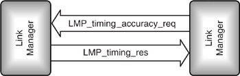
Some Bluetooth devices will have more accurate clocks than the worst case the standard permits. A device always knows its own clock accuracy, but if it can find out the accuracy at the other end of the link too, then it can minimise the scan window for a given hold time. The LMP_timing_accuracy_req message can be used to request the accuracy of the clock at the opposite end of the link; an LMP_timing_res message responds with the clock’s accuracy, as shown in Figure 16–3.
Bluetooth devices don’t have to support the LMP_timing_accuracy_req message. If they don’t, they respond to an LMP_timing_accuracy_req message with LMP_not_accepted containing an error code of LMP_unsupported_feature, and the requesting device has to assume that it is dealing with worst case timings.
16.3 Sniff Mode
Sniff mode is used to reduce traffic to periodic sniff slots. This mode can be used to save power on low data rate links. For example, consider the case of a PDA which needs to receive email from a data-enabled mobile phone. Normally, there would be no traffic on such a link, but when there is traffic, the PDA needs to be ready quickly. Sniff mode can be used to allow the PDA to reduce the slots in which it has to listen, but to react fast when traffic appears.
Figure 16–3 Message sequencing chart for requesting timing accuracy.
16.3.1 Sniff Mode Timing
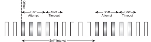
A device in Sniff mode only wakes up periodically in prearranged sniff slots. The Master and Slave must negotiate the timing of the first sniff slot (Dsniff) and the interval at which further sniff slots follow (Tsniff). They also negotiate the window in which the sniffing Slave will listen for transmissions (Nsniff attempt) and the sniff timeout.
The sniffing Slave listens for traffic during the sniff slots determined by the sniff attempt parameter (coloured dark grey in Figure 16–4). If no message addressed to the sniffing Slave is received, the sniffing Slave ceases listening for packets. If a message with the sniffing Slave’s active member address is received, it continues listening for further sniff timeout slots after the sniff slot.
In the example of a PDA wanting to receive email from a mobile phone given above, the mobile would be the Master and the PDA the sniffing Slave. The mobile could use the sniff slots to send a command to unsniff the PDA; after the email had been sent, the mobile could then force the PDA back into Sniff mode.
Alternatively, the sniff timeout could be set to a value large enough to transmit as much data as the phone needs to send. An extreme case would be setting the sniff timeout large enough to keep the sniffing Slave listening throughout the sniff interval. In this way, once a packet had been sent to the Slave in the sniff slot, it would automatically keep listening throughout the transmission.
Because Bluetooth’s radio links are unreliable, the sniff attempt window should be wide enough to give the Master a chance to retry transmissions to the sniffing Slave if necessary. (The size of the broadcast window might be a good size to pick for this, as the broadcast window is set to give enough retries to give a reasonable guarantee of reception.)
Figure 16–4 Timing of Sniff mode slots.
16.3.2 Requesting Sniff Mode
A device enters Sniff mode because of a request from its own host, or because a link manager at the remote end of a connection requested or forced it to enter Sniff mode. (Masters can force Slaves into Sniff mode; Slaves can only request that they enter Sniff mode, and must get the Master’s consent.)
The HCI_Sniff_Mode command is used by the host to ask a module’s link manager to put a specific connection into Sniff mode. This command takes five parameters:
- Connection_Handle—Identifies the connection to be put into Sniff mode. Only ACL connections can be put into Sniff mode, so this must not be an SCO connection handle.
- Sniff _Max_Interval—The maximum time between sniff periods.
- Sniff _Min_Interval—The minimum time between sniff periods.
- Sniff_Attempt—Time at the end of a sniff interval during which a Slave listens for transmissions.
- Sniff_Timeout—If a Slave receives during the sniff attempt time, it keeps listening until the sniff timeout time elapses.
In version 1.1 of the Bluetooth specification the Sniff Attempt and sniff timeout parameters are expressed as the number of receive slots. In version 1.0b they were specified as slots, some implementors counted transmit and receive slots, some just counted receive slots, so by explicitly specifying receive slots version 1.1 has cleared up an ambiguity which led to some 1.0b implementations having timeouts twice as long as others. This change has helped to make sniff mode more interoperable in version 1.1.
The Bluetooth module will take some time to process this command, as negotiation between link managers is needed to put a device into Sniff mode. So the module acknowledges the HCI_Sniff_Mode command with an HCI_Command_Status event, then when Sniff mode is finally entered, the module sends its host an HCI_Mode_Change event. The host sets minimum and maximum values for the sniff interval, so it does not know the actual sniff interval which was negotiated. The HCI_Mode_Change event tells the host what value was negotiated for the sniff interval.
If a host wishes to end Sniff mode for a connection on its module, it simply sends the HCI_Exit_Sniff_Mode command. This command only needs one parameter: the connection handle of the connection to be removed from Sniff mode.
16.3.3 LMP Negotiation for Sniff Mode
Sniff mode applies to a connection, so the devices at either end of the connection must share the same parameters for Sniff mode. The Link management protocol is used to coordinate Sniff mode at either end of a connection as shown in Figure 16–5.
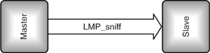
In version 1.0b the Link Manager of the Master could force the Slave into Sniff mode using an LMP_sniff message. The Slave was not allowed to refuse the request, so did not need to reply with an LMP_accepted. This feature was removed in version 1.1 because many implementations could not support all possible combinations of sniff parameters. In particular many implementations had problems staying synchronised if there were long periods of inactivity between sniff slots (that is to say large values of Tsniff). If the Master forces Sniff mode, it has no way to know if the Slave can support the parameters it has supplied, so it may force parameters that the Slave cannot handle. To solve this problem the forced sniff feature was removed from version 1.1 of the Bluetooth specification, so Sniff mode must always be negotiated. Because the option of negotiating Sniff mode is still available, there is no real loss in functionality by removing the LMP_sniff message, so it is a good idea to avoid forcing Sniff mode even when using implementations before version 1.1.
Figure 16–5 LMP message sequence chart for Master-forced Sniff mode (preversion 1.1 only).
Negotiation of Sniff mode is similar to negotiation of Hold mode. An LMP_sniff_req message is used to request Sniff mode. When one side requests Sniff mode, the other side has three choices: it can accept the sniff request with an LMP_accepted, reject it with LMP_not_accepted, or return the request with different timing parameters. LMP_sniff_req messages can be sent back and forth until one side agrees to Sniff mode by sending an LMP_accepted as shown in Figure 16–6 or terminates the transaction by sending LMP_not_accepted.
Versions 1.0 and 1.1 of the Bluetooth specification specify that a sniffing Slave shall listen to packets with its own active member address. This would imply that it is not possible to send broadcast packets to sniffing Slaves, so to send a piconet broadcast to every Slave on a piconet, each sniffing Slave would have to receive the broadcast message as a unicast message.
Figure 16–6 LMP message sequence chart for negotiation of Sniff mode.
16.3.4 Data Transfer in Sniff Mode
In version 1.0b of the Bluetooth specification ARQN numbers, which are used to acknowledge data transfer, were frozen throughout Hold and Sniff modes. In Hold mode no data can be transferred, so the ARQN field is never used, and specifying it as frozen has no effect, but data can be transferred in Sniff mode and freezing ARQN numbers stopped the usual acknowledgement procedure from working. Without effective acknowledgements, data transfer during Sniff mode was unreliable in version 1.0b. Version 1.1 solved this problem by making Sniff mode acknowledgements operate in the same way as active mode, so in version 1.1 Sniff mode has the ability to transfer data reliably.
16.4 Park Mode
A device which has parked gives up its active member address and ceases to be an active member of the piconet. As long as it is parked, it cannot transmit, and, as it has no active member address, it cannot be addressed directly by the Master. However, it wakes up periodically and listens for broadcasts, so these can be used to unpark it, bringing it back to active life.
A device in Park mode only wakes periodically to listen for transmissions from the Master at prearranged beacon instants. A beacon instant marks the start of a beacon train, with each train having a series of beacon slots during which the Master can transmit to parked Slaves.
16.4.1 Beacon Instant
The Master transmits to parked Slaves using a periodic beacon, which begins at a beacon instant. The Master tells the Slaves when the first beacon instant will be using two parameters: DB, which gives the timing of the first beacon slot, and the timing control flags, which are used to avoid uncertainties in timing caused by clock wraparound.
16.4.2 Beacon Retransmissions
Parked Slaves do not respond immediately to the Master’s transmissions in the beacon train, so there is no acknowledgment mechanism to tell the Master that its transmission has been received. Therefore, the Master needs to retransmit its messages several times to increase the chances of the packet being received. The number of retransmissions is given by NB.
16.4.3 Beacon Spacing
Figure 16–7 shows the arrangement of slots within a beacon train. The beacon slots are coloured grey; all other slots are available for transmission of traffic. The spacing of beacon slots within a train is given by ΔB. In the example, ΔB = 2, so every second slot within the train is a beacon slot. Spacing out the slots within a beacon train in this way can be used to allow the Master the regularly spaced slots needed to maintain SCO links to other Slaves while transmitting the beacon train. After the first beacon slot, beacons are transmitted periodically at a spacing of TB.
Figure 16–7 Slots within a beacon train.

The parked Slaves use the beacons to resynchronise to the Master’s timing. Therefore, the parked Slaves need some sort of transmission in the beacon slot. If there is nothing else to send the Master sends a NULL packet (which carries no data) to allow the Slaves to synchronise.
16.4.4 Access Windows
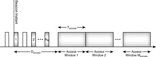
The Master can command the Slaves to unpark in the beacon slots, but a mechanism for Slaves to transmit a request for unparking is also required. The opportunity for parked Slaves to request unparking is provided by a series of access windows which come after the beacon train. The length of the beacon train is given by NBΔB. A series of access windows come after the beacon train. The start of the first access window comes Daccess after
the beacon instant. Usually the access windows come straight after the beacon train, so Daccess = NBΔB.
A series of Maccess access windows come after the beacon train. As Figure 16–8 shows, the access windows start Daccess after the beacon instant. Each window is the same width, and that width is given by T access.
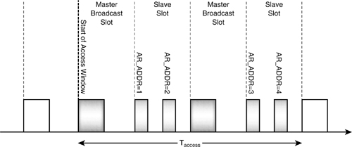
Within an access window, the Master broadcasts transmitting on even slots as usual. Normally Slaves cannot respond to broadcasts, but in the access windows, this is changed. Each Slave in turn is allocated a half slot in the Slave to Master slots. Figure 16–9 shows an access window for a Master with four parked Slaves. The Slave to Master half slots are allocated to each Slave in turn according to their access request addresses. So in the first Slave to Master slot of the access window, the two parked Slaves with access request addresses 1 and 2 can respond. If the Master does not broadcast, the parked Slaves are not allowed to respond, and must wait for the next access slot. For example, if the Master has SCO links, some Slaves’ access request slots will be used by the SCO packets.
Figure 16–8 Access windows for Slave-initiated unparking.
After the Slave has sent an access request, it listens for the Master broadcasting an unpark message with the parked Slave’s Bluetooth device address or parked member address (the parked member address was allocated to the Slave when it was parked and gave up its active member address).
16.4.5 Sleeping through Beacon Slots
A parked Slave can sleep for longer times by sleeping through some beacon trains. The park message carries a parameter telling a Slave the count of beacon trains to wake up at, NBsleep, and a parameter, DBsleep, identifying the first train to wake in. The maximum interval between beacon trains is just under 41 seconds. Theoretically, the Slave could wake after 255 beacon trains, but parked Slaves can use an inaccurate low power oscillator, which means they slowly drift away from the Master’s timing. With the maximum gap between beacon trains and sleeping through the maximum number of slots, a Slave would have over 29 hours between waking up! By this time, it would have hopelessly lost synchronisation with the Master, so parked Slaves should obviously not be set to wake so infrequently.
Figure 16–9 Structure of an access window.
To ensure that parked Slaves do not totally lose synchronisation with the Master, the Master should unpark and repark them occasionally. This is the only way that the Master can be sure that they are still synchronised.
16.4.6 Requesting Park and Unpark
Both Master and Slave can request that a connection be parked. For systems with an HCI, a host can request its module’s LM to park a specific connection using the HCI_Park_Mode command. This command has three parameters:
- Connection_Handle—Identifies the connection to be parked. Only ACL connections can be parked, so this must not be a SCO connection handle.
- Beacon_Max_Interval—The maximum interval between beacon slots.
- Beacon_Min_Interval—The minimum interval between beacon slots.
The Bluetooth module will take some time to process this command, as negotiation between link managers is needed to put a device into Park mode. So the module acknowledges the HCI_Park_Mode command with an HCI_Command_Status event, then when the connection is finally parked, the module sends its host an HCI_Mode_Change event. The host sets minimum and maximum values for beacon interval, so it does not know the actual interval which was negotiated. The HCI_Mode_Change event tells the host what value was negotiated for the beacon interval.
If a host wishes to end Park mode for a connection on its module, it simply sends the HCI_Exit_Park_Mode command. This command only needs one parameter: the connection handle of the connection to be removed from Park mode.
16.4.7 LMP_park_req Message
The LMP_park_req message shown in Figure 16–10 carries more parameters than any other LMP message. The parameters in the park message are as follows:
- Timing control flags—Used to avoid uncertainties in timing caused by clock wrap around.
- DB—Timing of the first beacon slot.
- TB—Interval between beacon trains.
- NB—Number of beacon slots within one beacon train.
- ΔB—Spacing of beacon slots in the beacon train.
- PM_ADDR—Parked member address; identifies the Slave when it is unparked by the Master.
Figure 16–10 The LMP_park_req message.

- AR_ADDR—Access request address used when the Slave requests unparking.
- NBsleep—Number of beacon train at which Slave wakes (it sleeps for NBsleep-1 beacon trains).
- DBsleep—Timing of first beacon train at which the Slave wakes.
- Daccess—Time from beacon instant to first access slot.
- Taccess—Width of access window.
- Nacc-slots—Number of Slave to Master access slots.
- Npoll—Number of slots after access window a Slave listens after requesting unpark.
- Maccess—Number of repetitions of the access window.
- Access scheme—Slave access techniques supported (only polling is defined!).
The LMP_park_req message is used to park a Slave as shown in Figure 16–11. There are two ways that a Slave can be parked:
- The Master requests a Slave to enter Park mode.
- The Slave requests to be put into Park mode.
In version 1.0b there was also an LMP_park message which the Master could use to force a Slave into Park mode. Slaves may not be able to support all possible park parameters, so this message was removed so that the Slave always gets a chance to negotiate Park mode parameters.
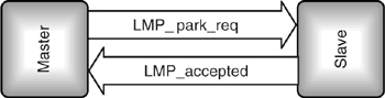
To put a Slave into Park mode a Master sends an LMP_park_req message. If the Slave accepts the request, it replies with an LMP_accepted as shown in Figure 16–11; if it rejects the request, it responds with an LMP_not_accepted as shown in Figure 16–12.
Figure 16–11 LMP message sequence chart for when a Master requests a Slave to enter Park mode and Slave accepts.
If there is no interference, the Slave sends a packet in its response slot and the packet’s acknowledge flag bit tells the Master that the LMP_park_req message had been received. However, the Slave’s response could get lost due to interference on air. This leaves the Master unsure whether the slave has seen the LMP_park_req message, so it re-sends. If the Slave parked immediately, the Master would keep resending until the link timed out. To avoid this the Slave starts a timer of 6 * Tpoll when it sends the LMP_accepted, and parks when it receives a baseband level acknowledgement of the LMP_accepted, or when the timer expires (whichever happens sooner). This keeps the Slave active for long enough for the LMP_park_req and LMP_accepted to be exchanged even in the prescence of some interference.
A Slave requests to be put into Park mode by sending an LMP_park_req as shown in Figure 16–13. The Master can reply with an LMP_not_accepted, or with an LMP_park_req in which case parking proceeds as if the Master requested it (in version1.0b the Master can reply with LMP_park; this is kept for backwards compatibility). The timing parameters in the Slave’s LMP_park_req message are suggestions, and the PM_ADDR and AR_ADDR are ignored entirely: the Master decides the park parameters.
Once the Master has parked Slaves, it can broadcast LMP_unpark messages or data to them in beacon slots. If a Master has more data than will fit in the beacon slots, it can broadcast an LMP_set_broadcast_scan_window message, which tells the parked Slaves to keep listening for an extra window after the beacon slots.
If the Master will regularly have more or less data to send to the Slaves, it can send an LMP_modify_beacon message to change the beacon parameters. Parameters which can be changed by the LMP_modify_beacon message are:
Figure 16–12 LMP message sequence chart for when a Master requests Park mode and Slave does not accept.
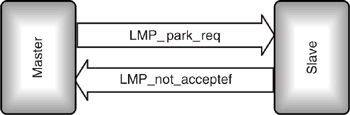
Figure 16–13 LMP message sequence chart for when a Slave requests to enter Park mode.

- DB—Timing of the first beacon slot.
- TB—Interval between beacon trains.
- NB—Number of beacon slots within one beacon train.
- Δ B—Spacing of beacon slots in the beacon train.
- Daccess—Time from beacon instant to first access slot.
- Taccess—Width of access window.
- Nacc-slots—Number of Slave to Master access slots.
- Npoll—Number of slots after access window a Slave listens after requesting Unpark mode.
- Maccess—Number of repetitions of the access window.
- Access scheme—Slave access techniques supported (only polling is defined!).
In version 1.0b there was a potential problem if a Master sent an LMP_park_req and the Slave’s LMP_accepted response got lost, for example, due to interference. In this situation the Master would keep on trying to park the Slave, but the Slave would never reply again because it was already parked. Eventually the link supervision timeout would elapse and the Master would mark the Slave as disconnected, but the Slave could wait forever for an umpark message which would never come!
The Master could of course assume that it had missed the LMP_accepted and assume the Slave was parked, but this just causes problems if the LMP_park_req message was lost. In that case the Master might reuse an active member address from a Slave it thinks is parked, when the Slave is really still active. This leads to two Slaves sharing one active member address.
Version 1.1 of the Bluetooth specification mitigated this problem by adding some timers as follows:
- The Slave attempts to send the LMP_accepted message until it gets a baseband acknowledgement or until 6*Tpoll slots have passed, whichever is sooner.
- The Master is not allowed to reuse the parked Slave's AM_ADDR until 6*Tpoll slots after it has received LMP_accepted.
- If the Master doesn't receive LMP_accepted, then the Slave is detached when the link supervision timeout happens.
These procedures aren't perfect, it is still possible for a Slave’s LMP_accepted message to not get through, so the Slave parks and the Master detaches it. However, because the Slave sends the LMP_accepted for up to 6*Tpoll slots, there is a good chance of the message getting through. It seems that there is no perfect way to guarantee to park a Slave using messages across an unreliable radio link. These procedures are at least a lot more reliable than the 1.0b procedures for parking.
16.4.8 LMP_unpark Message
When Slaves are parked, they give up the Active Member Address (AM_ADDR) and are assigned a Parked Member Address (PM_ADDR). To return a parked Slave to active mode, the Master must send that Slave a new AM_ADDR to use.
Because a parked Slave has no AM_ADDR, it is addressed by its Bluetooth Device Address (BD_ADDR) or by its PM_ADDR. There are two different unpark messages according to which type of address is being used to unpark Slaves: LMP_unpark_PM_ADDR_req and LMP_unpark_BD_ADDR_req. (It is worth noting that the LMP_unpark message changed slightly for version 1.1 of the core Bluetooth specification. In version 1.0b the LMP_unpark_PM_ADDR_req message had 4 bits allocated for the Active Member Address, when in fact the address is only 3 bits long. This caused confusion because manufacturers were unsure where to place the address in the 4 bit field. This caused some interoperability problems which were solved in verson 1.1 by making the field 3 bits long.
Two Slaves can be unparked with a single message simply by placing both their addresses in one unpark message. As Figure 16–14 shows, the sequence of messages and actions is the same whether the parked Slaves are addressed using their PM_ADDRs or BD_ADDRs.
First, an unpark message is sent. This message is broadcast by the Master in a beacon slot. It contains the addresses of the Slaves the Master wishes to unpark (BD_ADDR or PM_ADDR); the message also assigns a new AM_ADDR for each Slave to be unparked.
When the Slaves receive the unpark message, they return to active mode instead of going to sleep as parked Slaves would. To check that the Slaves have received the unpark message, the Master must poll each Slave in turn. Each Slave responds with an LMP_accepted message when it receives the poll.
As the Master is establishing a new active connection, the same timeout is used for unparking Slaves as is used for setting up new connections (newconnectionTO). The Master may continue polling the Slaves until the timeout expires. If the Master does not receive an LMP_accepted, it must assume the unpark failed and wait until the next beacon before trying again to unpark Slaves which did not respond.
16.4.9 Timing Accuracy
When a Slave device returns from Hold mode, it has not received any transmissions for a while, so its clock will have drifted out of synchronisation with the Master’s clock. Normally, a Slave predicts the start of the next transmission from the Master, and opens its correlator for a period of 10 μS on either side of the expected start. On returning from Hold mode, because it can’t accurately predict the start of the Master’s transmission, a Slave must open its correlator across a wider scan window than normal.
Figure 16–14 LMP message sequence charts for when a Master requests Unpark mode.
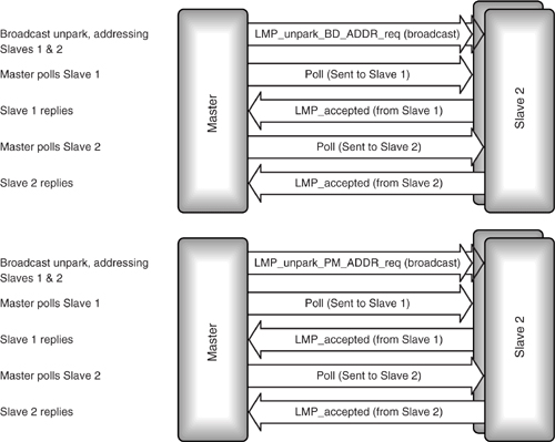
Figure 16–15 shows the difference between the slot timing of an active device and a device returning from Hold mode. The shaded blocks at the top of the diagram show the correlator opening for 10 μS on either side of the estimated start of the receive slot. If the device is a Slave, it recalibrates its estimate of the start of the slot according to when it actually begins to receive.
Figure 16–15 Widening correlation window on return from Hold mode.

The shaded blocks at the bottom of the diagram show the correlator opening on return from Hold mode. The device has not received any packets from the Master during Hold mode, so its estimate of the slot timing has not been corrected for a while.
The device can work out how wide to open the correlators by looking at the accuracy of its own clock and the accuracy of the clock at the other end of the connection. If the accuracy is unknown, the worst case accuracy is used as a default. The worst case allowed by the Bluetooth specification is a clock with jitter of ±10 μS and drift of 250 ppm. This worst case is for a low-power oscillator (see section 16.5); most active devices will perform much better than this.
The accuracy of the clock at the other end of the connection can be retrieved with an LMP_timing_accuracy_req. The remote link manager responds with a LMP_timing_accuracy_res message, which includes parameters for drift and jitter.
Once the device has predicted the width of the uncertainty window, it opens its correlators over the wider window. This may lead to the correlator being opened over more than a slot, as is the case in Figure 16–15. The device continues opening its correlators for the calculated uncertainty window centered on its predicted timing until it receives a packet, or its link supervision timeout elapses.
When slots are missed because the correlator is open over more than a slot, the hop frequency used is the frequency for the receive slot the correlator is centred upon.
Parked and sniffing devices also have to open their correlators wider than usual, because like devices returning from Hold mode, they have not received transmissions from a Master for a while, so their estimate of the beginning of the receive slot will be less accurate.
16.5 Low-Power Oscillator
While a device is not receiving because it is in standby (unconnected) Hold or Park mode, it is allowed to save power by switching off the reference crystal oscillator which drives the Bluetooth clock. Some system is still needed to drive the clock, so instead of the reference oscillator, a low-power oscillator is used.
The reference crystal oscillator has an accuracy of ± 20 ppm; the low-power oscillator (LPO) has a far more relaxed requirement for accuracy at only ±250 ppm. It is the low-power oscillator’s accuracy that sets the default of 250 ppm, which devices must assume when calculating the uncertainty in their prediction of slot boundaries.
16.6 Summary
Many Bluetooth devices will be operated by batteries, so it is important that they do not use more power than necessary.
Some Bluetooth devices such as headsets connected to cellular mobile phones need to respond fast to signals, so ideally they should stay connected all the time to avoid the delay of setting up a connection extending their response time. However, being constantly connected would mean using the radio a lot and would drain the device’s batteries. Blue-tooth provides three low-power modes which extend battery life by reducing activity on a connection. These modes are called Park, Hold, and Sniff.
Park mode provides the greatest opportunities for power saving. The device only wakes up in periodic beacon slots, where it listens for unpark transmissions from the Master. If it is not unparked, it goes back to sleep, switching off its receiver. A special unpark message is used to restore the device to normal activity. Devices which are parked give up their active member addresses, so the unpark messages either use a special parked member address, which is assigned to devices when they are parked, or they can use the device’s Bluetooth Device Address (BD_ADDR). Because a parked device gives up its active member address, one Master can have more than seven devices in Park mode at once (it is the size of the active member address which limits a Master to having a maximum of seven active Slaves).
In Sniff mode, the device wakes up periodically and listens for transmissions, but no special unpark messages are needed to communicate with it. Devices in Sniff mode keep their active member address. Typically, sniffing devices will be active more often than parked devices.
Park and Sniff modes both involve putting devices into a state where they wake up periodically. Conversely, Hold mode just puts a connection in a low-power state for a single period. Connections to Slaves might usefully be put into Hold mode while a Master performs an inquiry or a page, as the Master knows in advance that it will not be able to service the connections for a while.
Many layers of the Bluetooth protocol stack are involved in low-power modes: the baseband/link controller layer alters correlator properties, as after periods of inactivity, the device may lose synchronisation and need to listen for transmissions over a wider window than usual. The link controller layer is also involved with state machines for timing the low-power modes. The link manager provides a variety of messages to configure and negotiate the low-power modes between ends of a connection. HCI provides a set of commands which may be used by a host to configure and control the power-saving capabilities of a module. L2CAP must be aware of low-power modes for its quality of service commitments.
The detailed operation of the power-saving modes can be complex to understand, but for the user of a Bluetooth device, that complexity will be invisible. Properly configured, a Bluetooth device will perform power saving, and the only visibility to the user will be an extended battery life.