
20
Draft Post–Foundation Profiles
When version 1.1 of the Bluetooth specification was released, it contained the same thirteen profiles which were released with version 1.0. These are sometimes called the foundation profiles, and whilst they provided a good start for product manufacturers, they could not cover all possible uses for Bluetooth devices.
To expand the range of profiles available, the Bluetooth SIG has a series of working groups which are developing new profiles. Profiles go through a series of drafts before they are finally adopted into the Bluetooth specification. When profiles reach draft version 0.9, they are released for viewing by all Bluetooth adopters. By this stage the profiles have already undergone extensive review by the Bluetooth Architectural Review Board, Bluetooth Associates, and the Bluetooth Test and Interoperability workgroup, so they are unlikely to change in any significant ways before release.
This chapter covers draft profiles which have been released to adopters, but are not yet formally adopted into the Bluetooth specification. At the time of writing six draft profiles were on release to adopters:
- HID—Human interface devices such as a mouse or keyboard.
- CAR—Hands free phone use.
- Basic Imaging—Basic image transfer.
- Hard Copy Cable Replacement—Replacement of a printer cable with a Bluetooth link.
- Basic Printing—Sending text and XML formatted documents to printers, and printer control.
- PAN—IP over Bluetooth.
Many more profiles are on the way, for details see Chapter 28.
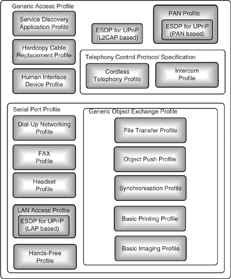
Figure 20–1 shows how the new draft profiles fit within the overall structure of Bluetooth profiles.
Figure 20–1 The new Bluetooth profiles.
20.1 The Human Interface Device Profile
The Human Interface Device (HID) Profile allows devices such as a computer mouse, keyboard, or tracker ball to communicate using a Bluetooth link. The profile uses the HID protocol which is used to communicate with HID devices. The HID protocol originates from the Universal Serial Bus (USB) specification.
Because human interface devices require a fast response, the HID profile is designed to provide low latency communications. This is done using L2CAP Quality of Service (QOS) settings. Many Bluetooth devices do not implement the full QOS functionality, so designers should be aware that response times are likely to suffer if a HID is a slave in a piconet containing other Bluetooth slave devices.
The profile provides a means for the device to describe itself. Some HIDs may require output to the user; for example, a display or force feedback joystick both require output, so the HID profile supports data output as well as input.
Because the HID profile can be used in so many different types of device, it is not possible to say exactly which layers of the Bluetooth protocol stack will be present. Figure 20–2 shows two example stacks. On the left is the type of configuration that might be found on a Host such as a desktop PC with a separate Host Processor and Bluetooth module, so this example includes a Host Controller Interface. On the right is an example from a Human Interface Device; because such devices have limited functionality, all processing can be done within a Bluetooth device’s own processor, so there is no need for a Host Controller Interface.
Figure 20–2 also illustrates the two roles defined by the HID profile: the HID itself and the host which uses the services of the HID. Usually, the host would be the master, but this is not mandatory.
Figure 20–2 Example HID protocol stacks.
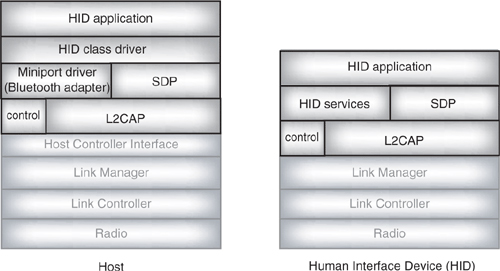
It is likely that many hosts, such as PCs, will already have USB HID drivers. These can be used with Bluetooth devices by the addition of an adapter driver, sometimes called a miniport driver. The adapter driver handles the Bluetooth specific connection management and passes HID protocol information up to the USB HID driver.
The HID profile aims to allow devices to run for three months on three AAA or two AA alkaline batteries. To achieve this the host should allow HIDs to initiate sniff and park
modes, although hold mode is optional. If the host wants to send data to a parked or sniffing slave, it simply sends an unsniff or unpark request. Designers should be aware that putting a device in park or sniff mode will add a delay to communications as the unpark or unsniff request goes out in one beacon, then the response comes back in the next beacon, then data can be transferred on the next host poll.
20.1.1 HID Descriptors
Information about a HID is stored in descriptors. These are just records held in segments of memory. (In production devices the descriptors would usually be stored in ROM because it is a very cheap form of memory.) The HID profile uses four types of descriptor:
- Interface Descriptor—Identifies the class, or type, of the device. The class is used to identify the correct HID class driver which can communicate with the HID.
- Device Descriptor—Gives the types and sizes of descriptors other than the interface descriptor.
- Report Descriptor—Defines items which describe an output such as a position or button state. The report descriptor tells the HID class driver about the size and composition of data reports from a particular item.
- Physical Descriptor—Optional information on parts of the human body used to activate the controls on a HID.
20.1.2 L2CAP Interrupt and Control Channels
There are two different types of reports: HID reports carrying input or output data on user interactions requiring a fast response and feature reports carrying background control information which are not so time critical. HID reports and feature reports are carried on different L2CAP channels, each with its own QOS and each identified by its own protocol service multiplexor (PSM).
HID reports can be input reports carrying data from HID to host, or output reports carrying data from host to HID. One example of an input report is a key press report from a keyboard; an example of an output report is a report to trigger force feedback effects in a joystick. To achieve the best response time, HID reports should be carried on an L2CAP channel which can be set to guaranteed quality of service, this is called the interrupt channel or HID_Interrupt. There is no point using a guaranteed channel if there is no data to transfer, and it is possible that a HID will only send data in one direction. If the HID doesn’t declare any data input reports, then the input direction has QOS set to No Traffic. Similarly, if the HID declares no output reports, then the output direction has QOS set to No Traffic. If a device declares data input reports and data output reports, then they are both carried on the same L2CAP channel HID_Interrupt, in this case the latency specified in the L2CA_ConfigReq primitive will affect data flow in both directions, so it should be set to satisfy the direction needing the lowest latency.
Feature reports carry initialisation information and control data for the application. For example, they might carry information on device options or device state or coordinate scaling parameters. The background control data carried in feature reports does not require fast responses. In order to allow HID reports to take priority over feature reports, the feature reports are carried on an L2CAP channel with best effort quality of service. The channel used for feature reports is called the Control channel or HID_Control.
It is possible that one HID might implement more than one function, for instance, a combination keypad and joystick. Such multifunction devices appear to be two different HIDs both on the same Bluetooth link. The two HIDs can share the same control and Interrupt channels because the HID protocol uses report IDs to sort out which HID a particular report is coming from.
20.1.3 Configuring an HID Device
A cabled HID is configured across its wired connection, but for Bluetooth HIDs the device must be discovered and configured across the Bluetooth link. The HID profile recommends that HIDs should use limited discoverable mode. The HID would enter discoverable mode by human interaction. This is needed for two reasons: first, HIDs are likely to be battery powered and constant inquiry scans would drain their batteries; second, entering discoverable mode only at the push of a button helps to make the HID more secure by hiding it from inquiries most of the time.
Once the HID is in discoverable mode the host can find it, establish a link, and the HID passes its HID descriptors to the host. The HID profile defines the same default PIN code as the LAN Access Profile: a single byte set to zero.
There is a curious problem when initiating an authenticated link with a Bluetooth keyboard: the host hasn’t got a keyboard to enter the PIN on! The solution is for the host to generate a random PIN and display it. The number displayed is then entered on the keyboard, in this way both ends of the link get the same PIN and authentication can proceed.
The profile recommends that authentication and encryption are used with HIDs, but neither is mandatory.
The HID_Control channel is established first, then the HID_Interrupt channel, but because L2CAP configuration can take a while, both channels may be being configured at the same time.
It is usual for PC hosts to need keyboard interaction as the system is booting, so keyboard support has to be built into the BIOS. The HID profile suggests that for PC hosts which do not have BIOS support, the keyboard could be provided with a USB/PS2 adapter which would allow the keyboard to be used as a wired device whilst the PC was booting.
20.1.4 Virtual Cables—Reconnecting to HIDs
When a HID has been connected with a host, if both sides want to keep a one to one link, then they have the option of marking both sides of the link as virtually cabled. HIDs which want to use virtual cables set HIDVirtualCable to TRUE in their Service Discovery Records. A virtual cable can only connect one HID to one host. For example, a virtually cabled remote control can’t be used to switch two devices simultaneously (as could be done with an infrared remote control). If another host tries to connect to a virtually cabled HID, the second host will be refused.
If a virtually cabled connection is dropped, automatic reconnection will be attempted. Since HID and host have to agree on which side will do the paging, the HID device has a HIDReconnectInitiate service record. If this is true, the HID will initiate reconnection by paging; if it is false the HID will page scan and wait for the host to initiate reconnection. If the HID initiates the connection to the host, a master/slave switch is used to avoid the HID remaining as the master of the link.
A HID connection might be lost for many reasons: HID and host move out of one another’s radio range, either device is reset, or perhaps there is a prolonged burst of interference. The host will try to reconnect for 30 seconds, after this time it is allowed to time out, though of course the user can always restart the connection process.
Virtually cabled devices store information to allow reconnection. To disconnect the virtual cable and connect the HID to another host the user must intervene. For instance, the user could press a button on the HID before it is connected to another host. The HID would then try to inform its virtually cabled host that the virtual cable was being unplugged.
20.1.5 HID Protocol
The HID profile provides a Bluetooth HID (BT-HID) protocol for communications between host and HID. This protocol defines a set of services and provides support for transferring messages belonging to a further two protocols: Boot Protocol and Report protocol.
One obvious question is why BT-HID implements both report and boot protocol: is this just unnecessary complication? The reason is that devices such as PCs may need to communicate with mice and keyboards during bootup. Having a simpler boot protocol makes it easier to implement a simple HID driver at the BIOS level, allowing input from HIDs during bootup. However, because the boot protocol is simple, it only allows limited input reports: in the case of keyboards, 103 keys as provided on PC-AT keyboards, and in the case of mice a simple three button mouse with movement in two directions.
Report Protocol uses a parser to interpret the Report Descriptor which is stored in the HID’s SDP service record. This allows more complex information to be sent, allowing extended functionality in HIDs. The Report protocol parser is too complex for most manufacturers to want to implement it at BIOS level.
Both protocols use transactions: a transaction consists of a request from the host to the HID followed by a data or handshake payload from the HID to the host. Some messages are just used by boot protocol, some by report protocol, and some are used by both. The sections on boot and report protocol below describe how and when the messages are used.
In order to distinguish between the different HID message types, all HID messages begin with a single byte header called the BT-HID Transaction Header (THdr). Figure 20–3 illustrates the format of the header: just four bits to identify the type of transaction and four bits of parameter. The meaning of the parameter bits depends upon the Transaction Type. The possible values of the Transaction Type are:
Figure 20–3 BT-HID Transaction Header.

- 0x0 - HANDSHAKE—Acknowledges a request when no data needs to be sent.
- 0x1 - HID_CONTROL—Requests a major state change.
- 0x2 - 0x3—Reserved.
- 0x4 - GET_REPORT—Gets report data.
- 0x5 - SET_REPORT—Sets report data.
- 0x6 - GET_PROTOCOL—Retrieves the current protocol being used.
- 0x7 - SET_PROTOCOL—Sets the protocol to use.
- 0x8 - GET_IDLE—Retrieves idle rate of a device.
- 0x9 - SET_IDLE—Sets preferred idle rate of a device.
- 0xA - DATA—Carries payload data.
- 0xB - DATC—Carries continuation of data which would not fit in a DATA report.
- 0xC-0xF—Reserved.
If any GET request is received with no errors, the HID replies with a DATA pay-load. If the data requested doesn’t fit in one DATA payload, then data continuation DATC payloads are used until all data has been sent.
If any SET request is received, the device responds with a HANDSHAKE. The HANDSHAKE message is also used to reply to any GET request with an error.
20.1.6 Boot Protocol
Version 0.9 of the HID protocol defines boot protocol support for keyboards and mice. As mentioned above, the boot protocol does not need a parser because it uses predefined Report Descriptors which are defined in the HID specification.
Not all HIDs will support Boot protocol, so Boot protocol support is indicated in the FHS class of device, or using the HIDBootDevice attribute in SDP.
In both boot mode and report mode GET_REPORT is used to poll a device for data, and SET_REPORT is used to send data to a device. If the data does not fit in one payload, data continuation (DATC) messages are used to send remaining data.
A multifunction device might implement both mouse and keyboard functionality—for example, a gamepad might incorporate a joystick which provided directional information and a range of buttons which acted like a keypad. The reports from the mouse function must be separated from the reports from the keyboard function, but both are coming across the same Bluetooth link. The HID profile identifies the type of HID a report comes from by starting each report with a single byte Report ID. The Report IDs defined in version 0.9 of the HID specification are:
- 0—Reserved.
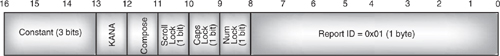
- 1—Keyboard. Input report size is 9 bytes as shown in Figure 20–4, output size is 2 bytes as shown in Figure 20–5.
Figure 20–4 BT-HID keyboard input report.
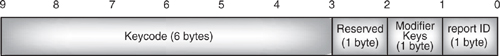
Figure 20–5 BT-HID keyboard output report.
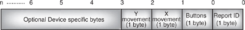
- 2—Mouse. Report size is 4 bytes as shown in Figure 20–6.
- 3–255—Reserved.
A keyboard requires an output report as well as an input report because the keyboard must receive modifier keys. Modifier keys are keys such as CTRL, ALT, SHIFT, which are pressed in combination with another key to change its meaning. Since several modifier keys can be pressed at once, the keyboard output report is a bit field; bits are simply set to one if a key is pressed and zero otherwise.
After the report ID comes a report which uses the format defined in the HID specification. Because of the report ID, the HID reports are 1 byte longer than the standard records, giving a 9 byte keyboard report and 4 byte mouse report.
In report protocol the report ID can be omitted from devices which do not support multiple functions (it is possible to tell from service records whether a device is single function or multifunction). In boot protocol the report ID is always used because it is simpler to implement a fixed format than one with optional elements.
It is possible to add extra data onto the end of the reports. In boot mode the host will ignore the extra data, but it is useful to be able to send it, as it means a HID can send extra data related to functions described in the report mode descriptor. By allowing a HID to do this, the specification allows it to send identical reports in boot mode and report mode, thus allowing the HID design to be simpler.
In addition to sending data reports, all devices which implement boot protocol must support two transactions:
Figure 20–6 BT-HID mouse report.
- GET_PROTOCOL—Gets the current protocol on the HID; the reply is a byte of data set to 0 for report protocol and 1 for boot protocol.
- SET_PROTOCOL—Switches a device between boot protocol and report protocol.
Keyboards must also support two extra transactions to manage idle rate. The idle rate reports how often a keyboard sends key down information to the host. The two messages used to manage idle rate are:
- GET_IDLE—Gets the current state of the HID; the reply is a byte of data giving the idle rate.
- SET_IDLE—Used to change the idle rate in line with user preferences.
A zero idle rate means a keyboard only reports when a key is pressed. Non-zero values give the time between reports in units of 4 milliseconds. Of course, the reports are limited by the QOS of the L2CAP HID_Interrupt channel, so if the idle rate is less than the channel latency, the reports will be generated at the Interrupt channel latency rate.
20.1.7 Report Protocol
Report mode can use more complex formats in its reports, allowing more functionality to be implemented in devices. To do this report mode requires a parser. An extra message: HID_CONTROL is supported to handle more complex functions.
The HID_CONTROL message requests a major state change in a HID. It carries a parameter to identify the new state. Possible values for the parameter are:
- 0x0—No Operation (NOP).
- 0x1—Hard Reset: Restart device including Power On Self Test (POST) reinitialisation and restart normal operation.
- 0x2—Soft Reset: Initialise all variables and restart normal operation.
- 0x3—Suspend: Go to reduced power mode.
- 0x4—Exit Suspend.
- 0x5—0xF—Reserved.
The Suspend command allows a host to inform the HID when reduced response times are acceptable. This might be because the Bluetooth link is being used for high bandwidth data transfer, so normal QOS is not possible, or it might be because inactivity has triggered a low power standby state in the host. This allows the HID to use park or sniff mode; of course, it may also choose to perform other power saving operations, such as switching off LEDs or lowering the key scan frequency.
Low power modes are crucial if HID devices are to achieve the three month battery life target the HID profile sets. Therefore, the host should use the HID_CONTROL message to allow suspend whenever higher latency communications are acceptable.
20.2 The Hands-Free Profile
The Hands-Free Profile (HFP) defines functionality which allows a mobile phone to be used with a hands-free device. It differs from the headset profile by providing remote control of the phone as well as a voice connection. The hands-free profile was developed by the Bluetooth SIG’s Car working group, so not surprisingly the main usage model mentioned in the profile is using a phone with a hands-free device installed in a car.
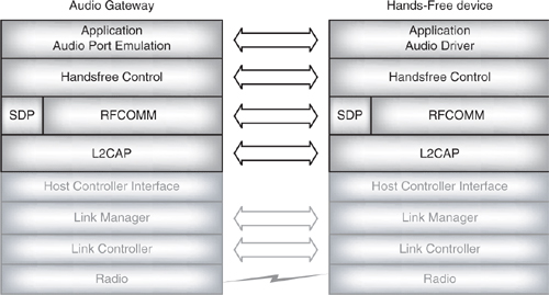
As Figure 20–1 shows, the hands-free profile relies upon the Serial Port Profile and the Generic Access Profile. Figure 20–6 shows how the hands-free control relies upon RFCOMM for data transfer. The protocol stack looks similar to the stack used for the headset profile; in fact, the signalling is AT command based, as is the signalling in the headset profile.
The Audio Gateway (AG) is the device which is the gateway for audio coming from a network. A typical Audio Gateway device is a cellular phone. The Hands-Free Unit (HF) acts as a remote audio input and output for the Audio Gateway and also provides some control of the Audio Gateway. An example is a hands-free unit installed in a car.
The Hands-Free Profile supports service level connections, which are RFCOMM connections used for control and status updates. It also supports a single audio connection which provides bidirectional (duplex) audio across a SCO link using the CVSD codec. CVSD was chosen because it is the most error-tolerant of the codecs supported by the Bluetooth Core specification.
Figure 20–7 Hands-free protocol stack.
20.2.1 Establishing a Service Level Connection
A service level connection is used to transfer control information between Hands-Free and Audio Gateway. Figure 20–8 shows an example of establishing an audio gateway. In this example the connection is initiated by the user interacting with the Hands-Free device, but it is also possible for the connection to be initiated by user interaction at the Audio Gateway side, or by an automatic internal event in either device.
Figure 20–8 Establishing a service level connection.
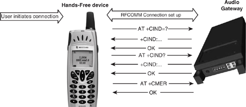
The first stage is to establish an RFCOMM connection, initialising RFCOMM if necessary. In order to do this, the initiating device may need to establish an SDP session to retrieve service records giving the parameters needed to set up the RFCOMM connection.
The Hands-Free profile passes status information from the Audio Gateway to the Hands-Free as indicators. Two indicators are supported:
- service—Gives service availability: 0=no service, 1 = service is present.
- call—Call status indicator: 0 = no call in progress, 1 = a call is in progress.
The Hands-Free retrieves information on which indicators are supported from the Audio Gateway using an AT+CIND=? command. The gateway replies with a +CIND giving the call indicators and an OK confirming successful completion of the command.
Once the Hands-Free knows which indicators are supported, it can request the current status of the indicators in the Audio Gateway using an AT+CIND? command. The Audio gateway replies with a +CIND giving the status of the indicators and an OK confirming successful completion of the command.
The Hands-Free requests the Audio Gateway to enable status update using the AT+CMER=… command. This can be used to set indicator events reporting, that is to say reporting when there is an event affecting service availability or whether there is a call in progress. There are only two permitted parameter strings for this command:
- AT+CMER=3,0,0,1 switches on indicator events reporting.
- AT+CMER=3,0,0,0 switches off indicator events reporting.
The Audio gateway replies with OK to confirm successful completion of the command.
Once the indicator events reporting has been set up, the service level connection has been established and the Hands-Free is ready to be used with the Audio Gateway.
If there is no subsequent activity, and if the Hands-Free and Audio Gateway support park mode, the connection is parked. Either side can request park mode. When the connection enters park mode, the L2CAP and RFCOMM data link channels are not released, so that service can be made available as quickly as possible when it is needed. Either side can request an unpark and return the connection to active mode as a result of an internal event (such as a timer expiry) or as a result of user interaction. If park mode is not supported, then the link remains active, as it is required for status updates.
20.2.2 Transferring Status Information
The previous section explained how the AT+CMER command is used to enable or disable indicator events reporting.
Once Indicator events reporting is enabled, the Audio Gateway will send the Hands-Free a +CIEV result code whenever its current call status changes. The Hands-Free uses the information from the +CIEV result code to generate a “call process ongoing” or “no call present” indication for the user.
The CIEV result code is sent whenever a call is answered, terminated, or dialed.
20.2.3 Handling Calls
When the Audio Gateway receives an incoming call from the network, it sends a series of unsolicited RING alerts to the Hand-Free device. Optionally, it may send an in-band ringing tone using the audio connection. The Audio Gateway may also optionally use the CLIP command to send a Calling Line Identification Notification.
The RING alerts are repeated as long as an incoming call is still present and the Hands-Free has neither accepted nor rejected the call. Figure 20–9 shows an incoming call being accepted after two repeats of the RING.
Figure 20–9 Answering an incoming call.

If the user accepts the call, the Hands-Free sends an ATA command, the Audio Gateway replies with OK to confirm successful completion of the command, and the Audio Gateway sends a +CIEV event notification to indicate the call status has changed to call active.
If the user rejects the call, then instead of the +ATA command, the Hand-Free sends an AT+CHUP hangup command. The Audio Gateway still replies with OK to confirm successful completion of the command and still sends a +CIEV to indicate the call status has changed, but this time the new status is “no call”.
Figure 20–9 shows a call being answered when there is in band ringing. If in-band ringing is not used, then the setup of the audio connection can be delayed until after the +CIEV event is sent. This avoids setting up an audio connection before it is known whether the call will be accepted or rejected.
Call termination is shown in Figure 20–10. First the user intervenes to terminate the call. This causes the hands-free device to send the same +CHUP command which is used to reject an incoming call. The Audio Gateway drops the call and responds with an OK to confirm that the command was successful. Finally, the Audio Gateway sends a +CIEV event to notify the new call status, which is “no call”.
Figure 20–10 Terminating a call.
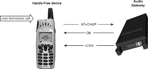
It is possible that a call will be terminated from the Audio Gateway end—for instance, if the call is dropped due to network problems. In this case the Audio Gateway simply sends a +CIEV event notification with a call status of “no call”. This informs the Hands-Free that the call is no longer present.
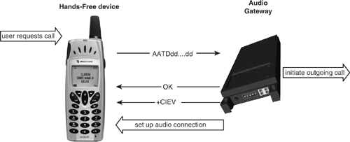
The Hands-Free can make an outgoing call simply by providing the audio gateway with the number to call. Figure 20–11 shows how this is done using an ATDdd…dd command. The dd…dd part of the command is the digits of the number to be dialed. The Audio Gateway begins setting up the outgoing call, then sends an OK back to the Hands-Free to confirm that the dial command has been successful. When the call goes through, the Audio Gateway notifies the Hands-Free with a +CIEV event using a call status of “call active”. If there isn’t already an audio connection between the Hands-Free and the Audio Gateway, then the Audio Gateway sets one up at this point so that it can carry the call.
Figure 20–11 Hands-Free makes an outgoing call.
Similar procedures can be used to dial from the Audio Gateway’s memory or to re-dial the last number called. To dial from memory the ATDdd….dd command is replaced with a ATD>nnn command where nnn identifies the memory location on the Audio Gateway holding the number to dial. The rest of the procedure is the same as when dialing using the ATDdd…dd command.
To redial the last number called, a special extension to the AT command set has been defined by the Hands-Free Profile. This is the AT+BLDN command. The Hands-Free sends AT+BLDN in place of the ATDdd…dd command, and the Audio Gateway retrieves the last number called from memory. The rest of the procedure is the same as when dialing using the ATDdd…dd command.
20.2.4 Call Waiting and Call Holding
The Hands-Free Profile supports two types of call information notifications which the Audio Gateway can send to the Hands-Free to give the Hands-Free more information whilst a call is in progress. These are Call waiting and caller line identification.
Notifications must be enabled before they will be used. The Hands-Free sends the AT+CCWA command to enable call waiting notification, the Audio Gateway replies with OK to indicate that call waiting notification has successfully been enabled. Once Call Waiting notification is enabled, the Audio Gateway will send a +CCWA unsolicited result code to the Hands-Free whenever an incoming call is waiting whilst a call is in progress. Some Audio Gateways will only be able to handle one call at a time, and so they will not be able to detect an incoming call whilst another call is active. These Audio Gateways will be unable to support Call Waiting notification.
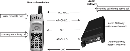
If the user wants to switch to a call which is waiting, they will have to hold the existing call. When the user requests hold, the Hands-Free sends a AT+CHLD command to the Audio Gateway, the Gateway replies with OK, and switches to the waiting call. The AT+CHLD command can then be used (with different parameters from the first time) to create a three way call. Of course, a three way call can only be established if the Audio Gateway supports this feature. The messages exchanged when a Hands-Free wishes to hold a call and then initiate a multiparty call are shown in Figure 20–12.
Figure 20–12 Hands-Free holds a call then makes a multiparty call.
20.2.5 Caller Line Identification
The number of an incoming call can be sent from the Audio Gateway to the Hands-Free, so that the user can be informed on which number is calling. To enable this feature the Hands-Free sends an AT+CLIP command to the Audio Gateway, the Audio Gateway replies with OK to confirm that the command has been successful. The next time an incoming call is received, the Audio Gateway sends a +CLIP Calling Line Identification notification to the Hands-Free.
The Caller Line Identification feature remains enabled until it is disabled using another +CLIP command from the Hands-Free or until the Service Level Connection between the Audio Gateway and Hands-Free is dropped.
20.2.6 Controlling Audio Functions and DTMF Tones
A variety of commands are available to control the audio functions of the Audio Gateway: the Echo Cancelling and Noise Reduction can be enabled or disabled, the volume can be remotely controlled, and DTMF tones can be generated.
If the Audio Gateway supports Echo Cancelling and Noise Reduction, these features are enabled by default. They can be switched on and off using the AT+NREC command. The settings remain in effect until changed again with the AT+NREC command, or until the service level connection is dropped.
The Audio Gateway can control the Hands-Free’s microphone gain by sending a +VGM to the Hands-Free. Similarly, the Audio Gateway can control the speaker gain by sending a +VGS to the Hands-Free. The gains are given on a scale from 0 to 15, so, for instance, +VGS:15 sets maximum volume on the speaker, and +VGM:0 sets minimum gain on the microphone.
The Hands-Free may store volume levels so that they don’t have to be set every time a connection is established. If the Hands-Free does this, then when a new connection is established, it tells the Audio Gateway what levels it has retrieved by using AT+VGS and AT+VGM commands.
If the user manually changes the speaker gain, the Hands-Free informs the Audio Gateway with an AT+VGS command, the Audio Gateway replies with the usual OK response. Similarly, if the microphone gain is changed by the user, the Hands-Free sends the Audio Gateway an AT+VGM command, and again receives an OK confirming it has been received.
DTMF tones can only be generated whilst there is an active call. The Hands-Free sends the Audio Gateway an AT+VTS command to generate a DTMF tone. The tone to generate is carried as a parameter following the AT+VTS command.
20.2.7 Voice Recognition
If the Audio Gateway supports voice recognition, it must support the AT+BVRA command. This is an extension to the AT command set defined by the Hands-Free profile and is used to switch voice recognition features on and off. The Audio Gateway confirms success of the command by replying with an OK.
Obviously, for voice recognition to work, there must be an audio link active between the Audio Gateway and the Hands-Free. So if the AT+BVRA command enables voice recognition when there isn’t an audio link present, the Audio Gateway sets up an Audio link after sending the OK response.
The AT+BVRA command remains in effect until another AT+BVRA command is sent, the service level connection is dropped, or the LMP link is dropped.
Hands-Free devices which support voice recognition can attach a phone number to a voice tag. This provides much more user-friendly interaction with the Audio Gateway—for instance, the user can say “Fred” instead of reading out Fred’s number.
The Audio Gateway stores the last voice tag it recognised in memory. If the Hands-Free wants to access this information, it sends the Audio Gateway an AT+BINP=1 command. This is an extension to the AT command set defined by the Hands-Free profile. The parameter 1 tells the Audio Gateway that the Hands-Free wants the number associated with the last voice tag recognised. The Audio Gateway responds with a +BINP response with a data parameter containing the phone number associated with the voice tag.
20.2.8 Summary of AT Commands
The Hands-Free profile uses AT commands derived from the GSM 07.07 standard. The previous sections have described how these commands are used in the profile, for reference they are also summarised here:
- ATA—Call Answer.
- ATDdddddd…—Place a call (dial) using the supplied digits ddddd for the called number.
- ATD>nnnnn—Place a call (dial) using a number from memory.
- Error—Indicates a syntax, format, or procedure error.
- OK—Acknowledges execution of a command.
- RING—Indicates an incoming call.
- AT+CCWA—Call waiting notification.
- +CCWA—Unsolicited result code for call waiting notification.
- AT+CHLD—Call hold and multiparty management.
- AT+CHUP—Hangup.
- AT+CIND—Indicator update, used to get status information.
- +CLIP—Unsolicited result code for Calling Line Identification Notification.
- AT+CMER—Activate event reporting.
- +CIEV—Unsolicited result code for indicator events reporting.
- AT+VTS—DTMF tone generation.
The Hands-Free profile also defines the following new AT commands:
- AT+BINP—Request specified data from Audio Gateway.
- AT+BLDN—Redial the last number dialed.
- AT+BVRA—Enable or disable voice recognition.
- +BVRA—Unsolicited result code for autonomous voice recognition disable by Audio Gateway.
- AT+NREC—Disable echo cancelling and noise reduction functions.
- AT+VGM—Report microphone gain level.
- +VGM—Unsolicited result code giving microphone gain.
- AT+VGS—Report speaker gain level.
- +VGS—Unsolicited result code giving speaker gain.
The extra commands defined by the Hands-Free profile use the standard GSM 07.07 format and syntax rules.
20.3 The Basic Imaging Profile
The Basic Imaging Profile (BIP) defines functionality which allows a device such as a camera to transfer still images in a predefined format across a Bluetooth link.
Of course, images could be transferred as files using the File Transfer Profile, the Basic Image Profile adds the ability to negotiate image size and format. The Basic Imaging Profile was created by the Bluetooth SIG imaging working group.
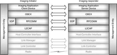
As Figure 20–1 shows, the Basic Imaging Profile relies upon the Generic Object Exchange Profile and the Generic Access Profile. Figure 20–13 shows how the Basic Imaging Profile relies upon OBEX for data transfer and follows the OBEX client/server architecture with the Imaging initiator acting as the client device and the imaging responder taking the server role. An example of such roles might be a laptop PC acting as an initiator requesting image files from a digital camera which would act as responder. Many of the Bluetooth profiles have ignored much of the control and coordination of the Bluetooth layers, so it is worth noting that the Basic Imaging Profile explicitly states that there should be a management entity (ME) coordinating initialisation and managing the link state. This entity is shown in Figure 20–13 stretching across all the layers of the protocol stack.
Figure 20–13 Basic Imaging protocol stack.
There are no fixed rules as to which device is master and which is slave, although to act as the Imaging Responder, a device must be configured in advance. Configuration as an Imaging Responder is done by entering Bluetooth imaging mode. This sets the imaging responder as connectable and allows it to receive commands from Imaging initiators.
The Basic Imaging Profile recommends that Bluetooth imaging mode should be set by user interaction, though it does not forbid entering the mode automatically.
20.3.1 Features and Capabilities
All devices supporting the Basic Imaging Profile must be able to exchange basic imaging data; this is called Generic Imaging capability. Supporting generic imaging implies supporting either Image Push or Image Pull.
There are three extra optional capabilities. These are only required for particular types of device, so they are not required for all devices supporting the Basic Imaging Profile:
- Bluetooth Controlled Capturing—Controlling the capture of an image.
- Bluetooth Controlled Printing—Controlling the printing of images.
- Bluetooth Controlled Display—Controlling the display of images.
Generic Imaging and the three extra capabilities can be combined to enable the Basic Imaging Profile to support six features:
- Image Push—Push images to a responder.
- Image Pull—Browse images stored in a responder and download images on request.
- Advanced Image Printing—Send print jobs to an imaging responder which is a printer.
- Automatic Archive—Triggers an Imaging responder to download some or all images stored on the imaging initiator.
- Remote Camera—For an imaging responder which allows image capture, such as a digital camera; allows the imaging initiator to monitor thumbnail images from the imaging responder and to trigger the shutter on the imaging responder.
- Remote Display—for an imaging responder with display capability, allows the user to push images for display, and to control the display sequence.
20.3.1 Image Push
The Image Push feature allows an Imaging Initiator to send images to an Imaging Responder. It uses four functions:
- GetCapabilities—This is optional and allows the Imaging Initiator to find out the image encodings and sizes which are supported by the Imaging Responder.
- PutImage—Pushes an image from Imaging Initiator to Imaging Responder.
- PutLinkedThumbnail—This is used by an Imaging Responder immediately after it has pushed an image to the Imaging Initiator; PutLinkedThumbnail pushes a thumbnail version of the image.
- PutLinkedAttachment—This is used by an Imaging Responder immediately after it has pushed an image to the Imaging Initiator, PutLinkedAttachment pushes an attachment related to the image.
Figure 20–14 shows an example sequence of messages exchanged during use of the Image Push feature. The functions are carried in OBEX Get and Put messages.
First the Imaging Initiator establishes a connection to the Image Push service. This will involve using SDP to find the services attributes and establishing all the underlying connections through the layers of the Bluetooth protocol stack shown in Figure 20–13.
The Imaging Initiator optionally sends a GetCapabilities request in an OBEX Get Request. The Imaging Responder replies with a Success Get Response containing its ImagingCapabilities.
The Imaging Initiator then pushes images to the Imaging responder using Put Requests. After each Put Request, the Imaging Responder replies with a PutResponse.
The example shown in Figure 20–14 is based on Annex A of the Basic Imaging Profile. It shows two images being pushed. The ImagingResponder replies to the first PutImage with a Success Response. After the second image has been pushed, the Imaging responder requests extra content by replying with a Put response: Partial Content. The Imaging Initiator responds by sending extra content associated with the image in two further OBEX Put requests. The first Put request sends a thumbnail using PutLinkedThumb-nail. The second Put request sends an attachment using PutLinkedAttachment.
Figure 20–14 Message sequence chart for Image Push.
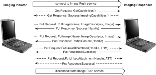
This example shows just two images being transferred; however, the session can continue as long as the Imaging initiator wishes to keep requesting content from the Imaging Responder. Once the Imaging Initiator has finished requesting content it will disconnect from the Image Push Service.
20.3.2 Image Pull
The Image Pull feature allows an Image Initiator to browse images stored in an Image Responder and download images on request.
It uses the same GetCapabilities function as the Image Push feature, but also uses six more functions:
- GetImagesList—Gets a list of handles for images on the Imaging Responder along with file information such as creation and modification dates.
- GetImageProperties—Gets image formats and encodings information which are available for an image.
- GetImage—Gets an image from the Imaging responder in a specified format and encoding.
- GetLinkedThumbnail—Gets a thumbnail sized image from the Imaging responder.
- GetLinkedAttachment—Gets an attachment related to an image from the Imaging Responder.
- DeleteImage—Deletes a specified image from the Imaging Responder.
Figure 20–15 shows an example sequence of messages exchanged during use of the Image Pull feature. As with all Basic Imaging functions, the messages are carried in OBEX Put and Get messages.
First the Imaging Initiator establishes a connection to the Image Pull service. This will involve using SDP to find the services attributes, and establishing all the underlying connections through the layers of the Bluetooth protocol stack shown in Figure 20–13.
The Imaging Initiator sends a GetImageList request in an OBEX Get request. The Imaging Responder replies with a Success Get Response containing handles for images which it has available for retrieval.
The Imaging Initiator can now begin retrieving images. Optionally, it may send a GetImageProperty request for each image to find out what formats and encodings are supported for images. The GetImageRequest carries a Handle identifying a particular image. The Imaging Responder replies to each GetImageRequest with a Success response containing the image’s properties.
The Imaging initiator may also optionally retrieve thumbnails using an OBEX Get request containing a GetLinkedThumbnail. The GetLinkedThumbnail carries a Handle identifying a particular image. The Imaging Responder replies with a Success response carrying the thumbnail image.
Figure 20–15 Message sequence chart for Image Pull.
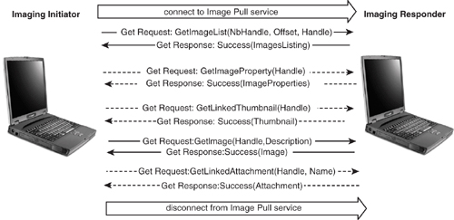
To retrieve the images themselves, a GetImage request is sent. This has a Handle identifying the image and an image description specifying the format and encoding to be used. The Imaging Responder sends the image back in a Success response.
Optionally, the Imaging Initiator can retrieve an attachment related to the image. To do this it sends a Get Request containing GetLinkedAttachment. A handle identifies the image the attachment is related to, and a name identifies the file name of the attachment (this enables multiple attachments related to one image to be retrieved).
The example shown in Figure 20–15 is based on Annex A of the Basic Imaging Profile. It shows just one thumbnail, image and attachment being retrieved; however, the Imaging Initiator can retrieve as many images, thumbnails, and attachments as are available. Once the Imaging Initiator has finished retrieving content, it disconnects from the Image Pull Service.
20.3.3 Advanced Image Printing
The Advanced Image Printing feature is used to send print jobs to an Imaging Responder which is a printer. It uses the same GetCapabilities function which is used by other features. In the case of an Image Responder which is a printer, the GetCapabilities function retrieves the printing capabilities. The Advanced Image Printing feature also uses three more functions:
- GetPartial Image—This is used by the Imaging Responder to retrieve images needed for a print job.
- StartPrint—This is used by an Imaging Initiator to request an Imaging Responder to start printing.
- GetStatus—This is used by an Imaging Initiator to monitor a secondary connection which may be used to retrieve information required for a print job.
Figure 20–16 shows an example sequence of messages exchanged during use of the Advanced Image Printing feature. The functions are carried in OBEX Get and Put messages. This figure shows two instances of the Imaging Initiator. These are both the same device, but the Imaging initiator has two roles: as Primary Client and as Secondary Server. To make the message flows to each role easier to distinguish, the same Imaging Initiator has been shown twice on the diagram, once for each role it takes.
First the Imaging Initiator establishes a connection to the Advanced Image Printing service. This will involve using SDP to find the service’s attributes and establishing all the underlying connections through the layers of the Bluetooth protocol stack shown in Figure 20–13. The initial connection is made by the Imaging Initiator in its Primary Client role.
Optionally, the Imaging Initiator may send a GetCapabilities Request to find the Capabilities of the Imaging Responder.
The Imaging Initiator will then use an OBEX Put message to send a StartPrint message to the Imaging Responder. If this successfully starts a print job, the Imaging Responder replies with Success.
The print job will include information about images to be printed. To retrieve these images, the Imaging Responder opens a second channel to the Imaging Initiator. This channel connects to the Referenced Objects Service.
Usually the Imaging responder acts as a server, but in order to retrieve the images it needs to print, it must act as a client and request the images from the Imaging Initiator. It does this with OBEX Get requests containing GetPartialImage messages. The Imaging Initiator acts as a client on this secondary connection and supplies the images requested in Success responses.
Whilst images are being retrieved, the Imaging Initiator can check on the status of the job by sending GetStatus messages to the Imaging Responder on the primary channel, as long as images are being retrieved the Imaging Responder will reply with a Continue response.
Figure 20–16 Message sequence chart for Advanced Image Printing.
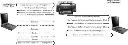
When the final image has been retrieved, the Imaging Responder disconnects from the Referenced Objects service. If the Imaging Initiator sends the Imaging Responder a status message after disconnection of the secondary channel, it will get a Success response back. This signals that the job has finished and allows the Imaging Initiator to disconnect from the Advanced Imaging Service.
The example shown in Figure 20–14 is based on Annex A of the Basic Imaging Profile. It shows two GetPartialImage commands being used to retrieve image information from the Imaging Initiator; however, the session can continue as long as the Print job still specifies more images to be printed.
20.3.4 Automatic Archive
The Automatic Archive feature triggers an Imaging Responder to download some or all images stored on the Imaging Initiator.
It uses the same GetCapabilities function which is used by other features. Automatic Archive also uses the GetStatus, DeleteImage, GetLinkedThumbnail, GetLinked-Attachment, GetImage, GetImageProperties, and GetImageList functions used by other features. In addition, the Automatic Archive feature also has a feature-specific function:
- StartArchive—This is used by an Imaging Initiator to request an Imaging responder to start the archiving process.
Figure 20–17 shows an example sequence of messages exchanged during use of the Automatic Archive feature. The functions are carried in OBEX Get and Put messages. This figure shows two instances of the Imaging Initiator. These are both the same device, but the Imaging Initiator has two roles: as Primary Client and as Secondary Server. To make the message flows to each role easier to distinguish, the same Imaging Initiator has been shown twice on the diagram, once for each role it takes.
First the Imaging Initiator establishes a connection to the Automatic Archive service. This will involve using SDP to find the service’s attributes and establishing all the underlying connections through the layers of the Bluetooth protocol stack shown in Figure 20–13. The initial connection is made by the Imaging Initiator in its Primary Client role.
The Imaging Initiator triggers the start of the archiving process by sending a StartArchive Message in an OBEX Put request. The Imaging Responder replies with a Success response.
To retrieve the Archive images, the Imaging Responder opens a second channel to the Imaging Initiator. This channel connects to the Archived Objects Service.
Optionally, the Imaging Responder may send a GetCapabilities Request to find the Capabilities of the Imaging Initiator.
Usually the Imaging responder acts as a server, but in order to retrieve the images it needs to archive, it must act as a client and request the images from the Imaging Initiator. First the Imaging responder sends a Get Request containing a GetImageList message; the Imaging Initiator responds with a Get response containing GetImageList with a list of the images to be archived. Once the Imaging responder has a list of images to archive, it retrieves the images using OBEX Get requests containing GetImage messages. The Imaging Initiator acts as a client on this secondary connection and supplies the images requested in Success responses.
Figure 20–17 Message sequence chart for Automatic Archive.

Whilst images are being retrieved, the Imaging Initiator can check on the status of the job by sending GetStatus messages to the Imaging Responder on the primary channel, as long as images are being retrieved the Imaging Responder will reply with a Continue response.
When the final image has been retrieved, the Imaging Responder disconnects from the Archived Objects service. If the Imaging Initiator sends the Imaging Responder a status message after disconnection of the secondary channel, then it will get a Success response back. This signals that the job has finished and allows the Imaging Initiator to disconnect from the Automatic Archive Service.
The example shown in Figure 20–17 is based on Annex A of the Basic Imaging Profile. It shows a single GetImage command being used to retrieve image information from the Imaging Initiator; however, the session can continue as long as the list of images sent to the Imaging responder in the GetImageList still specifies more images to be archived.
20.3.5 Remote Camera
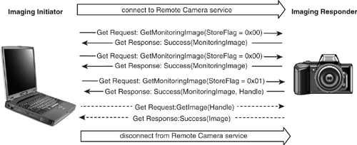
For an Imaging Responder which allows image capture, such as a digital camera: the Remote Camera feature allows the Imaging Initiator to monitoring thumbnail images from the imaging responder, and to trigger the shutter on the Imaging Responder.
It uses the same GetImage, GetImageProperties and GetLinkedThumbnail functions as other features, in addition the Remote Camera feature also has a feature specific function:
- GetMonitoringImage_This is used to retrieve a monitoring image from an Imaging Responder which is capable of capturing images. This message can include a Store Flag which can be used to indicate whether the Imaging Responder should store the image.
Figure 20–18 shows an example sequence of messages exchanged during use of the Remote Camera feature. As with all Basic Imaging functions, the messages are carried in OBEX Put and Get messages.
First the Imaging Initiator establishes a connection to the Remote Camera service. This will involve using SDP to find the services attributes and establishing all the underlying connections through the layers of the Bluetooth protocol stack shown in Figure 20–13.
The Imaging Initiator monitors images from the Imaging Responder by sending GetMonitoringImage requests in OBEX Get requests. The Imaging Responder replies with a Success Get response containing the current image.
As long as the Imaging Initiator just wishes to monitor images, it continues sending GetMonitoringImage requests with the StoreFlag parameter set to 0x00. When the user of the Imaging Initiator indicates that he or she wants to capture an image, the Imaging Initiator sends a GetMonitoringImage with the StoreFlag set to 0x01. This triggers the Imaging Responder to store the current image. The Imaging Responder then sends the Imaging Initiator a Success response with the Image it just captured and a handle which can be used to retrieve the image from store.
The example shown in Figure 20–18 is based on Annex A of the Basic Imaging Profile. It shows just one image being stored; however, the Imaging Initiator can keep the session going as long as it wants to keep triggering the Imaging Responder to store images. The Imaging Initiator can also retrieve the captured images or thumbnails of the images. Once the Imaging Initiator has finished asking the Imaging Responder to store images, it disconnects from the Remote Camera service.
Figure 20–18 Message sequence chart for Remote Camera.
20.3.6 Remote Display
The Remote Display feature is used with an imaging responder that has display capability. It allows the user to push images for display and to control the display sequence.
It uses the same GetCapabilities, GetImagesList, and PutImage functions as other features; in addition, the Remote Delay feature also has two feature specific functions:
- PutLinkedThumbnail—This is used by the Imaging Initiator to send a thumbnail version of an image to the Imaging Responder.
- RemoteDisplay—This is used to control the display of images on the Imaging Responder. It can be used to display a specific Image or to step to the next or previous image.
Figure 20–19 shows an example sequence of messages exchanged during use of the Remote Display feature. As with all Basic Imaging functions, the messages are carried in OBEX Put and Get messages.
First the Imaging Initiator establishes a connection to the Remote Display service. This will involve using SDP to find the services attributes, and establishing all the underlying connections through the layers of the Bluetooth protocol stack shown in Figure 20–13.
The Imaging Initiator optionally sends a GetCapabilities request in an OBEX Get request. The Imaging Responder replies with a Success Get response containing its ImagingCapabilities.
Figure 20–19 Message sequence chart for Remote Display.
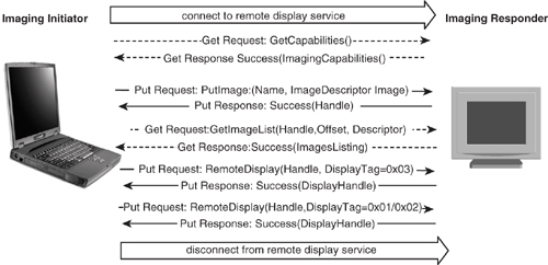
The Imaging Initiator then sends images for display to the Imaging Responder by sending PutImage requests in OBEX Get requests. The Imaging Responder stores each image and replies with a Success Get response containing a handle for the image. The image handles are used in the Remote Display message to identify images. The Remote Display message also has a DisplayTag parameter which can have one of four values:
- 0x01—NextImage: Display next image, handle parameter must be empty.
- 0x02—PreviousImage—Display previous image, handle parameter must be empty.
- 0x03—SelectImage—The handle parameter selects the image to display.
- 0x04—CurrentImage—Leave image the same, handle parameter must be empty.
The example shown in Figure 20–18 is based on Annex A of the Basic Imaging profile. It shows just one image being displayed; however, the Imaging Initiator can keep the session going as long as it wants to keep displaying images on the Imaging Responder. The Imaging Initiator can also send thumbnails for display. Once the Imaging Initiator has finished asking the Imaging responder to display images it disconnects from the Remote Display service.
20.3.7 Data Formats
Thumbnails in the Basic Imaging Profile are JPEG images 160x120 pixels. In addition, the Basic Imaging Profile supports JPEG, GIF, WBMP, and PNG formats. Proprietary encodings can be represented using a tag beginning with “USR-”. The Basic Imaging Profile makes extensive use of XML to transfer information. For example, the imaging capabilities and Image Descriptors are transferred as XML strings. Attachments are described using MIME content types. UTC time is used to identify creation and modification times.
20.4 The Basic Printing Profile
The Basic Printing Profile (BPP) defines functionality which allows devices to control a Bluetooth enabled printer and send print jobs to it without needing a dedicated driver for that printer. The profile provides plain or formatted text printing for devices with limited processing capability, XML printing which allows more complex formatting, and a reflected user interface feature which allows printer control. For networked devices, it is possible to print information from an Internet or intranet by passing a reference or pointer which identifies the item to be printed.
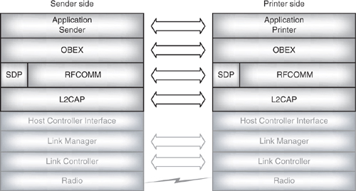
As Figure 20–1 shows, the Basic Printing Profile relies upon the Generic Object Exchange Profile and the Generic Access Profile. Figure 20–20 shows how the Basic Printing profile relies upon OBEX for data transfer. The profile follows the OBEX client/server architecture with the Sender side acting as the client device and the Printer side taking the server role.
The Printer side supports four modes:
Figure 20–20 Printing protocol stacks.
- Bluetooth off-line mode—The Printer cannot be discovered or connected with.
- Bluetooth bonding mode—The Printer is waiting to be bonded with a sender.
- Bluetooth on-line mode—Printer cannot be discovered, but can be connected with.
- Public on-line mode—Printer can be discovered and can be connected with.
In Bluetooth on-line mode only devices which already know the printer’s address will be able to send print jobs to it. In Public on-line mode any device will be able to discover the printer, so devices do not need to know its Bluetooth address in advance to send it print jobs.
All printers must support Bluetooth bonding mode and Public on-line mode; Blue-tooth off-line mode and Bluetooth on-line mode are optional.
20.4.1 Simple Push Service
The Simple Push is designed to allow devices with very limited processing capabilities to print text in a very simple way.
The Basic Printing Profile provides different OBEX channels for different services, each of which is identified by its own Universally Unique Identifier (UUID). Chapter 13 explained how the OBEX target header could be used in a connect message to specify the destination for data. For simple FilePush, the sender connects using an OBEX target header set to DPS_UUID (the UUID for Direct Printing Service).
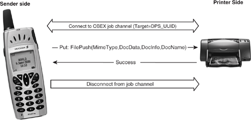
Once the sender has connected to the correct channel he or she simply sends the printer a Put request with a FilePush. The OBEX headers contain the type of the document, which is expressed as a MIME type, the document’s data, information on the document, and the document’s name.
Figure 20–21 shows a single OBEX Put operation, but if the information is too much to fit in a single Put operation, it may be split across several Put operations.
When using the Simple Push Service, the printer uses its default printer and job attributes to print the job. There are no configuration or monitoring facilities, and the job can’t be cancelled once it’s been sent to the printer.
Figure 20–21 Message sequence chart for printing a file using Simple Push.
20.4.2 Referenced Objects
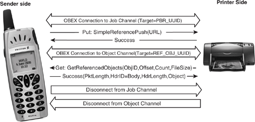
The Simple Push service also supports a method of passing references to the printer, then having the printer get the referenced object from the sender, as shown in Figure 20–22.
In order to send a reference to the printer, the sender must first connect using an OBEX target header set to PBR_UUID (the UUID for Print By Reference). The sender may then send the Printer a Put request with a SimpleReferencePush. As a minimum the OBEX headers must contain the URL of the reference. Optionally, more information can be sent. Some possibilities are information on how to locate a server which can supply the reference, type information, authentication information, a billing code, and even instructions to the printer to print the object on a new sheet of paper. Figure 20–22 shows the simplest case where just a URL is sent.
Figure 20–22 Message sequence chart for printing a reference using Simple Push.
The SimpleReferencePush is sent as an OBEX Put command using the following headers:
- Type: Simple Reference, XML Reference, or reference list.
- Body: Contains the URL of the reference.
- Description: A description of the object referenced.
- Name: Contains an Object Identifier locally identifying the reference on the Sender.
- HTTP: This can contain authentication credentials if they will be needed to retrieve the reference.
The Printer acknowledges the Push operation with a Success response, then opens a second channel back to the Sender and uses this channel to request the information from the sender. This second channel is connected using a Target Header of REF_OBJ_UUID (the UUID for the Referenced Objects Channel, also called just the object channel). On the object channel the Printer sends an OBEX Get request with a GetReferencedObjects. The OBEX headers contain an ObjectIdentifier, a byte offset, count, and filename.
Why use two channels when the sender could simply collect all information and send it down a single channel? The answer is that the sender may not have enough memory or processing power to download a complete page and transform it into a format the printer can process. By using references the Sender has shifted a lot of the memory and processing requirements onto the printer. As printers are likely to have comparatively large memory and processing reserves, it makes sense that they should do the processing and formatting.
The reference is retrieved using a GetReferencedObjects operation. This is an OBEX Get containing the following parameters:
- ObjectIdentifier—Identifies the referenced object on the Sender.
- Offset—Used when several requests are needed to retrieve a whole object. The offset gives how many bytes into the object retrieval should start.
- Count—Says how may bytes should be sent.
- FileSize—This is ignored in the request, but its presence causes the sender to return the size of the requested object in the response.
The ObjectIdentifier is sent in a Name header. The Offset, Count, and FileSize are all packed into an Application Parameters header.
When the Job channel is disconnected by the sender, the printer disconnects from the Object channel. Because the Object channel closes when the Job channel closes, the sender should allow any referenced objects to be retrieved before closing the Job channel.
20.4.3 Job Based Service
This service can be used to print more complex documents. As with the simple push service, the job based service can be used with referenced objects, or plain documents. The difference is that with the job based service the sender initiates a print session, rather than just using a single push operation. The session allows the sender to use a series of commands to configure and control the printer.
- CreateJob Create—Used to submit job attributes, in return the sender gets a JobID.
- SendDocument—Transfers print content to the printer; used with CreateJob.
- GetJobAttributes—Used to query attributes and status of a job.
- GetPrinterAttributes—Ask for the status and capabilities of the printer.
- CancelJob—Used to cancel a job using the JobID.
- GetReferencedObjects—Used to retrieve referenced objects from a sending device.
- GetEvent—Used to ask for status information during printing.
- CreatePreciseJob—Used for enhanced layout.
- GetMargins—Used for enhanced layout.
- SendReference—Sends a reference for printing.
- GetRUI—Gets a web page which gives a user interface to configure and control the printer.
Figure 20–23 shows a simple example of a print session. First a CreateJob is sent in an OBEX Get message. The CreateJob can be used to specify how the printer should be configured for this job. The example shows JobName and Copies attributes being sent with the CreateJob. These are just two of the possible attributes which can be sent with a CreateJob. The following attributes could be sent:
Figure 20–23 Message sequence chart for a simple print job.

- JobName—A user friendly name.
- JobOriginatingUserName—Name of user who sent the job.
- DocumentFormat—The MIME type of the document.
- Copies—Number of copies of the document to print.
- Sides—Single sided, double sided flip on long edge, double sided flip on short edge.
- NumberUp—Number of document pages to print on a single side, options are one per side, two per side or four per side.
- OrientationRequested—Portrait, landscape, reverse-landscape, reverse-portrait.
- MediaSize—Size of paper to print on.
- PrintQuality—Draft, normal, or high.
- MediaType—Type of paper, acetate, etc. to print on.
- CancelOnLostLink—Whether to cancel printing if the Bluetooth link is lost.
These attributes are sent as a Simple Object Access Protocol (SOAP) message. The SOAP message is carried in the body of the OBEX Get message. SOAP is an XML language, so all the attributes are laid out in plain text one attribute per line surrounded by markers explaining what the attribute is. So, for instance, if the JobName was “MyPrintout”, the SOAP encoded attribute would be:
<JobName>MyPrintout</JobName>
The Printer must be able to handle all these attributes. That doesn’t mean it has to support every single value: for instance, it may only print single sided, but it must understand and react properly to a request for double sided printing.
The Sender does not have to support any of the CreateJob attributes, if any are missed out a default value is used.
The CreateJob Response has just two attributes:
- JobName—A user friendly name.
- JobID—The identifying number the printer has allocated for this job
- • OperationStatus—The Status of the job, indicating whether the CreateJob succeeded or failed, if it failed the reason is given with an error code.
Once the job has successfully been created, the document can be sent. Figure 20–23 shows a document being sent with a SendDocument operation carried in an OBEX Put request. The attributes of the SendDocument are the document type, the content of the document itself, and the JobID. PrintByReference can also be used to send content for printing, in the same way as it can be used to send content in the Simple Push Service.
The message exchange could stop at this point, the example shows how more messages can be used to monitor the job, and cancel it.
Figure 20–23 shows a second status channel being opened to monitor and control the job. Having a second channel means that status can be read and commands sent whilst the Job Channel is busy with the document being sent.
The figure shows a GetJobAttributes being sent, a JobID identifies the Job, and a list of attributes is sent so that the printer knows what to report on. The printer replies with the JobID and all of the requested attributes. Possible attributes are:
- JobState—Printing, waiting, stopped, completed, aborted, cancelled, unknown.
- JobName—The user friendly name allocated when the job was created.
- JobMediaSheetsCompleted—Some printers don’t count and will always report zero!
- NumberOfInterveningJobs—Place in print queue.
- OperationStatus—Whether the GetJobAtributes operation succeeded.
In our simple example the user successfully gets the response back then decides he or she doesn’t want the job after all—perhaps the NumberOfInterveningJobs attribute was quite large and the user doesn’t want to wait. The user cancels the job with a CancelJob operation on the Status channel and gets a Success response back with a JobID and status confirming that the Job has been cancelled.
Having cancelled the job, the Sender can disconnect the Job and Status channels.
In Figure 20–23 the job was monitored using a GetJobAttributes. A GetEvent operation can also be sent on the status channel to monitor the job. The GetEvent response always contains the same set of attributes:
- JobID—The ID allocated when the job was created.
- JobState—The user friendly name allocated when the job was created.
- PrinterState—Idle, processing or stopped.
- PrinterStateReasons—Error code to explain PrinterState if it is stopped.
- OperationStatus—Whether the GetEvent operation succeeded.
To further monitor the state of the printer, a GetPrinterAttributes operation can used. This is sent in an OBEX Get request on the status channel. The GetPrinterAttributes operation can request the following attributes:
- PrinterName—The user friendly name of the printer.
- PrinterLocation—A string such as “My Office”.
- PrinterState—Idle, processing or stopped.
- PrinterStateReasons—Error code to explain PrinterState if it is stopped.
- DocumentFormatsSupported—An array giving MIME Types of supported formats.
- ColorSupported—Whether printer supports full colour.
- MaxCopiesSupported—Maximum value for Copies parameter in CreateJob.
- SidesSupported—Whether printer supports double sided printing.
- NumberUpSupported—Maximum NumberUp value for NumberUp in CreateJob.
- OrientationRequestedSupported—Whether the printer can print at different orientations.
- MediaSizesSupported—Sizes the supported, these may not be loaded at present.
- MediaTypesSupported—Types of media supported—these may not be loaded at present.
- MediaLoaded—Details, size and type of media loaded, this is an array allowing details of more than one medium to be passed.
- PrintQualitySupported—Possible values for PrintQuality parameter in CreateJob.
- QueuedJobCount—Number of jobs in the printer queue.
- ImageFormatsSupported—The types of image the printer can interpret in an XML document.
- BasicTextPageWidth—Number of characters in a line for default font and paper size.
- BasicTextPageHeight—Number of lines in a page for default font and paper size.
- PrinterGeneralCurrentOperator—Contact information for printer support.
- OperationStatus—Whether the GetEvent operation succeeded.
The GetPrinterAttributes can be sent before CreateJob, as it contains useful information on the printer’s capabilities which can be used to decide the parameters for the CreateJob operation.
20.4.4 Enhanced Layout—Formatting Print Jobs
When using the Job Based service the CreatePreciseJob and GetMargins operations can be used to control formatting.
CreatePreciseJob has the same attributes as CreateJob, except that if the printer cannot print the job precisely as the attributes specify, then the document is not printed. If the printer knows in advance that it cannot print as requested, it will return an error immediately and refuse the job. If it discovers during the job that it cannot print (for example, because it cannot retrieve a referenced object), then it will abort the job.
GetMargins is used to find out about margins needed for a particular size and type of medium. The GetMargins request specifies the size and type, the response gives values for Top, Right, Bottom, and Left Margins and an OperationStatus.
The GetMargins request is sent before the CreateJob to find out how the job should be formatted or to help choose an appropriate medium type and size.
20.4.5 Reflected User Interface Service
The previous sections showed how a printer can be controlled using various standard operations. The ReflectedUserInterface can be used to provide a richer user interface which can control the printer in ways not specified above.
The GetRUI operation gets a web page which gives a user interface to configure and control the printer. By following hyperlinks on the page the user can invoke operations particular to that printer.
The sender sends GetRUI in an Obex command, the printer responds with the user interface which is sent as an XML form. At the sender side this form is presented to the user for data entry. The sender then returns form information along with a Job Identifier in another Get OBEX command. The printer may return another form in the response; for example, it could return a status page.
Many control forms may be sent between sender and printer to fully configure and monitor a print job.
20.5 The Hard Copy Cable Replacement Profile
The Hard Copy Cable Replacement Profile (HCCP) provides a way of printing using a printer driver on the client device. The profile supports a 1284ID string which can be used to identify a driver. It also provides simple credit based flow control. The profile copes with loss of connection in the middle of a print job. The profile also allows a client to register an interest in certain events—this will cause the server to send an asynchronous notification if the event happens during a job.
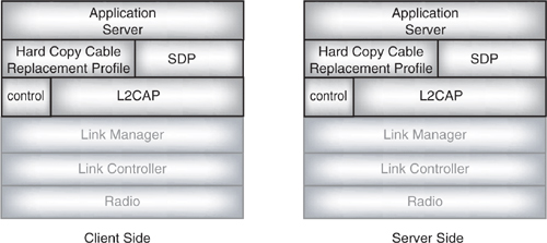
Figure 20–24 shows how simple the protocol stack for the hard copy cable replacement profile is. The profile rests directly on L2CAP; there is no need for RFCOMM or OBEX layers. The client side has an application running on the HCRP layer which is usually a printer driver. On the server (printer) side the application is likely to be an interpreter or some other application which can generate a page description format.
Figure 20–24 Protocol stacks for Hard Copy Cable Replacement Profile.
The Hard Copy Cable Replacement Profile relies upon having the correct driver for a printer installed, so it provides a command to identify the driver.
The Hardcopy Cable Replacement Profile makes use of three channels:
- Data—Used to transmit device-specific data including the document to be printed and any control which is specific to the printer driver.
- Control—Used to transmit HCRP control requests.
- Notification—Used by the server to notify the client of asynchronous events. Each event has a different channel, and the notification channel numbers can be obtained via SDP.
The control channel is used to identify the printer driver type, get status information, handle flow control, request notifications, and also handle resets. A separate control channel is provided so that all of the control functions can be used whilst document data is being exchanged. Obviously, if you want to reset a printer because a job is stopped, you don’t want to have to wait for the job to finish exchanging data before you can request a reset!
Messages are sent as PDUs in L2CAP, the PDU structure is shown in Figure 20–25. Each message begins with a PDU ID, a Transaction ID, and a Parameter length. The PDU ID identifies the type of message, and the transaction ID is a number used to match requests and replies together. Every time a request is sent, the transaction ID is incremented by one, and replies copy the transaction ID from the request they are responding to. The parameter length simply gives the number of bytes of parameters following.
Figure 20–25 PDU structure for Hard Copy Cable Replacement Profile.
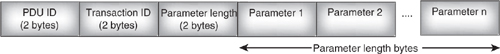
A reply PDU always has a 2 byte status code as its first parameter. This status is used to tell whether the request succeeded or failed. It can also indicate reasons for failure.
20.5.2 Control
The control channel is used for sending control specific to the Hard Copy Cable Replacement Profile. Control messages which are generated by the printer device driver are sent on the data channel, (see section 20.5.3).
One of the most important control messages is the CR_Get1284ID, which is used to identify the correct driver for a printer. This is sent by the client to the server, and the server returns a CR_Get1284ID reply which can be used to identify a suitable driver for the printer.
Another useful command is CR_GetLPTStatus which can be used to check on the printer’s status including whether it has run out of paper. This command is in addition to any commands provided by the device driver. The printer sends a CR_GetLPTStatus reply with a byte of status bits.
20.5.1 Notifications
The notification channels carry notifications of asynchronous events from the printer to the client. Figure 20–26 shows an example of messages used in the notification process.
Figure 20–26 Message sequence chart for notifications.
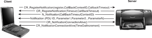
Before it can receive notifications, the client has to register an interest with the server. This is done by sending the CR_RegisterNotification command on the Control channel. This command has three parameters:
- register—Whether to register or deregister for notification.
- CallbackContextID_An ID which will be sent back with the notification.
- CallBackTimeout—The time to keep a notification channel alive after sending a request. This is just a request, and the server can choose to shut down a notification channel sooner than the requested timeout.
The server replies with a CR_RegisterNotification reply giving a timeout, which is the time before the notification request will expire, and a CallBackTimeout, which gives the time the server will shut down the notification channel after sending a notification.
When the client has registered for notifications, and an event occurs on the server, the server sends a N_Notification on the appropriate notification channel. This tells the client that the server has notification information to deliver. The N_Notification carries the CallbackContextID which has been registered.
How the client reacts to the N_Notification will vary between implementations. The client may have to open a return channel so that it can respond to the notification, or it may just wait to receive more information.
The server then sends a notification PDU which contains a PDU ID identifying the event which has occurred. It may also contain a set of parameters giving more information.
It is assumed that the client has finished processing the notification when the notification channel closes. If the client needs more processing time, it can send a CR_NotificationConnectionAlive request on the control channel to keep the channel open for longer—this request has no parameters. The server adds a value TimeOutIncrement to the CallBackTimeout to keep the notification channel open a little longer and tells the client what the TimeOutIncrement is by sending it back as a parameter in a CR_Notification-ConnectionAliveResponse.
There are two commands used to reset a printer: CR_SoftReset and CR_HardReset. If CR_SoftReset is used, the printer remembers whether notifications are registered. If CR_HardReset is used, it will forget all settings and CR_RegisterNotification must be sent again if the client requires notifications.
20.5.3 Flow Control
The Hard Copy Cable Replacement Profile uses a credit based flow control scheme similar to the system used by the version 1.1 of RFCOMM. Each side requests credit from the other and keeps a count of the number of bytes of credit granted. As data is sent the count reduces by the number of bytes sent.
The PDUs used for credit based flow control are:
- CR_DataChannelCreditGrant—Used by the client to grant credit for the data channel to the server.
- CR_DataChannelCreditRequest—Used by the client to request an increase in credit granted to it by the server.
- CR_DataChannelCreditReturn—Used by the client to return credit it will not use. This might be used at the end of a print job.
- CR_DataChannelCreditQuery—Used by the client to tell the server how much credit it has left on the data channel to the server. The server replies with how much credit is has left on the data channel to the client.
Clients should periodically grant credit to the server to ensure that data continues to flow. This is particularly important as the server has no message to request credit from the client.
20.5.4 Data Format
The format for sending data on the data channel is not specified; it will depend upon the printer driver being used. This means that the data channel can be used for sending driver-specific commands as well as the document data itself.
Effectively, the data channel carries the same information that would be sent on the cable the Bluetooth link is replacing.
20.6 Summary
This chapter has examined five draft profiles all of which have reached version 0.9 and are available to adopter members of the Bluetooth SIG to download from the SIG Web site http://www.Bluetooth.org/member/specifications.htm.
The Human Interface Profile can be used to control mice, keyboards, and other human interface devices such as joysticks. It has two modes: the boot mode, simple enough to be implemented in a BIOS, allows a keyboard or mouse to be used before an operating system has booted. The report mode is more complex and allows for richer interaction including force feedback effects. The Human Interface Device Profile reuses protocols and data structures from USB human interface devices.
The Hands-Free profile extends on the capabilities of the Headset Profile. The Hands-Free profile allows a hands-free user to control a phone dialing, receiving calling line IDs, and even optionally using voice recognition via a remote user interface. The Hands-Free profile uses AT commands as did the Headset Profile, but the Hands-Free profile defines an extension to the AT command set specifically for Bluetooth devices.
The Basic Imaging profile allows transfer of images, thumbnails, and linked attachments between devices. In addition to transfer of individual images, images can be browsed, an archive feature allows groups of images to be backed up, a remote camera feature allows control of a camera, and a display feature allows groups of images to be viewed on a remote display.
Basic Printing is used to transfer plain text or XML formatted documents to a printer without using a dedicated printer driver. The profile provides a means for a printer to retrieve content via references embedded in a document. To enable more complex functionality the printer can send a reflected user interface. This uses XML forms sent to the user to provide a user interface which can be customised by each printer.
The Hard Copy Cable Replacement Profile allows printing using a dedicated printer driver. A data channel is used to simulate the printer cable and carries raw implementation specific data. A control channel provides profile defined control signals including credit based flow control facilities, and notification features allow the printer to inform the sender of events related to printing.
At the time of writing these new profiles are released to all adopters, but have not yet reached version 1.0. However, they have all reached version 0.9 and changes between 0.9 and 1.0 are usually minor.